A signal generator is an important feature that generates specific measurement signals. These signals can be sent to the device or system for evaluation.
To conduct audio measurements, it is essential to have specific measurement signals that can be produced using a built-in signal generator. You can generate a signal using the “Generator” button in the ribbon bar.
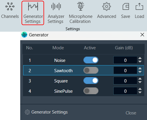
By utilizing the “On/Off” function, you can activate or deactivate a signal. It is possible to generate multiple signals using this feature. The number of signals visible in the “Generator” window is determined by the number of instances specified in the Generator settings.
The gain of the generator signal can be adjusted in 1 dB steps with the Gain control.
To configure the signal, click on the “Generator Settings” to open the advanced RTA setting dialogue box. Here you can configure different generator modes.
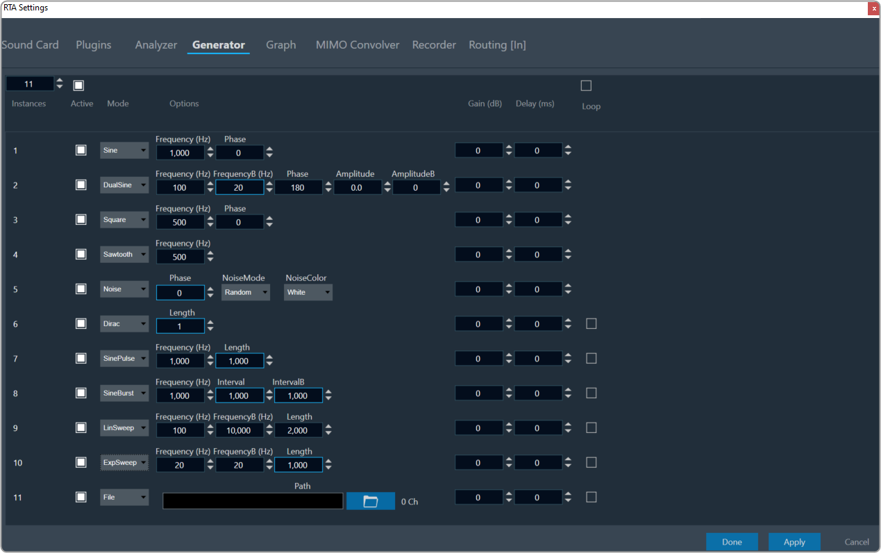
On the RTA setting dialogue box, enter the instance value or use the increase and decrease buttons to change the instance value.
Using the “Mode” option, you can select different signals from the drop-down list. The available modes are listed below.
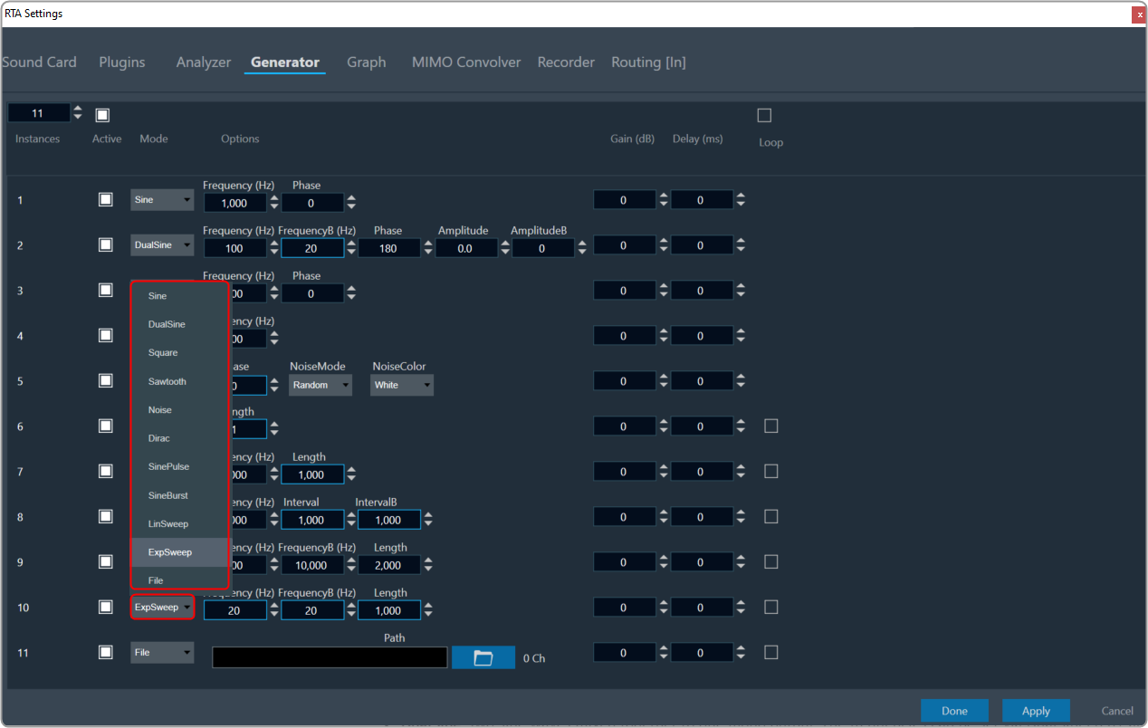
- Sine: A single sine wave adjustable in the audible range between 20 Hz and 20 kHz by SineFreq. The phase between the two output channels can be set by SinePhase.
- DualSine: Two sine waves mixed together to one mono output. The frequencies can be set via DualSineFreq1 and DualSineFreq2, the mixing gains by DualSineGain1 and DualSineGain2.
- Square: Similar to the standard sine wave but shaped as a square wave.
- Noise: This is a stereo noise generator mode. In the Random mode, a regular noise signal is produced. However, when the Noise Mode is set to Pseudo, a multi-sine signal is generated where a sine wave is produced on each frequency bin of the chosen analyzer FFT. The phases of all the sine waves are distributed randomly to create a signal similar to noise.
This mode is used for spectrum analysis of static transfer functions, and it is essential to set the analyzer window function to Rectangle for optimal results, producing very smooth spectrums.
The NoiseColor can be changed between Pink (-3 dB per octave fall off) and White (flat frequency spectrum).
By adjusting the phase the output can be coded in a way so that surround upmixers can pan the signal according to the adjusted angle. The output changes from mono at 0° to L/R uncorrelated at 90° to out of phase at +/- 180°. - Dirac (Dirac Pulse): In this mode one sample wide pulses are generated. The time between two pulses is set by SignalLength.
- SinePulse: This mode generates sine squared pulses. The shape of the pulse is set by SinePulseFreq, the interval between two pulses by SinePulseInterval.
- SineBurst: In this mode sine bursts are generated. The frequency is set by SineBurstFreq, the length of the burst by SineBurstLength, and the interval by SineBurstInterval.
- LinSweep: This generates a sine sweep starting from SweepStartFreq and ending at SweepEndFreq. The length of the sweep is set via SweepLength. The frequency progress is linear.
- ExpSweep: Similar to LinSweep only with an exponential frequency progress.
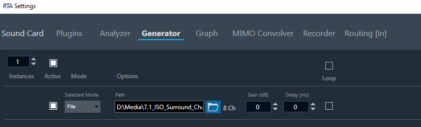
- File: Click on the folder and select the wav file. Based on their selection, the number of channels present in the WAV file will be displayed here. For the selected file, each channel of the selected file will be used as the generator input.
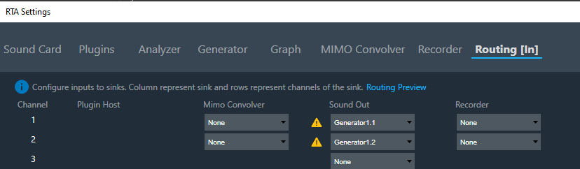
After selecting this mode the user has to adjust the routing settings, hence number of channels depends on the selected file.
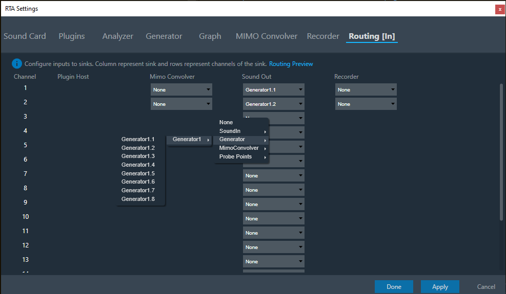
After changing the mode from file mode to any other mode, this routing adjustment has to be adjusted according to the user need and will be signaled by GTT as shown below.
Use the “Active” checkbox to either select or deselect all traces. When you select the checkbox at the top, all instances in the window will be automatically selected. Similarly, when the top checkbox is deselected, it will unselect all the traces in the trace window.
Additional Configurations
Loop: If you enable the “Loop” option while using Dirac, SinePulse, SineBurst, LinSweep, ExpSweep, or File mode, the generator will play the chosen signal repeatedly when the Play button is pressed. However, if the loop option is disabled, the generator will play time-limited signals upon pressing the “Play” button.
Delay: You can enter the Delay value. The delay represents the time interval between the input and output of the generator, indicating the time it takes for the generated signal to propagate through the system.
Gain: You can enter the Gain value. The Gain setting allows you to increase or decrease the volume or strength of the generated signal.
The signal generator has a stereo output. This is relevant for signals with adjustable inter-channel phase or stereo wav file playback.