Control GroupSplitter

The Control GroupSplitter audio object splits one control group input into multiple individual control outputs.

Use Case: This object can be deployed if user wants to split the block control to individual control signals which needs to be connected to different audio objects.  

Control GrouperSplitter Properties

Below table describes about the Control GroupSplitter audio object properties and functionality.

Properties Description
# of controls in Group Enter the number of control outputs. It is also the number of signals within the one group to control input.

The number of control group input is always 1.

  • Range: 2 to 128
  • Data type: xFloat32
  • The default value is set to 2.

The Control GroupSplitter audio object accepts a single block control at its input and splits it into a user-configurable number of single control outputs.

Display Name Display name of the Control GrouperSplitter audio object in signal flow design. It can be changed based on the intended usage of the object.

Mode

There are no mode available for Control GroupSplitter audio object.

Additional parameters

There are no additional parameters available for Control GroupSplitter audio object.

Tuning Parameters

There are no tuning parameters available for Control GroupSplitter audio object.

Control Interface

The object always has N single control outputs. The number N is described via the number of elements variable in SFD. The object always has one group control input.

Native Panel

Control GroupSplitter audio object does not support native panel.

Control Math

The Control Math audio object provides the ability to manipulate input control signals.

Control Math Properties

Below table describes the Control Math audio object properties and functionality.

Properties Description
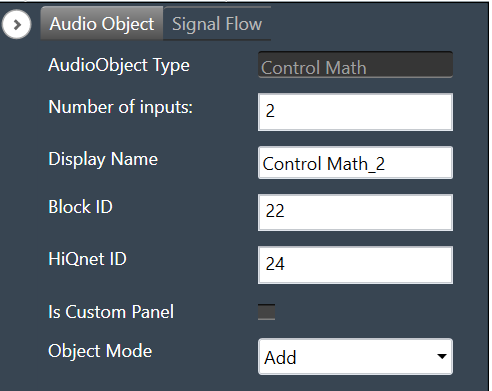
Number of outputs/inputs Enter the number of control outputs or inputs.

  • When the object mode is set to ADD/SUBTRACT/MULTIPLY/MAXIMUM/MINIMUM/EQUAL/ AND/OR/NOR /NAND /XOR the input control pin is enabled.
    • Input value ranges from 2 to 16.
    • The output value is 1.
    • The default value is set to 2.
  • When the object mode is set to LIN2DB / DB2LIN /INVERT / RECIPROCAL / SQUARE / SQUAREROOT the input control pin is equal to the output control pin.
  • When the object mode is set to DIVIDE/GREATER/LESS, the input control pins are 2 and the output control pin is 1.
  • When the object mode is set to NOT/CTRLDELAY, the input and output control pin is 1.
  • When the object mode is set to CTRLSPLIT, the input control pin is 1, and output control pins are configurable between 2 to 32.
  • When the object mode is set to CTRLDUPLICATE, the input control pins are configurable between  1 to 16 and the output control pins are twice the input control pins.
  • When the object mode is set to NONLINEARCLIP, the input control pins are 3, and the output control pin is 1.
  • When the object mode is set to INDEX, the input control pins are configurable between  2 to 255, and the output control pins are 2.
Display Name Display the name of the control math audio object in signal flow design. It can be changed based on the intended usage of the object.
Object Mode Control Math audio object supports twenty-six modes of operation. This audio object can be configured in the SFD to operate in one of the following modes:

  • Add
  • Subtract
  • Divide
  • Multiply
  • Minimum
  • Maximum
  • Lin2dB
  • dB2Lin
  • Invert
  • Square
  • Reciprocal
  • SquareRoot
  • And
  • Or
  • Xor
  • Not
  • Nand
  • Nor
  • Greater
  • Less
  • CtrlSplit
  • CtrlDuplicate
  • CtrlDelay
  • NonLinearClip
  • Equal
  • Index

The default object mode is set to Add.

Mode

The Control Math audio object supports the following modes.

Mode Description
ADD In this mode, control inputs into the object are summed up and their sum is fed to the output of the object.
SUBTRACT The difference between the first control input and the summation of the remaining control inputs into this object is sent out at the output.
MULTIPLY Takes in input controls and writes their product to the output of the object.
DIVIDE Takes 2 input controls and writes the result of their division to the output. If the divisor is zero, the result is set to the maximum float value.
MAXIMUM Takes the input controls and writes out the maximum of the values.
MINIMUM Takes in input controls and writes out the minimum of the values.
LIN2DB Takes a linear control value as an input and outputs its logarithmic equivalent to the specific output pin. If the input is less than or equal to zero, the result is set to zero.
DB2LIN Takes a logarithmic control value as an input and outputs its linear equivalent to the specific output pin.
INVERT Reads in a control value and outputs the negative (inverse) of that value to the specific output pin.
RECIPROCAL Takes in a value, x, and outputs its reciprocal (1/x). If the input value is zero, the result is set to the maximum float value to the specific output pin.
SQUARE Takes in a value, x, and outputs its squared value to the specific output pin.
SQUAREROOT Takes in an input value, x, and outputs its square root. If the input is negative, the result is set to zero to the specific output pin.
AND Takes in multiple inputs and outputs the logical AND operation of these inputs.
OR Takes in multiple inputs and outputs the logical OR operation of these inputs.
XOR Takes in multiple inputs (x1, x2, x3, xn) and outputs the logical XOR operation (((x1 xor x2) xor x3) xor xn) of these inputs.
NOT Takes in an input, and outputs the NOT
NAND Takes in multiple inputs (x1, x2, x3, xn) and outputs the logical NAND operation (((x1 nand x2) nand x3) nand xn) of these inputs.
NOR Takes in multiple inputs (x1, x2, x3, xn) and outputs the logical NOR operation (((x1 nor x2) nor x3) nor xn) of these inputs.
GREATER Takes in 2 inputs, and and outputs true if.
LESS Takes in 2 inputs, and and outputs true if.
EQUAL Takes in multiple inputs and outputs true if all the input values are equal.
SPLITTER Takes in an input control and writes the output to a user-specified number of output pins.
DUPLICATE Takes in a user-specified number of inputs and writes each input out to 2 output pins.
DELAY Takes in a user setting delay (in ms) and writes out the output only after that delay time has passed.
NONLINEARCLIP Takes in 3 inputs, x, min, and max.

  • Provide the output as max if x is greater than max.
  • Provide the output as min if x is less than min.
  • Provide the output as x if x is greater than min and less than max.
INDEX It takes in multiple control inputs and outputs two control values.

  • The first control output returns the index of the minimum value among the control inputs.
  • The second control output returns the index of the maximum value among the control inputs.

In case of maximum or minimum values being the same, it returns the index of the first encounter.

Additional Parameters

The Control Math audio object supports additional configuration which allows to enable or disable Block Control. Which can be enabled or disabled by selecting between Block Control Disabled and Block Control Enabled. The object shall support Block Control in the following operating modes:

Block Control Enabled –

  • Set “Object Mode” to EQUAL / AND / OR / NOR / NAND / XOR to enable the Block control, the number of input control pins can be grouped to one input block control pin.
  • Set “Object Mode” to LIN2DB / DB2LIN /INVERT / RECIPROCAL / SQUARE / SQUAREROOT to enable the Block control, the number of input and output control pins can be grouped to one input block control pin and one output block control pin respectively.

By default, the Block Control function is disabled.

Tuning Parameters

There are no tuning parameters available for the Control Math audio object.

Control Interface

There are no control parameters available for the Control Math audio object.

Native Panel

Control Math audio object does not support the native panel.

Control Grouper

The Control Grouper audio object allows to merge two or more individual controls and combining them into a single output group, and then send as one signal output group to the connected object.

Use Case: The Control Grouper audio object is useful in context of the Block Control feature. When control signals are received from controlIn AO it will be received as individual control signals. If audio object needs all control signals together then control grouper can be used to combine the control signals. 

Refer block control documentation for more details. 

Control Grouper Properties

Below table describes about the Control Grouper audio object properties and functionality.

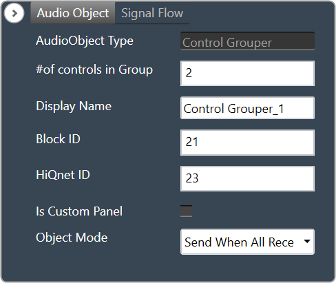
A screenshot of a computer Description automatically generated with medium confidence

Properties Description
# of controls in Group Enter the number of control inputs. It is also the number of signals within the one group to control output.

The number of control group output is always 1.

  • Range: 2 to 128
  • Data type: Float
  • The default value is set to 2.
Display Name Display name of the Control Grouper audio object in signal flow design. It can be changed based on the intended usage of the object.
Object Mode The audio object supports two modes of operations.

  • Send When All Received (Default mode)
  • Send On Apply

Mode

Control Grouper supports two modes.

  • Send When All Received (Default mode)
  • Send On Apply

A screenshot of a computer Description automatically generated

Mode Description
Send When All Received In this mode Control Grouper AO does not send a control group output every time a control input is received. The Control Grouper AO waits till all the control inputs are received and then sends the control group output.

If the control inputs are coming at a different rate, the object sends the control group output at the rate of the slowest incoming control input.

Send On Apply In this mode, Control Grouper AO has an additional “Apply” input pin. When input is received on apply pin, Control Grouper AO sends the group output.

Control inputs have default values. These values are exposed as tuning parameters, these values can be modified using state variable explorer. These values are used, when one or more inputs are not received before the input on apply pin is received.

Additional Parameters

There are no additional parameters available for Control Grouper audio object.

Tuning Parameters

There are no tuning parameters available for Control Grouper audio object.

Control Interface

There are no control parameters available for Control Grouper audio object.

Native Panel

Control Grouper audio object does not support the native panel.

Control Multi Adder

The Control MultiAdder audio object provides the ability to manipulate input control signals. Refer description column of num elements for algorithm description. 

Use Case: This object can be deployed whenever the addition of control inputs is required. Additionally, this object is used as the LUT Adder in Halosonic.

ControlMultiAdder Properties

Below table describes about the Control MultiAdder audio object audio object properties and functionality.

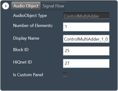
A screenshot of a computer Description automatically generated

Properties Description
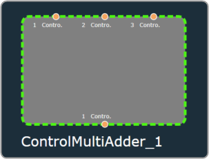
Number of Elements A minimum of three control inputs into the object are summed up and their sum is fed to the control output of the object. Each time the Control Multi Adder control input is set, it calls the corresponding control output. The object has 3 control inputs for elemental addition and forwards control value into an output.

A screenshot of a computer program Description automatically generated

Example: If the numElements is 4, there will be 4 control outputs [y1, y2, y3 and y4] and 12 control inputs [x1 to x12]. The control outputs are computed as shown in the figure below.

Maximum control inputs possible for a control multi adder instance are 255.

For N elements specified from the configuration, 3N control input values would give N control output values. The number of control outputs is selected by numElements.

The number of control inputs = 3 * numElements.

The maximum number of control outputs is limited to 85, So the maximum number of control inputs is 85*3 = 255.

Display Name Display name of the Control MultiAdder audio object in signal flow design. It can be changed based on the intended usage of the object.

Mode

There are no mode available for Control MultiAdder audio object.

Additional parameters

There are no additional parameters available for Control MultiAdder audio object.

Tuning Parameters

There are no tuning parameters available for Control MultiAdder audio object.

Control Interface

There are no control parameters available for Control MultiAdder audio object.

Native Panel

Control MultiAdder audio object does not support native panel.

Limiter User Guide Supplement

The Limiter object can be used to create a hard-stop peak limit on an input signal.  Because it operates on a feedback basis only, there is the possibility for the input signal to overshoot the limit set by the user for a short duration while the algorithm pulls down the signal gain.

The basic trade-off of any feedback limiter is strict regulation to the threshold versus distortion. The more aggressively the limiter is working to pull down (attack) the signal level to the threshold, the more distortion will be produced. Distortion, fluttering and/or pumping can also be produced when the signal level is released from regulation, if the resulting gain lift happens too fast.

Limiter Operation Description

  • Attack Phase – When the Limiter detects that the Threshold value has been exceeded, it reduces the gain at a rate set by a combination of the Attack parameter and how much the input signal exceeds the Threshold value. The gain is reduced until the signal level is at or below the Threshold value. The faster the gain is reduced, the more distortion will be created. There is a minimum attack time time period during which the algorithm is determining signal level.
  • Hold Phase – After the signal drops below the Threshold value, the Limiter will hold the gain steady for a time determined by the Hold parameter. It stops the gain reduction phase and begins to hold. Then at the point when the signal has fallen below the Hold threshold value, the Release phase begins.
  • Release Phase – The gain is raised back to the starting gain, set by the Gain parameter, at a rate determined by the Release parameter. The faster the gain is raised, the more distortion will be created.

Limiter Tuning Parameters In-Depth Description

  • Gain – this is a gain stage before the limiting portion of the algorithm, which sets the starting gain. This gain is applicable before limiting starts, after limiting is fully released and while no limiting is occurring. Gain changes during limiting will be added to this value.
  • Threshold – this is the peak level under which the Limiter will attempt to keep the signal. Overshoot can happen during the Attack phase, both while the algorithm is computing signal level and while reducing gain to meet the Threshold value.
  • Hold Threshold – this is the signal level, relative to the Threshold value, under which the Release phase will begin. This small offset keeps the algorithm from changing phases too quickly and provides an extra guard against exceeding the Threshold value, helping to reduce fluttering and distortion.
  • Attack Time – this is how fast, and thus how aggressively, the Limiter will pull down the signal to meet the threshold. If strict adherence to the Threshold parameter is desired, then Attack should be set very low. This will produce more distortion than a more relaxed Attack value, but if the input signal is not anticipated to exceed the Threshold by very much, then the distortion will be relatively low. Worst case is when the Attack is set low and the input signal level is high compared to the Threshold value. There is a minimum attack time the user can set, which corresponds to the time period during which the algorithm is determining signal level.
  • Hold Time – this sets the time during which the Limiter will hold the gain value steady. Having a non-zero value here can smooth the Limiter operation so that fluttering and pumping are less audible.
  • Release Time – this sets the time during which the Limiter will begin raising the gain back to the original value. Extremely short release times cause very fast gain changes which can lead to fluttering, pumping and distortion.

SFD-Core Objects Toolbox

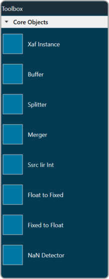
The Toolbox contains the core objects that were retrieved from the xAF dll. The objects that can be used within the core to create the device signal flow are called core objects. Each core object has its own purpose and solves parametric issues which block routing within the core.

Core Objects are classes that are part of the Audio Core (virtual core) class and operate at a higher level than audio objects. The audio processing class itself is a core object. The relationship between core objects and Audio core is similar to that of audio objects and the Audio Processing class.
Graphical user interface Description automatically generated

The execution order (or index) of the core object is displayed by Core Object Id. Routing determines the order in which core objects are executed within a core. The core objects that are connected to the core input will be executed first, and the core objects that are connected to the root object after that will be given the next execution order.

The device identification feature is enabled for audio libraries version 13 and higher.

Xaf Instance

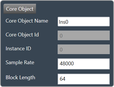
The Xaf Instance is the core object inside which the signal flow for that instance can be created.
Graphical user interface, text Description automatically generated

  • Core Object Id (execution order of core-object with-in core) and Instance Id (index of xAF instance with-in core, based on execution order) will be displayed as read-only fields.
  • The sample rate and block length of the instance will control signal flow within the instance. You can change the sample rate and block length of the instance in the properties section.
    Graphical user interface, application Description automatically generated

Further information on signal flow creation is available in the GTT Signal Flow Designer guide.

Buffer

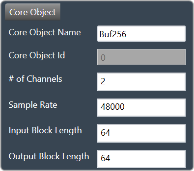
Buffer core object is used to convert the input block length into the required output block length. The buffer core object has an equal number of input and output channels. It can be used as a pass through core object OR it can be used to, as its name suggests, buffer samples from the input to the output. The object does not change the sample rate (it is the same at the input and the output).
Text Description automatically generated with low confidence

If you want to connect two core objects with different block lengths, you can use a buffer core object. As a result, the input block length will be the Block Length of the first core object, and the output block length should be the Block Length of the other core object.
Graphical user interface, application Description automatically generated

It can be configured as follows:

  • If the input block length is equal to the output block length, then it behaves as a pass through object (so you could have an audio core with a buffer object to connect the core input to the output)
  • Input and output block lengths must be integer multiple of each other
  • When input and output block lengths are not equal, the object handles taking in input at a lower block length and outputting it at a higher one and vice versa. For example, it facilitates the connection of an object at block length 32 to an object at block length 64

Introducing this object into your signal flow for any case but pass through WILL result in latency at the output.

Splitter

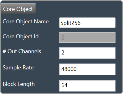
Splitter core object is used to convert one input to multiple outputs of the same sample rate and block length.
Text Description automatically generated

  • This core object always has a single input.
  • In order to make routing from any core object to the splitter both the source core object and splitter core objects sample rate and block length should match.
  • Number of output channels for the splitter is configurable.
    Graphical user interface, text, application Description automatically generated

It is not to be confused with the Splitter audio object.

This object operates in parallel to an xAF instance NOT within it.

Merger

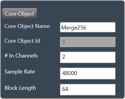
Merger core object is used to merge multiple inputs into a single output of the same block length and sample rate.
Text Description automatically generated

  • This core object always has a single output.
  • In order to make routing from any core object to merger both the source core object and merger core objects sample rate and block length should match.
  • Number of input channels for the merger is configurable.
    Graphical user interface, application Description automatically generated

It is not to be confused with the Merger audio object.

This object operates in parallel to an xAF instance NOT within it.

Ssrc lir Int

Synchronous Sample Rate Converter (SSRCs) is used to convert the input sample rate to the required output sample rate.
SSRCs are core objects that can operate within an audio core. Currently there is one implementation of SRCs in Awx.
Text Description automatically generated

Two options are provided to convert the sample rate. Both these options are mutually exclusive.
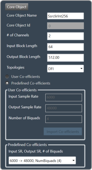
Graphical user interface Description automatically generated

IIR Integer Multiple SSRC

This core object implements a synchronous sample rate converter whose input sample rate / input block length and output sample rate / output block length are integer multiple of each others. This is also an infinite impulse response implementation (IIR).

The object operates in one of 2 modes:

  • User Coefficients mode
  • Predefined Coefficients mode

Before we get into the details, there are some common configuration parameters between the two.

  • The input block length needs to be set by the user.
  • The Biquad filter topology. Currently 2 topologies are exposed.
    • Direct Form I
    • Direct Form II

User Coefficients mode: In this mode, the user has to provide the input and output sample rate. Input and output sample rates should not be equal. The Number of Biquads field is read-only.
User has to import the coefficients by clicking on the button “Import Co-efficients”. Based on the number of coefficients in the file, the Number of Biquads is updated.

Validations for User Coefficients mode: The Input and Output sample rates cannot be the same. Validation is shown when the same values are entered.
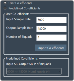
A screenshot of a computer Description automatically generated with medium confidence

After adding a new “Ssrc lir Int” object and selecting “User Coefficients Mode”, if the coefficients are not imported, the following message will be displayed on various operations such as “Save”, “Edit Device”, “Copy Core Objects” and “Paste Core Objects”. After importing coefficients, the user can perform the required operation.
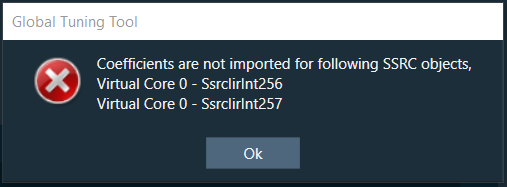
Graphical user interface, text, application Description automatically generated

Predefined Coefficients mode: In this mode, the xAF dll is used to read the input sample rate, output sample rate, and the number of biquads. When a value in the combo box is selected, the xAF dll is also used to fetch the corresponding coefficients.

Biquad Co-efficient has to be re-imported whenever the mode is switched between Predefined Co- efficient mode to User Co-efficient mode.
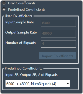
A screenshot of a computer Description automatically generated with medium confidence

For these pre-defined coefficients, the quality measures are as follows:

  • Signal to noise ratio: 80 dB
  • Total harmonic distortion: 2e-3f
  • Spurious free dynamic Range: 59 dB
  • Total harmonic distortion plus noise: -60 dB
  • Frequency response flatness: 3 dB

Output block length (Displayed as a read-only field) = (Output sample rate /Input sample rate) * Input block length.

Float to Fixed

Float to Fixed core object accepts audio buffers that are in floating point format and outputs buffers that are in fixed point format (16-bit, 24-bit, 32-bit etc).
Graphical user interface, text Description automatically generated

  • # of Channels is configurable. No of Input channels = No of Output channels
  • The user can configure the scalar value to indicate what fixed point format is required. This scalar value is multiplied by the floating point input samples to convert them to fixed point.
    For example, to convert from float to 32 bit fixed point, this scalar value must be:
    (1 << (32-1) – 1) = 2,147,483,647
  • In order to make routing from any core object to Float2Fixed object both the source core object and Float2Fixed core objects sample rate and block length should match.

Float To Fixed core object is enabled for audio libraries version 16 and greater.
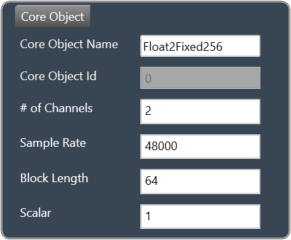
Graphical user interface, application Description automatically generated

Fixed to Float

Fixed to Float core object accepts audio buffers that are in fixed point format (16-bit, 24-bit, 32-bit, etc) and outputs buffers that are in floating point format.
Graphical user interface, text Description automatically generated

  • # of Channels is configurable. No of Input channels = No of Output channels.
  • The user can configure the scalar value to suit the fixed point format of the input samples. The reciprocal of this scalar value is multiplied by the fixed point input samples to convert them to floating point.
    For example, to convert from 32 bit fixed point to float, this scalar value must be:
    (1 << (32-1) – 1) = 2,147,483,647
  • In order to make routing from any core object to Fixed2Float object both the source core object and Fixed2Float core objects sample rate and block length should match.

Fixed To Float core object is enabled for audio libraries version 16 and greater.
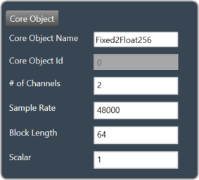
Graphical user interface, application Description automatically generated

Nan Detector

The NaN (Not a Number) detector core object detects NaN from input samples and informs the platform using an xTP command if NaN is found. The xTP command will inform about the core id, core object instance id and channel index, so that platform can react accordingly by muting or resetting states. The input samples are copied to the output without doing any other processing. The number of output channel(s) is always same as the number of input channel(s).
Graphical user interface, text Description automatically generated

  • # of Channels is configurable. No of Input channels = No of Output channels.
  • Block length and Sample rate are configurable.
  • The number of input channels is user configurable and ranges from 1 to 255.
  • This core objects’ block length and sampling rate are the same at both input and output side.
  • Block length is configurable in the range of 4 to 4096 samples.
  • Sample rate is configurable in the range of 8 kHz to 192kHz.

In order to make routing from any core object to NaN Detector, both the source core object and NaN Detector core objects sample rate and block length should match.

NaN Detector core object is enabled for audio libraries version 19 and greater.
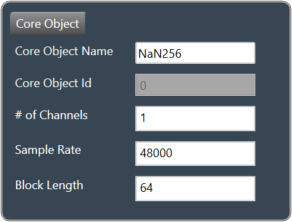
A screenshot of a computer Description automatically generated with medium confidence

Core Objects Validation

When the GTT is loaded with a version of the xAF library lower than 13. If a user tries to open a device view that contains core objects other than a XAF instance, they will see the following error message.
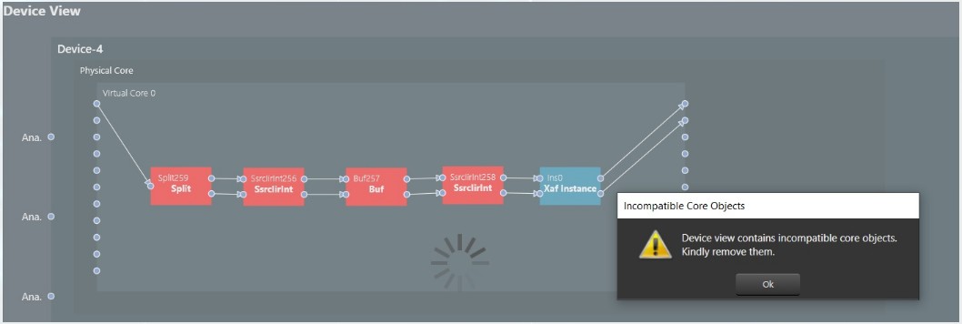
Graphical user interface, diagram Description automatically generated

Aside from the Xaf instance, every other core object will be red.
Graphical user interface Description automatically generated

Overview

This guide explores a comprehensive library of audio algorithms from Harman. It includes over 90 algorithms that can be used to create new, flexible audio processing units (Compound Audio Objects). These CAOs can be fine-tuned, protected with passwords, and shared as easily as any individual audio object.

For all Audio Objects, inside their respective tuneXTP() methods, the received tuning data is NOT checked for valid range limits.
– If the Audio Object (AO) is tuned from GTT, the GTT ensures that the tuning parameters remain within the range prescribed by the toolbox methods.
– If the Audio Object (AO) is tuned using methods other than GTT, like SVE or xTP tuning, it is the responsibility of those entities to ensure that the tuning parameter values remain within the valid range as mentioned in the Audio Object Description User Guide.

The audio objects are categorized into the following groups in the GTT.

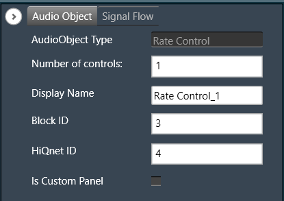
Rate Control

The Rate Control audio object controls the rate at which control signals can pass through the object. This is implemented by blocking the controls for a duration that is specified as a tuning parameter.

Rate control Properties

Below table describes the audio object properties and functionalities.

Properties Description
Number of controls Enter the number of control inputs.

The number of control outputs is always 2. The index of the pin (which receives the first control signal) is sent out on the left output pin first and then the control signal itself is sent on the right output pin.

  • Range: 1 to 255
  • Data type: xFloat32
  • Default: 1
Display Name Display name of the Rate control audio object in signal flow design. It can be changed based on the intended usage of the object.

Mode

There are currently no modes available for the Rate control audio object.

Additional parameters

There are no additional parameters available for the Rate control audio object.

Tuning Parameters

There are blocking times associated with each control input pin which could be changed as a tuning parameter.

Parameter Description Data Type Range Default Unit
BlockingTime Time for which any new control signal is blocked xFloat32 0 – 60 0 seconds

Control Interface

There are no control parameters available for the Rate control audio object.

Native Panel

Rate control audio object does not support a native panel.

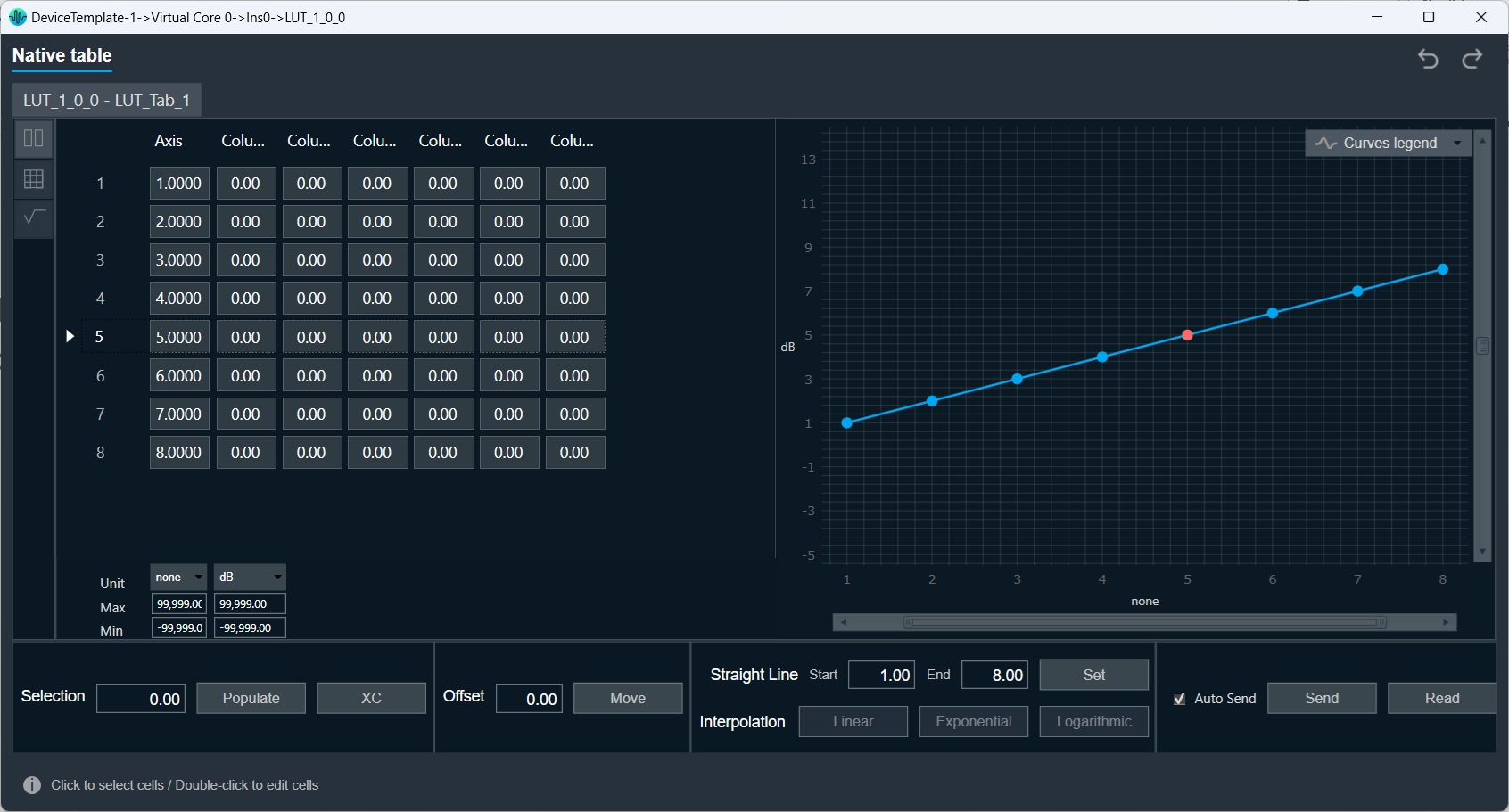
Lookup Table (LUT) Panel

LUT object supports native panel.  Double-click on the LUT object to open the native panel. Set the values accordingly.

Redo/Undo: The redo and undo functions enable you to rollback or repeat the modifications made to panel cell values, units, minimums, and maximums.

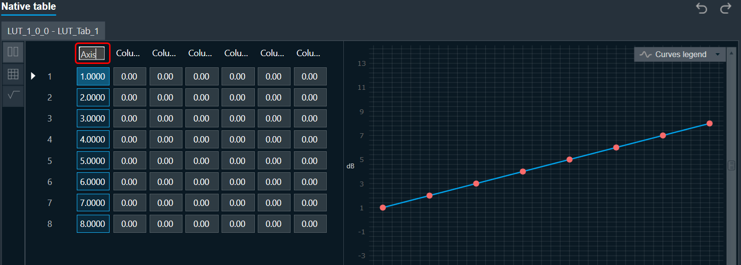
Customizable Axis Label: The customizable axis label allow to change the axis label name. Double-click on axis label will show textbox where you can change axis label name.