Interface objects category contains following audio objects.
ControlOut
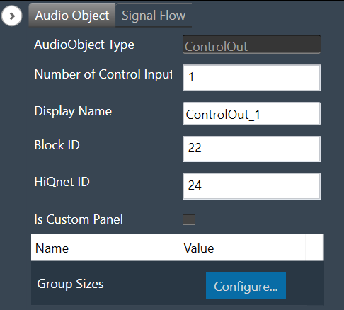
The ControlOut audio object is a framework level object, that ties directly with the framework’s control system. The purpose is to take control values from an xAF instance (AudioProcessingBase) and make them available externally.
The ControlOut audio object accepts any combination of controls – single or block.
Use Case: This object can be deployed whenever the framework wants to access any control value of a signal flow. The platform may want to access these values from the framework.
ControlOut Properties
Below table provides the details about ControlOut object properties and functionality.
| Properties | Description |
| Number of Control Input | The number of control Input signals is configurable.
|
| Display Name | Display the name of the ControlOut object in the signal flow design. It can be changed based on the intended usage of the object. |
Mode
There are no modes available for the ControlOut object.
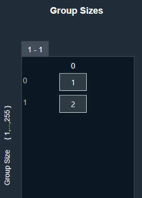
Additional Parameters
| Parameters | Description | |
| Group Sizes | This is an additional parameter which is an array with a length equal to NumElements
Each value in this array is the size of the corresponding control. Example: [1,2] would mean the first control input is a single control, but the second is a block control of size 2. |
 |
Tuning Parameters
There are no tuning parameters available for the ControlOut object.
Control Interface
There are no control parameters available to control the functioning of this object.
Native Panel
ControlOut audio object does not support the native panel.
ControlIn
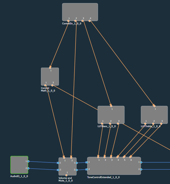
The ControlIn audio object is deployed to connect the external control signals to the audio objects used in the signal flow. Each framework instance can have only one instance of this ControlIn object. This object serves as the consolidation point for all the control inputs for the framework instance.
Use Cases:
- Use case 1 –Central volume control received (0 to 100% volume) from the Head unit will be forwarded to the controlIn AO. User can design the signal flow using LUT to convert the percentage volume to db unit and send it to Volume AO to manipulate the audio signals.
- Use case 2 – Bass and treble input from the user can be converted to Frequency, Gain, and Quality factor for Tone control audio objects to give the desired effect for the audio signal.
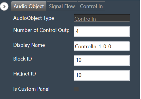
ControlIn Properties
Below table provides the details about ControlIn object properties and functionality.
| Properties | Description |
| Number of Control Output | The number of control output signals is configurable.
|
| Display Name | Display the name of the ControlIn object in signal flow design. It can be changed based on the intended usage of the object. |
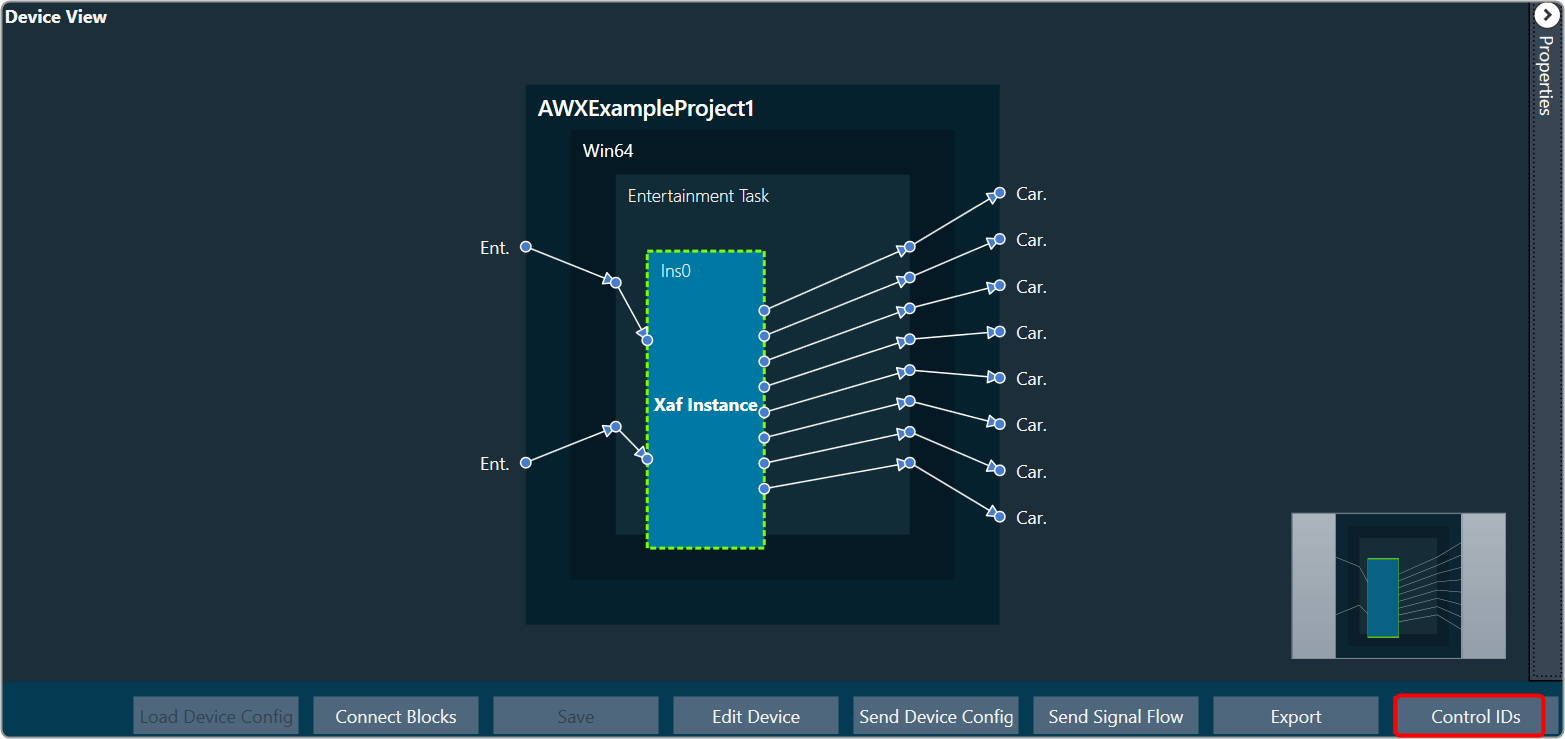
Additionally, in the ControlIn object, you can configure the Control ID for each control pin.
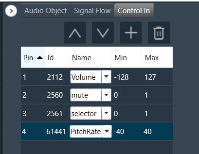
The Control IDs can be selected from the available list or you can add the new custom Control IDs. For more details on adding and editing control ID, refer to Control IDs.
Mode
There are no modes available for the ControlIn object.
Additional Parameters
There are no additional parameters available for the ControlIn object.
Tuning Parameters
There are no tuning parameters available for the ControlIn object.
Control Interface
The ControlIn object passes through the control signals received from the framework instance on the configured pins. Additionally, there are no control parameters available specifically to control the functioning of this object.
Native Panel
ControlIn object does not support the native panel.
Mixer Objects
Mixer objects category contains following audio objects.
FilePlayer
The FilePlayer audio object is used to read the audio content from a file and present them in real time on the output channels. Additionally, this audio object can also be used to add or mix the file content with the audio fed into the input channel buffers of this object.
A background thread is used to read the file contents in bulk and place them in the intermediate cache buffer, while in the main thread, the required audio data (of framework block length size) is copied from the intermediate cache buffer to the output channel buffers. The background thread periodically checks for the number of samples available in the cache buffer and replenishes the needed files.
Use Case: The FilePlayer has following use case.
- Stream wav files from local filesystem in realtime
- Resample to target sample rate if needed
- Option to support play speed from 0.1 to 10
- Option to repeat play-back in loop mode indefinitely or for a fixed number of times
- Option to insert configurable silence period in between the file play-back in loop mode
- Shall support option to disable / enable pitch shifting (linear and polyphase)
- Shall support mixing the file content with the output of another AO
- Support configurable number of output channels (up to 16)
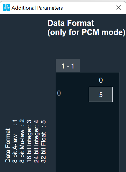
- Support WAV / PCM Files configurable during design time. Furthermore, WAV / PCM files with all of these data types are supported.
- 8 bit mu-law
- 8 bit A-law
- 16 bit integer
- 24 bit integer
- 32 bit float
Internally, all samples are converted to 32 bit floating point numbers. For both the 8 bit command formats, the conversion is done via a lookup table with 256 entries. This look-up table is filled based on the encoding format.
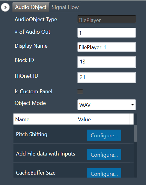
File Player Properties
| Properties | Descriptions |
| # of channels | The number of channels are configurable.
|
| Display Name | Display the name of the FilePlayer audio object in signal flow design. It can be changed based on the intended usage of the object. |
| Object mode | The object has two modes.
|
| Additional Parameters |
|
Mode
FilePlayer audio object supports two different modes of operation. The audio object can read from both WAV and PCM files.
- WAV (Default): The WAV file contains a header that has the necessary details about the stored audio content in the file
- PCM: the PCM file contains only the audio data and the details such as sampling rate and data format of the stored audio data must be provided separately.
Additional Parameters
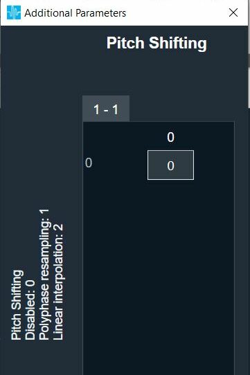
The FilePlayer audio object can be configured with the following additional parameters:
| Parameter | Descriptions | |
| Pitch shifting | This feature is provided to increase or decrease the playing speed (sample rate at which the content is played).
|
 |
| Add file data with inputs | If this feature is enabled, an equal number of input channels will be supported.
Add the content of the audio file with the output of previous AO to generate the output. By default, the AO will have only output channels and no input channels.
|
 |
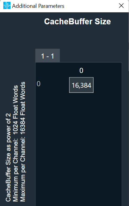
| CacheBuffer size | Allocate internal memory for reading data in the background thread.
If the background thread is having significantly lower priority, the buffer underrun is likely to occur for lower cache sizes. In such cases, the cache buffer size shall be increased. |
 |
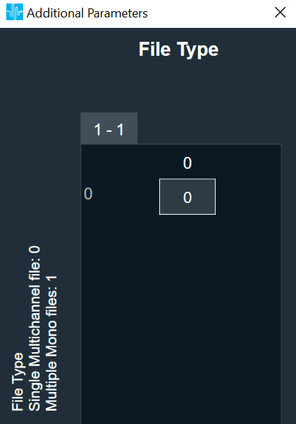
| File Type | The object supports the below files:
|
 |
| Data format (only for PCM mode) |
|
 |
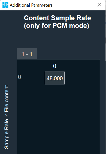
| Content Sample Rate (only for PCM mode) | All sample rates supported by framework shall be supported
Default sample rate is 48000 Hz. |
 |
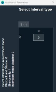
| Select Interval type | The way the interval duration is to be used can be configured here.
|
 |
| Enable Loop count | This parameter is used to configure if the loop count feature is to supported.
|
 |
Tuning Parameters
Below table describes the tuning parameters of FilePlayer audio object.
| Parameters | Description | Unit | Range | Default |
| Ramping Params Sub block: This subblock has ramping related tuning parameters applicable to all the channels. All the parameters in this sub-block as stored as unsigned integers. | ||||
| Fade-in time | Applied for control change from Stop / Pause to Play
This period needs to be less than the file playback duration. |
ms | 0 to 1000 | 100 |
| Fade-in type | Linear type only is implemented
|
None | 0 or 1 (Enum) | 0 |
| Fade-out time | Applied for control change from Play to Stop / Pause
The sum of fade-out delay and fade-out time needs to be less than the file playback duration. |
ms | 0 to 1000 | 100 |
| Fade-out type | Linear type only is implemented
|
None | 0 or 1 (Enum) | 0 |
| Fade-out delay | Delay period before starting fade-out process
The sum of fade-out delay and fade-out time needs to be less than the file playback duration. |
ms | 0 or 100 | 0 |
| Quick Fade-out time | Applied when play command is received during fade-out or fade-out delay phase to quickly end the fade-out phase and start playback. Also quick fade-out is applied only when this value is less than fade-out time. By default, this feature is disabled as the default value is not less than the fade-out time. Only linear ramping is applied. | ms | 0 to 1000 | 1000 |
| Pitch ramp time | This parameter is available only when pitch shifting is enabled and is applied for any change in play speed value
This period needs to be less than the file playback duration. |
ms | 0 to 100 | 0 |
| Pitch ramp type | This parameter is available only when pitch shifting is enabled. Linear type only is implemented.
0 – Linear 1 – Exponential (not implemented) |
None | 0 or 1 (Enum) | 0 |
| File_Config sub block: There is a separate file configuration sub block for each file. In SingleMultiChannel mode, only one sub block is present whose parameters are applicable for all the channels. In MultipleMonoFiles mode, each file has its own sub block where the parameters in each sub block is applicable for the respective mono channel. | ||||
| File ID | The files shall be placed in the device folder using FileController. | None | 1 to 255
Data Type: Unsigned Integer |
1 |
| Play Setup |
|
None | 1 to 5 (Enum)
Data Type: Unsigned Integer |
1 |
| Start Position | Start position in percentage from where file will be played. In LOOP mode, this is applicable only at the start of the play and not on every loop back | None | 0 to 99.99
Data Type: Float |
0 |
| Function | 1 – STOP
2 – PLAY 3 – RESET (STOP and PLAY) 4 – PAUSE |
None | 1 to 4 (Enum)
Data Type: Unsigned Integer |
1 |
| Interval*
or Silence
|
This parameter is available only when interval type is not disabled in the ‘Select Interval Type’ additional parameter. Based on the option chosen in the additional parameter, one of the following two parameters will be available: Interval OR Silence
Interval: When ‘Select Interval Type’ = 0. This is applicable only in Intermittent mode. This is the interval period at which the file will be played from the beginning periodically. Silence: When ‘Select Interval Type’ = 1. This is applicable only in Loop mode. This is the silence period inserted after each file playback. When the parameter value is zero, the loopback is seamless. |
Interval: s
Silence: ms |
Interval:
Silence:
|
Interval: 10
Silence: 0 |
| Loop Count | This parameter is available only when Loop count is enabled in the additional parameter. If not enabled, the file playback is repeated indefinitely.
Also, this parameter is applicable only in loop mode. If the value is zero, the file playback is repeated indefinitely; else the file playback is repeated for the given number of times. When in loop play mode, this parameter value is applied only when the AO is in stop state and not when it is in play state. |
None | 0 to 10000
Data Type: Unsigned Int
|
0 |
| Play Speed** | This is available only when pitch shifting is enabled. This is the play speed at which the file is played | None | 0.1 to 10
Data Type: Float |
1 |
* The interval period normally shall be greater than the waveform playback duration. If the interval is less than or equal to the waveform playback duration, glitch / pop noise with a short mute period is present.
** Playback Duration = File Duration / Play Speed
State Parameters
| Parameters | Description | Unit | Range | Default |
| Function State Sub block: This subblock has the function state parameter for each file. This parameter is used to configure and readback the present function state of the given channel(s). In SingleMultiChannel mode, only one state parameter is present that is applicable for all the channels. In MultipleMonoFiles mode, each file has its own state parameter applicable for the respective mono channel. | ||||
| Function_Ch | 1 – STOP
2 – PLAY 3 – RESET (STOP and PLAY) 4 – PAUSE |
None | 1 to 4 (Enum)
Data Type: Unsigned Integer |
1 |
| File State Sub block: This subblock has the file state parameter for each file. This parameter is used only to readback the present file state of the given file(s) and any parameter change is ignored. In SingleMultiChannel mode, only one state parameter is present for the given file. In MultipleMonoFiles mode, each file has its own state parameter. | ||||
| File_State | This reflects the present file status.
0 – FILEPLAYER_IDLE 1 – FILE_READY 2 – FILE_PLAY_ACTIVE 3 – FILE_STOPPED 4 – FILE_OPEN_ERROR 5 – FILE_PAUSED |
None | 0 to 5 (Enum)
Data Type: Unsigned Integer |
0 |
Control Interface
Control Inputs
The FilePlayer has the following Control Inputs.
| Control Input | Description | Size in Float Words | Range |
| Block Control: There are FOUR control pins under this block control pin. For SingleMultiChannel mode, only one set of block control input needs to be sent. For Multiple Mono mode, for each channel a set of block controls needs to be sent separately. | |||
| Channel ID | Channel ID to associate with each output channel. | 1 of 4 | 1 to 16 |
| File ID | The files shall be sent through the FileController. | 2 of 4 | 1 to 255 |
| File Setup |
|
3 of 4 | 1 to 5 |
| Start Position | Start position in percentage from where file will be played. | 4 of 4 | 0 to 99.99 |
| Function Control Pins: This control pin is used to change the function of the AO. For AOs configured in Single Multichannel mode, only one (N = 1) control input pin will be available applicable to all the channels. For AOs configured in Multiple Mono mode with N channels, there will be equal number (N) of control inputs for each file (channel). |
|||
| Function | 1. STOP (default on boot-up)
2. PLAY 3. RESET (STOP followed by PLAY) 4. PAUSE |
N | 1 to 4 |
| Interval / Silence Control Pins: Only one of them – Interval or Silence pin – can be made available based on the configuration in the additional parameter – ‘Select Interval Type’. For AOs configured in Single Multichannel mode, only one (N = 1) control input pin will be available applicable to all the channels. For AOs configured in Multiple Mono mode with N channels, there will be equal number (N) of control inputs for each file (channel).
Interval control pin is applicable only in INTERMITTENT play mode and is used to change the interval period of the playback. Silence control pin is applicable only in LOOP play mode and is used to change the required silence period after each file playback. |
|||
| Interval | This is the interval period at which the file will be played from the beginning periodically. | N | 0.01 to 1000 s |
| Silence | This is the silence period inserted in between consecutive file playback. | N | 0 to 1000 ms |
| Loop Count Pins: These pins are available only when loop count feature is enabled in the additional configuration parameter. If is is not configured, the file playback is repeated indefinitely.
For AOs configured in Single Multichannel mode, only one (N = 1) control input pin will be available applicable to all the channels. For AOs configured in Multiple Mono mode with N channels, there will be equal number (N) of control inputs for each file (channel). |
|||
| Loop count | This is the number of times the file playback is to be repeated. If the value is zero, the playback is repeated indefinitely. When in loop play mode, this control value is applied only when the AO is in stop state and not when it is in play state. | N | 0 to 10000 |
| Pitch Control Pins: This control pin(s) is/are available only when pitch shifting is enabled and is used to change the play speed of waveform playback. For AOs configured in Single Multichannel mode, only one (N = 1) control input pin will be available that is applicable to all the channels. For AOs configured in Multiple Mono mode with N channels, there will be equal number (N) of control inputs for each file (channel). |
|||
| Play Speed | This is the play speed at which the file is played.
The control input is in terms of play speed. |
N | 0.1 to 10 |
Control Outputs
The FilePlayer has the following Control Outputs.
| Control Output | Description | Size in Float Words | Range |
| There are two control output pins – either two single control pins or two block control pins.
When the AO is configured in Single Multichannel mode, two single control (N = 1) pins are available for the control outputs listed below. When the AO is configured in Multiple Mono mode with N channels, two block control (N) pins are available for the control outputs listed below. |
|||
| Play Position | During active playback, for every audio interrupt, the AO outputs the play position in terms of percentage covered in the file. | N | 0 to 99.99 |
| File State
|
Whenever there is a change in the file status, the AO outputs the file state:
0 – FILEPLAYER_IDLE 1 – FILE_READY 2 – FILE_PLAY_ACTIVE 3 – FILE_STOPPED 4 – FILE_OPEN_ERROR 5 – FILE_PAUSED |
N | 0 to 5 |
In Single Multichannel file mode, mono file also can be played.
In Multiple Mono file mode, all the files need to be mono files. In WAV mode, if the file is seen having more than 1 channel, that file will be ignored. In PCM mode, the file will be taken as a mono file and played leading to improper output.
In Multiple Mono file mode, all the mono files need to be in the same data format and sampling rate. If files with different data format are used, the data format of the last configured file will be considered and the same will be applied to all other mono files leading to improper output.
The FilePlayer audio object can be configured with multiple channels. The channel count of the object and the number of channels in the wav file may differ. Error message is returned if extra channels are present in the audio file. If extra channels are configured in the object, those extra channels are filled with silence.
In cases with low intermediate cache buffer size, the background thread need to run frequently to replenish the data available in the cache buffer. If distortion is observed with low cache size, buffer underrun could be the cause and background thread shall be moved to higher priority or the cache buffer size shall be increased.
It is recommended to configure the sound card block length to less than the cache buffer size under Sound Card Configuration while using IVP.
The actual memory required for the supporting the intermediate cache buffer size will be slightly more than the size specified in the additional parameters as it is required to store extra data (of polyphase filter order) for supporting filtering. The memory latency table shall be referred for exact memory requirements.
In Single Multichannel file, let the number of files present in the file content be M and the number of channels configured for the object be N.
In WAV mode:
– If M = N, all the N channels will be played with the file content.
– If M < N, first M channels buffers will be populated with the file content and the remaining N-M channels will be muted.
– If M > N, none of the channels will be played and all channels will be muted.
In PCM mode:
– If M = N, all the N channels will be played properly with the file content.
If M != N, the file will be taken as a N channel file and played leading to improper output.
Native Panel
FilePlayer audio object does not support native panel.
Source Objects
Source objects category contains following audio objects.
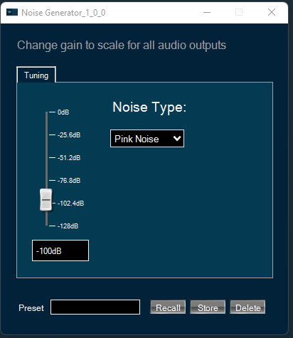
Noise Generator Panel
The Noise Generator Panel is used to change noise type and noise level. In SFD you can configure several output channels. The same noise type and level will be applied to each channel.
Noise Generator panel works only with PRO object modes “Pro-Prbs” and “Pro-Lcg”. Panel will not work in “WhiteNoise” and “PinkNoise” object modes.
Changing Noise Level
You can change the noise level by three ways:
- Using slider button: Select the slider to adjust the value.
- Using mouse scroll: Use mouse scroll to adjust the value.
- Enter an exact value in the text box.
Changes will take place after hitting the “Enter” key or by moving the focus away from the text box.
Changing Noise Type
You can change the noise type by clicking on the combo-box and selecting the type.
Possible noise generator types are:
- White Noise
- Pink Noise
Delay Panel
The Delay panel associated with Delay audio object. The Delay panel is used for changing the delay of the signal for each channel.
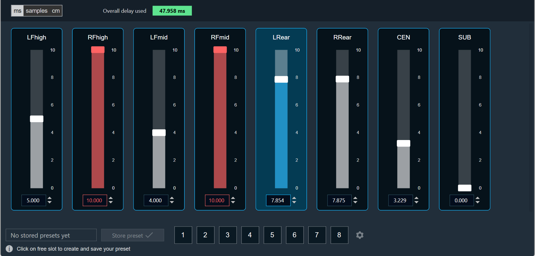
- Maximum / Minimum Delay Value: The maximum and minimum delay values are from corresponding state variable of Delay.
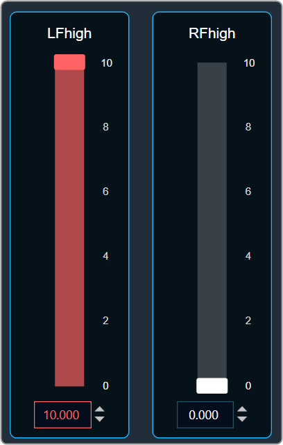
- Threshold Values: The maximum and minimum threshold values are derived from the GTT in the ParameterStore. Once the threshold value is reached, the Delay value bar will change to red color.
- Maximum threshold value: 95 %
- Minimum threshold value: Not set
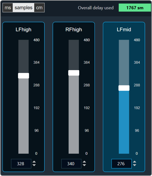
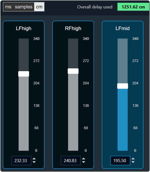
- Changing Units: You can switch between the milliseconds, samples, centimeters.
| Milliseconds
|
Samples
|
Centimeters
|
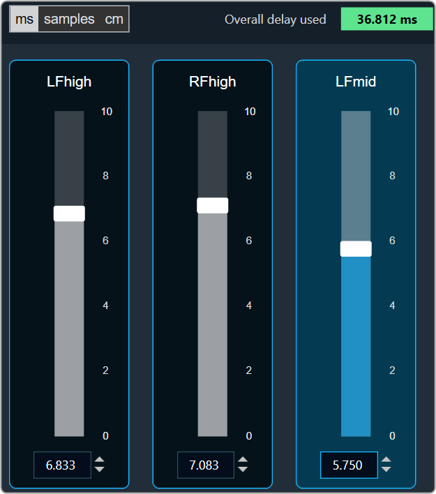
- Object Mode (Instant/CrossFade): In GTT the delay values are derived from the parameter store. Each channel’s delay value is configurable from 0 to Max Delay.
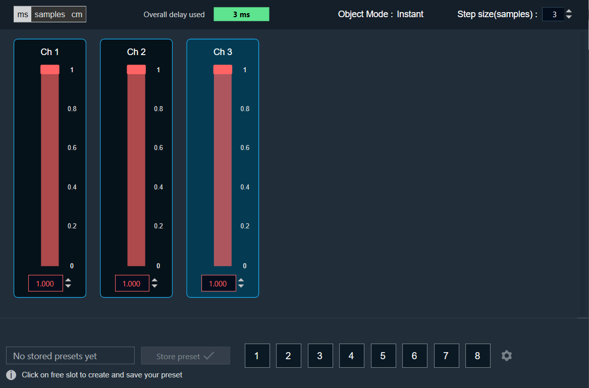
- Object Mode (DelayPool): In GTT the delay values are derived from the parameter store. When the object mode is set to DelayPool, the “Overall delay used” shown is sum of delay values of all the channels. Sum of the delay of channels is expected not to exceed Max Delay. Changes in delay values are accepted by the audio object only when sum does not exceed Max Delay.
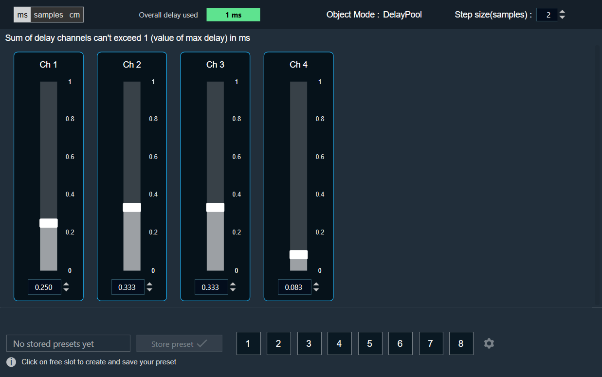
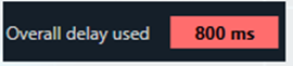
You can find the overall “delay value used” at the top of the Delay panel. The value in text area changes its color depending on the percentage of the maximum overall delay value.
-
- Up to 80 % of the delay pool
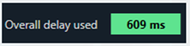
- From 80 % – 100 % of the delay pool

- 100 % of the delay pool
- Up to 80 % of the delay pool
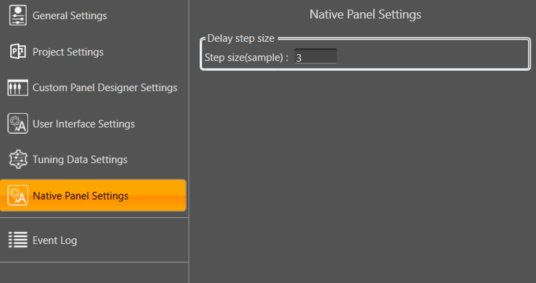
- Step Size for delay: In the application settings, you can change the global step size. The local step size in the delay audio object is derived from the global step size specified in the application settings. When you change the value of the local step size, the global step size value is no longer used.
To change the Delay Value
You can change the delay value in four ways:
- Using slider button: Select the slider to adjust the delay value.
- Using mouse scroll: Hover on the respective column and use mouse scroll to adjust the delay value.
- Using text box: Select the respective column and enter the dB value within the specified minimum and maximum range. Once you’ve entered the value, press Enter, and the slider will automatically adjust based on the input.
- Using the increase and decrease buttons
 the delay calculated step value (based on max delay (ms)).
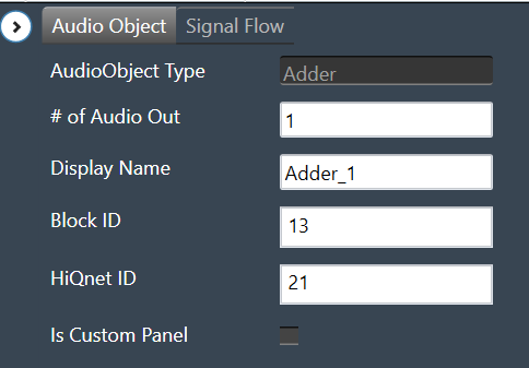
Adder
The Adder audio object sums the samples of 2 audio channel input buffers and writes their sum to the output buffer. Thus, the number of input channels is always twice the number of output channels:
This module sums the pairwise contents of m_NumAudioIn audio buffer channels and writes the result to the output buffer. For this audio module, m_NumAudioIn is always double m_NumAudioOut.
Use Case: This object can be deployed whenever the sum of two audio channels or pairs of audio channels is required in the audio pipeline.
Adder Properties
Below table describes about the Adder audio object properties and functionality.
| Properties | Description |
| # of Audio Out | Adder audio object has a number of input channels that is double the number of output audio channels.
The number of output channels is configurable in SFD, and the number of input channels is derived accordingly. |
| Display Name | Display the name of the Adder audio object in signal flow design. It can be changed based on the intended usage of the object. |
Mode
There are no mode available for Adder audio object.
Additional Parameters
There are no additional parameters available for Adder audio object.
Tuning Parameters
There are no tuning parameters available for Adder audio object.
Control Interface
There are no control parameters available for Adder audio object.
Native Panel
Adder audio object does not support native panel.
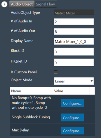
Matrix Mixer
The Matrix Mixer audio object is used to calculate weighted output audio based on a combination of input audio. In addition to this, the object also supports delay of input channels.
Use Case: The Matrix Mixer takes in a configurable number of input and output channels. Each output of this object is a weighted sum of all the input channels. Any input can get summed into any output with or without a delay.
Matrix Mixer Properties
Below table describes about the Matrix Mixer audio object properties and functionality.
| Properties | Description |
| # of Audio In | Number of input channels.
|
| # of Audio Out | Number of output channels.
|
| Display Name | Display the name of the Matrix Mixer audio object in signal flow design. It can be changed based on the intended usage of the object. |
| Object Mode | Matrix Mixer object operates in one of the following two modes.
|
This object supports DelayMatrixMixer function.
Mode
The Matrix Mixer object supports two different modes of operation.
| Mode | Description |
| Linear (Default) | In this mode, the gain values (channel weights) are configurable on a linear scale in the range -10 to +10. |
| dB | In this mode, the gain values are configurable in decibels in the range between -128 dB to 20 dB and these decibel values are converted to linear values by xAF by the formula given below before multiplying with input channel samples.
|
Additional Parameters
The Matrix Mixer audio object can be configured with the following additional parameter:
| Parameter | Descriptions | |
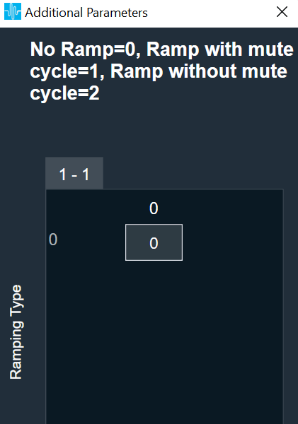
| No Ramp = 0,
Ramp with mute cycle = 1, Ramp without mute cycle = 2 |
The mixer also has three ramping types that can be configured through an additional number of parameters:
In the SFD, you can set the number of input and output channels. These channels do not need to be identical. The mode and ramping type are also configurable in the SFD. In the GTT, the Matrix Mixer exposes variables for tuning, for each input and output channel. You can modify these to change the weights used to scale the input channels. In the ramp modes, additional ramp time and control variables are exposed as explained above |
 |
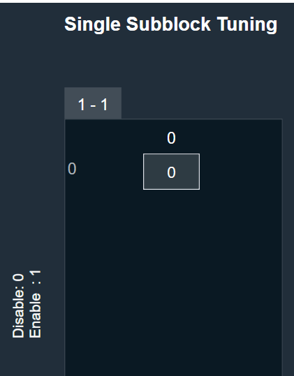
| Single Subblock Tuning | The object has an additional configuration variable “Single Subblock Tuning” to enable or disable it. On enabling it, allows contiguous memory allocation and the gain values can be tuned as single subblock.
By Default, Single Subblock Tuning is disabled. |
 |
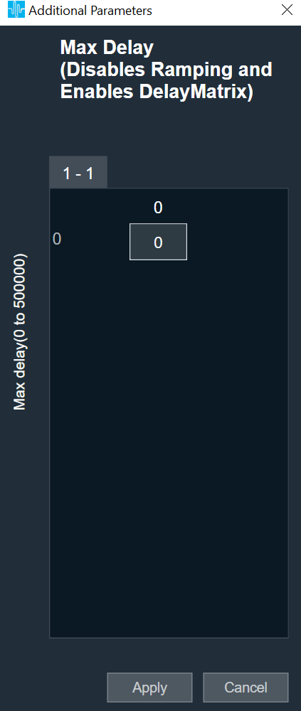
| Max Delay |
The object has an additional configuration variable “Max Delay”.
Range: The value ranges from 0 to 500000 samples. By default, it is set to 0 samples. Ramp with mute cycle and Ramp without mute cycle types are not supported when Max delay is greater than 0. There is no native panel for DelayMatrixMixer |
 |
Tuning Parameters
The GTT can read or write into parameter memory using tuning command respectively. The memory stores a value per output channel that has a gain value to be multiplied by per input channel based on the mode. These parameters are tunable. Assuming the object is composed of NIn input channel and Nout output channels, the description will look as follows (depending on gain type).
For No Ramp mode
Parameter memory for “No Ramp” mode with Linear Gain
|
Linear Gain |
||||||||
| Sub-block ID
(Single Subblock tuning : Disabled) |
Sub-block ID
(Single Subblock tuning : Enabled) |
Name | Type | Unit | Min | Max | Default Value | Description |
| 0 | 0 | float | -10 | 10 | 0 | NIn gain inputs for Ch0 output | ||
| 1 | 0 | NIn gain inputs for Ch1 output | ||||||
| … | 0 | … | ||||||
| Nout-1 | 0 | NIn gain inputs for ChNout-1 output | ||||||
Parameter memory for “No Ramp” mode with Logarithmic Gain
|
Logarithmic Gain |
||||||||
| Sub-block ID
(Single Subblock tuning : Disabled) |
Sub-block ID
(Single Subblock tuning : Enabled) |
Name | Type | Unit | Min | Max | Default Value | Description |
| 0 | 0 | float | dB | -128 dB | 20 dB | -128 dB | NIn gain inputs for Ch0 output | |
| 1 | 0 | NIn gain inputs for Ch1 output | ||||||
| … | 0 | … | ||||||
| Nout-1 | 0 | NIn gain inputs for ChNout-1 output | ||||||
For Ramp with mute cycle mode
It has an additional ramp time configurable parameter.
Parameter memory for “Ramp with mute cycle” mode ramping with Linear Gain
|
Linear Gain |
||||||||
| Sub-block ID
(Single Subblock tuning : Disabled) |
Sub-block ID
(Single Subblock tuning : Enabled) |
Name | Type | Unit | Min | Max | Default Value | Description |
| 0 | 0 | float | -10 | 10 | 0 | NIn gain inputs for Ch0 output | ||
| 1 | 0 | NIn gain inputs for Ch1 output | ||||||
| … | 0 | … | ||||||
| Nout-1 | 0 | NIn gain inputs for ChNout-1 output | ||||||
| Nout | 1 | Ramp Time | float | ms | 0 | 5000 | 500 | The time it takes for the ramp to complete. This value is split in half between muting and unmuting stages of the output signal. |
Parameter memory for “Ramp with mute cycle” mode ramping with Logarithmic Gain
|
Logarithmic Gain |
||||||||
| Sub-block ID
(Single Subblock tuning : Disabled) |
Sub-block ID
(Single Subblock tuning : Enabled) |
Name | Type | Unit | Min | Max. | Default Value | Description |
| 0 | 0 | float | dB | -128 dB | 20 dB | -128 dB | NIn gain inputs for Ch0 output | |
| 1 | 0 | NIn gain inputs for Ch1 output | ||||||
| … | 0 | … | ||||||
| Nout-1 | 0 | NIn gain inputs for ChNout-1 output | ||||||
| Nout | 1 | Ramp Time | float | ms | 0 | 5000 | 500 | The time it takes for the ramp to complete. This value is split in half between muting and unmuting stages of the output signal. |
For “Rampwithout mute cycle” mode
It has an additional ramp characteristics parameters which are ramp down time, ramp up time, ramp down shape and ramp up shape.
Parameter memory for “Ramp without mute cycle” mode ramping with Linear Gain
| Linear gain | ||||||||
| Sub-block ID
(Single Subblock tuning : Disabled) |
Sub-block ID
(Single Subblock tuning : Enabled) |
Name | Type | Unit | Min | Max | Default Value | Description |
| 0 | 0 | float | -10 | 10 | 0 | NIn gain inputs for Ch0 output | ||
| 1 | 0 | NIn gain inputs for Ch1 output | ||||||
| … | 0 | … | ||||||
| Nout-1 | 0 | NIn gain inputs for ChNout-1 output | ||||||
| Nout | 1 | Ramp down Time | float | ms | 0 | 5000 | 500 | The time it takes for the ramp to complete. |
| Nout | 1 | Ramp up time | float | ms | 0 | 5000 | 500 | The time it takes for the ramp to complete. |
| Nout | 1 | Ramp down shape | Int | 0 | 2 | 1 | Ramping shape, it can be jump (0), linear (1) and exponential (2). | |
| Nout | 1 | Ramp up shape | int | 0 | 2 | 1 | Ramping shape, it can be jump (0), linear (1) and exponential (2). | |
Parameter memory for “Ramp without mute cycle” mode ramping with Logarithmic Gain
| Logarithmic Gain | ||||||||
| Sub-block ID
(Single Subblock tuning : Disabled) |
Sub-block ID
(Single Subblock tuning : Enabled) |
Name | Type | Unit | Min | Max | Default Value | Description |
| 0 | 0 | float | dB | -128 dB | 20 dB | -128 dB | NIn gain inputs for Ch0 output | |
| 1 | 0 | NIn gain inputs for Ch1 output | ||||||
| … | 0 | … | ||||||
| Nout-1 | 0 | NIn gain inputs for ChNout-1 output | ||||||
| Nout | 1 | Ramp down time | float | ms | 0 | 5000 | 500 | The time it takes for the ramp to complete |
| Nout | 1 | Ramp up time | float | ms | 0 | 5000 | 500 | The time it takes for the ramp to complete |
| Nout | 1 | Ramp down shape | int | 0 | 2 | 1 | Ramping shape, it can be jump (0), linear (1) and exponential (2). | |
| Nout | 1 | Ramp up shape | int | 0 | 2 | 1 | Ramping shape, it can be jump (0), linear (1) and exponential (2). | |
DelayMatrixMixer
The object functions as DelayMatrixMixer with Delay Pool when the additional configuration variable “Max Delay “ is set to more than 0 samples. A “Delay” tuning parameter is added in addition to the gain parameter for each input channel. The delay buffer (of length Max Delay) is shared by all the channels. Therefore, the available delay for each channel depends on the delay values configured for the other channels. The input channels are multiplied with the channel weights and are applied with delay configured and summed at the output channel.
| Parameter | Description | Range | Default |
| Delay | Delay to be applied across each channel. | 0 to Max Delay(samples) | 0 |
| Gain | Gain to be applied across each channel | Linear : -10 to +10
dB : -128 dB to 20 dB |
Linear : 0
dB : -128 dB |
Control Interface
There are no control parameters available for Matrix Mixer audio object.