Dynamic objects category contains following audio objects.
Volume and Mute
The purpose of the Volume and Mute audio object is to control the volume or mute in the audio pipeline. Additionally, Volume block also amplitude scaling with ramps.
Use a custom native panel to change the Volume and Mute audio object parameters. The mode and tune type may also be selected at design time from within SFD.
The Volume and Mute audio object supports in-place computation based on the core type.
Volume and Mute Properties
Below table describes the Volume and Mute audio object properties and functionality.
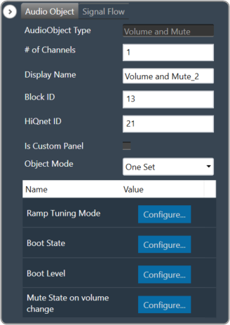
| Properties | Descriptions |
| # of Channels | In SFD, the number of channels is specified, and the number of input channels is equal to the number of output channels.
|
| Display Name | Enter the display name of the audio object. It can be changed based on the intended usage of the object. |
| Object Mode | Volume object operates in one of the three modes.
|
Mode
Volume object operates in one of the three modes.
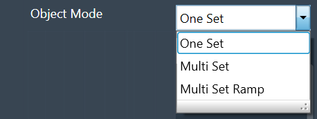
| Mode | Description |
| One Set | In this mode, the volume object exposes these six values.
These values are applied across all channels of the module. The ramping variables are only available via parameter tuning in this mode. |
| Multi Set: | In this mode, Volume, Mute, and Invert values are available per channel. One set of ramp rates and shape however is applied to all channels. The ramping variables are only available via parameter tuning. |
| Multi Set Ramp: | In this mode, Volume, Mute, Invert, Ramp Up rate, Ramp Down Rate, and Ramp shape values are all available per channel. |
Additional Parameters
Volume and Mute audio objects consist of the following additional parameters.
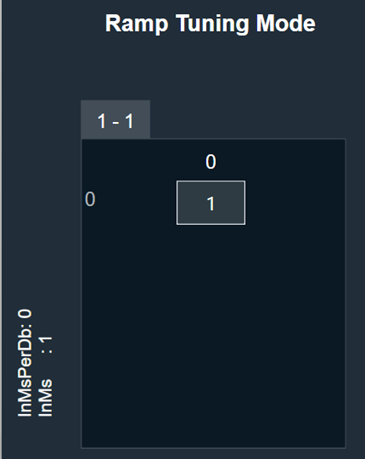
- Ramp Tuning Mode
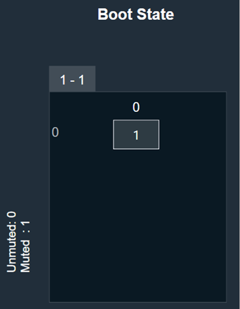
- Boot State
- Boot Level
- Mute state on volume change
| Parameters | Description | |
| Ramp Tuning Mode | Ramping is applied when a transition or change occurs and is specified in terms of rate (ms/dB) or time (ms).
|
 |
| Boot State | The boot-up or start-up state of the Volume AO can be specified in 0 or 1.
|
 |
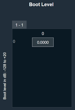
| Boot Level | The amplitude level of the Volume AO at boot-up or start-up time can be specified.
Range: -128 dB to + 20 dB The default value shall be 0 dB. |
 |
| Mute state on volume change | The desired state of the AO when the volume parameter is changed while the object is in Mute state is specified here.
|
 |
Tuning Parameters
Ramp Parameters: The Volume audio object exposes ramp rate/time settings that can be adjusted from GTT.
| Parameters | Descriptions | Range | Unit |
| Ramp Up Rate or Time | Ramp up rate in ms/dB or ramp time in ms. | 0 to 1000 | ms/dB or ms |
| Ramp Down Rate or Time | Ramp down rate in ms/dB or ramp time in ms. | 0 to 1000 | ms/dB or ms |
| Ramp Shape | The shape of the volume will change according to once a volume or mute control is triggered. |
|
Volume Parameters: The Volume object has three state parameters volume, mute, and invert (phase shift of 0 or 180) per channel.
This functionality is only triggered in the multi-set mode.
| Parameters | Descriptions | Range | Unit |
| Volume | Volume to be applied on all input channels | -128 to 20 | dB |
| Mute | Mute to be applied on all input channels | 0 or 1 | |
| Invert | If set to 1, all input channels will be multiplied by -1
If set to 0, all input channels will be multiplied by 1 |
0 or 1 |
Control Interface
The Volume control is triggered whenever a control message is addressed to the audio object. In One Set mode, the object supports two control inputs and one control output.
Control IO is not available for the other two modes.
Control Inputs
Volume and Mute object has two control inputs as follows:
| Parameters | Descriptions | Range | Unit |
| Volume | Volume to be applied on all input channels. | -128 to 20 | dB |
| Mute | Mute to be applied on all input channels |
|
None |
Control Outputs
Volume and Mute object has one control output as follows:
| Parameters | Descriptions | Range | Unit |
| Volume | Gain applied for a particular frame (blocklength of samples) | -128 to 20 | dB |
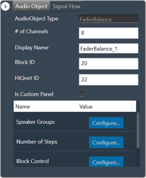
FaderBalance
The primary purpose of the Fader Balancer audio object is to optimize the audio quality within the vehicle’s cabin by adjusting the sound distribution. This audio object allows to identify the “sweet spot” of the sound by moving in the x and y directions.
The Fader Balance object has only one operating mode and has three additional configuration parameters – Speaker Groups, Number of Steps, and Block Control. Using these additional parameters, you can configure the setup during design time.
Each audio channel may belong to one or two speaker groups as set in the additional variable. Fader speaker group has the following speaker types:
- CENTER
- SIDE
- BASS
- FRONT
- REAR
Balance speaker group has the following speaker types:
- CENTER
- LEFT
- RIGHT
Each speaker type in each speaker group has its own gain table.
The output samples are generated by multiplying the input samples with the composite gain value that is a product of the gain levels of the Balance and Fader gain tables assigned to this channel and as pointed by the control inputs – Control_Balance and Control_Fader. The composite gain value is morphed to avoid pops.
Channel configuration (assignment to speaker types of the selected speaker groups), morphing time, and the gain level of each step are configurable through the xTP interface. Basically, mixing run-time tuning (add cfg params) and design-time tuning (add cfg params). GTT is used for configuration in general, and xTP is the protocol used to deliver tuning data.
Fader and Balance positions are provided through control inputs.
Fader Balance is ported from the Summit version with the following differences:
- The option for 4 modes is not supported. This shall be handled with the preset files. The number of control inputs is brought down to 2 due to this change.
- Stand-alone Fader AO and Balance AO can be achieved by configuring the additional parameters in the SFD.
- The step count is made as an additional variable instead of using the “Number of Elements” field.
- The channel configuration is done using a drop-down menu to select only one speaker type in each speaker group. This prevents the selection of multiple speaker types by mistake.
Use Case: Using this method, you can optimize the sound loudness on the left or back of the cabin.
Fader Balance Properties
Below table describes the Fader Balance audio object properties and functionality.
| Properties | Descriptions |
| # of Channels | The number of audio channels it can process is configurable in the SFD and ranges from 1 to 255. The number of audio inputs is always equal to the number of audio outputs.
|
| Display Name | Display the name of the Fader Balance audio object in signal flow design. It can be changed based on the intended usage of the object. |
Mode
There are no mode available for Fader Balancer.
Additional Parameters
| Parameters | Description | |
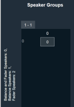
| Speaker Groups | Speaker Groups can be set to one of the following three options:
|
 |
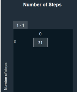
| Number of Steps | The “Number of Steps” is a common variable that controls the number of gain levels that the user can operate.
To control the gain level of fader and balance speakers the value shall be odd, and this value is common for balance and fader speaker groups. The number of steps needs to be an odd number and shall range from 3 to 65 with the default value at 31. The xAF data order is set as “xAF_ODD” to communicate to the GTT through DDF to prevent entering even numbers by the user. |
 |
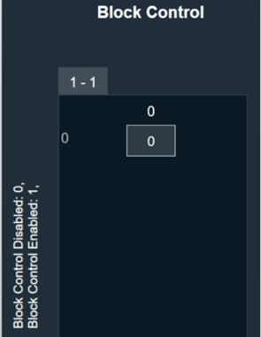
| Block Control | Block Control Disabled (0) – Default
Block Control Enabled (1) |
 |
Tuning Parameters
The following tuning parameters are available for the Fader Balancer audio object.
| Parameter Name | Description | Type | Unit | Default value |
| MorphingTime | Morphing time. The range is from 0 ms (no morphing) to 100 ms.
Morphing time follows time constant and the morphing time is denoted as M. Following is the percentage of change achieved: |
float | ms | 0.01 |
| Channel # Assignment | This parameter assigns a particular audio channel to one or none of the speaker types in each group. The following pair of speaker-type assignments is available for each channel.
|
ULong
ULong |
—
— |
BAL_CENTER
FAD_CENTER |
| BalanceCenterTable | Balance table for center speaker group. The gain value for each step is tunable.
Range: -128 to 0 dB |
float | dB | 0 |
| BalanceLeftTable | Balance table for left speaker group. The gain value for each step is tunable.
Range: -128 to 0 dB |
float | dB | 0 dB for the first (NUMBER_OF_STEPS+1)/2 steps, next are linearly decreased with equal step in dB scale to -128 dB. |
| BalanceRightTable | Balance table for right speaker group. The gain value for each step is tunable.
Range: -128 to 0 dB |
float | dB | Start from -128 dB and are linearly increased with equal step in dB scale to 0dB to (NUMBER_OF_STEPS-1)/2 step, next their value is 0 dB. |
| FaderCenterTable | Fader table for center speaker group. The gain value for each step is tunable.
Range: -128 to 0 dB |
float | dB | 0 |
| FaderSideTable | Fader table for side speaker group. The gain value for each step is tunable.
Range: -128 to 0 dB |
float | dB | 0 |
| FaderBassTable | Fader table for bass speaker group. The gain value for each step is tunable.
Range: -128 to 0 dB |
float | dB | 0 |
| FaderFrontTable | Fader table for front speaker group. The gain value for each step is tunable.
Range: -128 to 0 dB |
float | dB | 0 dB for the first (NUMBER_OF_STEPS+1)/2 steps, next are linearly decreased with equal step in dB scale to -128 dB. |
| FaderRearTable | Fader table for rear speaker group. The gain value for each step is tunable.
Range: -128 to 0 dB |
float | dB | Start from -128 dB and are linearly increased with equal steps in dB scale to 0dB to (NUMBER_OF_STEPS-1)/2 step, next their value is 0 dB. |
Control Interface
The following two control parameters are available for the Fader Balancer audio object.
- Balance – To set the Balance knob position
- Fader – To set the Fader knob position
Level Monitor
The Level Monitor is intended to measure the level of input; the audio samples are sent to the output without modification.
Use case: This object can be deployed in Level Monitor mode whenever there is a need to measure the level of signal level and in Clip Meter mode to check if the level is causing clipping. The same input is sent as output without modification.
Level Monitor Properties
Below table describes the Level Monitor audio object properties and functionality.
| Properties | Descriptions |
| # of Channels | In the Signal Flow Designer (SFD), the number of control outputs is equal to the number of audio channels. Each control output writes out the channel level/clip indication value based on the MODE selected.
|
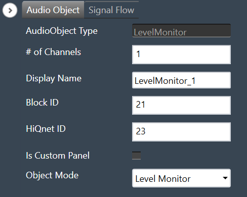
| Display Name | Display the name of the Level Monitor audio object in signal flow design. It can be changed based on the intended usage of the object. |
| Object Mode | During design time, the audio object channel can be configured in one of the two operation modes.
|
Mode
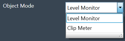
During design time, the audio object can be configured in one of the two operation modes.
- Level Monitor
- Clip Meter
| Mode | Description |
| Level Monitor | This is the default mode.
In this mode, the signal level is measured and the value is sent to the control output. |
| Clip Meter | In this mode, the object computes the signal level and compares it with the threshold set through the tuning parameters. A flag is set/reset if the signal level is above/below the threshold and this flag is sent to the control output. |
Additional Parameters
There are no additional parameters available for the Level Monitor audio object.
Tuning Parameters
Under Level Monitor mode, the following are the tuning parameters available for each channel.
| Parameter | Description | Range | Default | Data Type | Unit |
| LEV_MODE | To select the method of computation of the input signal level
In all the above types, the computed level is always presented in dB (logarithmic scale) |
0 – RMS
1 – LINEAR 2 – PEAK |
0 | Float | NA |
| DB_LEAK_PER_SEC | Amount of dB drop per second in Peak Level mode. | 1 to 60 | 30 | Float | dB |
| PEAK_HOLD_TIME | Amount of time peak is held. | 0 to 1 | 0.05 | Float | second |
Under Clip Meter mode, the following is the tuning parameter available for each channel.
| Parameter | Description | Range | Default | Data Type | Unit |
| Threshold | The threshold value for the channel to treat a signal as being clipped. | -20 to 20 | -0.25 | Float | dB |
State Parameters
Under Level Monitor mode, the following is the state parameter available for each channel.
| Parameter | Description | Range | Default | Data Type | Unit |
| LEVEL_VALUE | Measured signal level for the channel | -128 to 20 | 0 | Float | dB |
Under Clip Meter mode, the following is the state parameter available for each channel.
| Parameter | Description | Range | Default | Data Type | Unit |
| Clip Indicator | Clip Indicator for the channel based on the tuned threshold parameter | 0 or 1 | 0 | Unsigned Long | None |
Control Interface
Under Level Monitor mode, the following is the control output available for each channel.
| Parameter | Description | Range | Data Type | Unit |
| Signal Level | Measured signal level for the channel | -128 to 20 | Float | dB |
Under Clip Meter mode, the following is the control output available for each channel.
| Parameter | Description | Range | Data Type | Unit |
| Clip Indicator | Clip Indicator per channel based on the tuned threshold parameter | 0 or 1 | Float | None |
Gain
The purpose of the Gain audio object is to provide amplitude scaling of the signal for each channel. The gain object also supports invert and mute feature.
Use Case: This object is deployed whenever a gain is required in the audio pipeline.
Gain Object Properties
Details about the Gain audio object properties and functionality.
| Properties | Descriptions |
| # of Channels | In the Signal Flow Designer (SFD), you can specify the maximum possible gain for the audio object. The number of channels is configurable in the SFD and is always equal to both, the number of input and output channels.
|
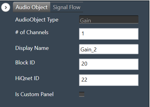
| Display Name | Display the name of the gain audio object in signal flow design. It can be changed based on the intended usage of the object. |
Mode
There are no mode available for Gain audio objects.
Additional Parameters
There are no additional parameters available for the Gain audio object.
Tuning Parameters
The gain audio object supports in-place computation based on the core type.
The following are the paraments you can tune in to GTT.
| Parameter | Description | Unit | Range |
| Gain | Applied on the input channel. | dB | -128 to 20 |
| Invert |
|
None | 0 or 1 |
| Mute |
|
None | 0 or 1 |
Control Interface
There are no control parameters available for Gain audio object.
Delay
The purpose of the Delay audio object is to time shift between the input and output audio samples. The audio object has the ability to add delays to several channels, each with a different delay setting.

However, each channel will support the maximum allowed delay set in SFD. As a result, each channel will have a buffer that is the appropriate size to handle the maximum delay. The Delay audio object can be used when a time delay is required in an audio pipeline. The objects support DelayPool functionality as an operating mode. In this mode, the sum of the individual channel delay configured will be less than or equal to the maximum delay.
Use Case: The Delay audio object can be used when a time delay is required in an audio pipeline.
Delay Object Properties
Below table describes the Delay audio object properties and functionality.
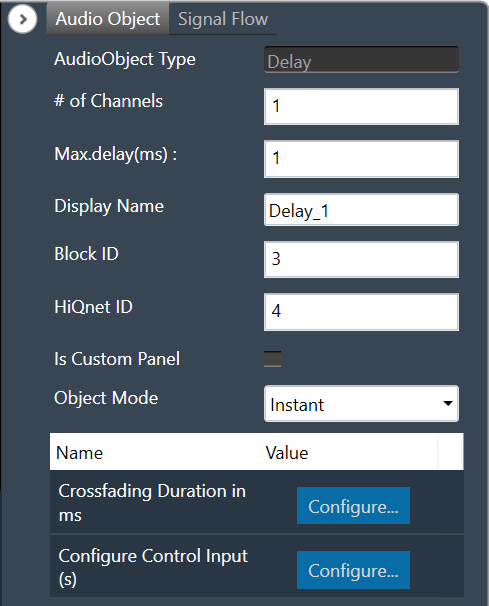
| Properties | Description |
| # of Channels | The number of channels is configurable in the SFD and is always equal to both, the number of input and output channels.
|
| Max.delay(ms) | Specifies the maximum possible delay for each channel in the audio object. For Delay Pool (Refer below on mode details) mode Max Delay is the maximum delay that can be utilized by all channels combined.
Max delay value specified in milliseconds (ms). |
| Display Name | Display the name of the Delay audio object in signal flow design. It can be changed based on the intended usage of the object. |
| Object Mode | Delay object operates in one of the following three modes.
m_Mode is used to specify whether the change in the delay is Instant or uses a Crossfade or operates as DelayPool. |
Mode
Delay object operates in one of the following three modes.
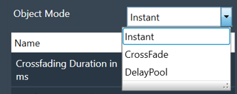
| Parameter | Description | Value | Data Type |
| Instant | No fading – change straight to the newly requested delay value. This is the default mode. | 0 (Instant) | uint |
| CrossFade | To avoid audio discontinuity when the delay value changes. | 1 (Crossfade) | uint |
| DelayPool | Max Delay determines the total DelayPool size which is common for all the channels. When the delay of the individual channel is configured, the sum of delay values (of all the channels) can not exceed Max Delay. Changes in delay values are accepted by the audio object only when the sum does not exceed the Max Delay.
It does not support fading and no control inputs are added in this mode. When the sum of delay values exceeds the Max Delay and preset is applied in parameter sets of GTT, then the UI may group some delay changes into one xTP command. This may cause audio objects to accept some delay value changes and reject other delay value changes. |
2 (DelayPool) | uint |
Additional Parameters
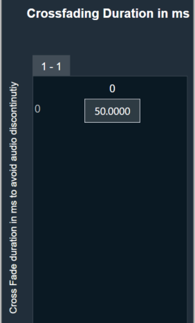
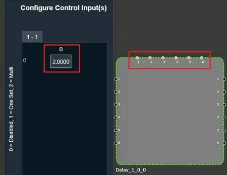
| Parameter | Description | |
| Crossfading Duration in ms | Fade time, only effective when the delay is operating in Crossfade mode.
|
 |
| Configuration Control Input(s) | Configuration control inputs (Enable/Disable).
|
 |
Tuning Parameters
| Parameter | Details | Default Value | Range | Data type |
| Delay | Delay to be applied across each channel | 0 (sec) | 0 – Max.delay (sec) | Float |
Control Interface
| Parameter | Details | Default Value | Range | Data type |
| Delay(OneSet) | One control input is added to set the delay value for all audio channel to the same configured value. | 0 (sec) | 0 – Max.delay (sec) | Float |
| Delay(MultiSet) | One control input per channel is added to set the delay for individual channel. | 0 (sec) | 0 – Max.delay (sec) | Float |
Basic Objects
Basic objects category contains following audio objects.
Control Router
The Control Router audio object provide a mechanism to route control signal from input to output. The router allows to change path of control signal during runtime, which allows for flexibility when designing audio signal pipeline.
This object can be deployed whenever different control inputs to be routed to an object.
It can have arbitrary number of inputs and outputs ranging from 1 to 254 and enables the inputs to be cut or copied to any number of outputs.
Control Router Properties
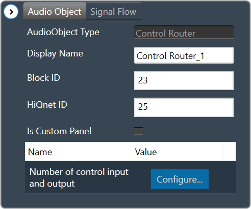
| Properties | Description |
| Display Name | Display name of the Control Router audio object in signal flow design. It can be changed based on the intended usage of the object. |
Mode
There are no mode available for Control Router audio object.
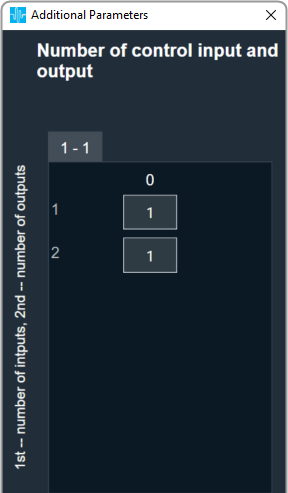
Additional Parameters
| Parameter | Description | |
| Number of control input and output | The max input and output in additional configuration is 100.
Range: 1 to 254 The default number of control input and output pin is 1. |
 |
Tuning Parameters
There are no tuning parameters available for Control Router audio object.
Control Interface
Default control input output is 1 and configurable through additional configuration from 1 to 254 max.
Control Grouper
The Control Grouper audio object allows to merge two or more individual controls and combining them into a single output group, and then send as one signal output group to the connected object.
Use Case: The Control Grouper audio object is useful in context of the Block Control feature. When control signals are received from controlIn AO it will be received as individual control signals. If audio object needs all control signals together then control grouper can be used to combine the control signals.
Refer block control documentation for more details.
Control Grouper Properties
Below table describes about the Control Grouper audio object properties and functionality.
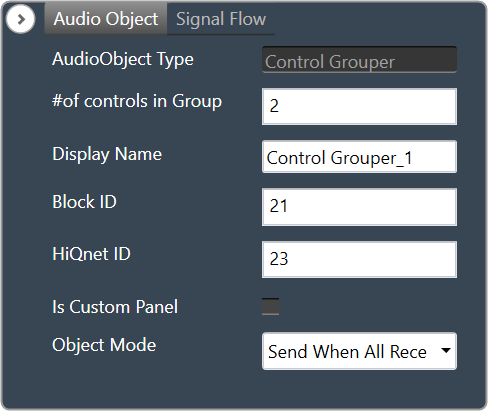
| Properties | Description |
| # of controls in Group | Enter the number of control inputs. It is also the number of signals within the one group to control output.
The number of control group output is always 1.
|
| Display Name | Display name of the Control Grouper audio object in signal flow design. It can be changed based on the intended usage of the object. |
| Object Mode | The audio object supports two modes of operations.
|
Mode
Control Grouper supports two modes.
- Send When All Received (Default mode)
- Send On Apply
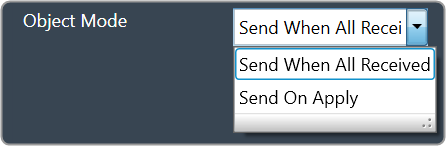
| Mode | Description |
| Send When All Received | In this mode Control Grouper AO does not send a control group output every time a control input is received. The Control Grouper AO waits till all the control inputs are received and then sends the control group output.
If the control inputs are coming at a different rate, the object sends the control group output at the rate of the slowest incoming control input. |
| Send On Apply | In this mode, Control Grouper AO has an additional “Apply” input pin. When input is received on apply pin, Control Grouper AO sends the group output.
Control inputs have default values. These values are exposed as tuning parameters, these values can be modified using state variable explorer. These values are used, when one or more inputs are not received before the input on apply pin is received. |
Additional Parameters
There are no additional parameters available for Control Grouper audio object.
Tuning Parameters
There are no tuning parameters available for Control Grouper audio object.
Control Interface
There are no control parameters available for Control Grouper audio object.
Native Panel
Control Grouper audio object does not support the native panel.
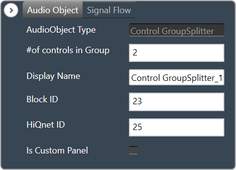
Control GroupSplitter
The Control GroupSplitter audio object splits one control group input into multiple individual control outputs.
Use Case: This object can be deployed if user wants to split the block control to individual control signals which needs to be connected to different audio objects.
Control GrouperSplitter Properties
Below table describes about the Control GroupSplitter audio object properties and functionality.
| Properties | Description |
| # of controls in Group | Enter the number of control outputs. It is also the number of signals within the one group to control input.
The number of control group input is always 1.
The Control GroupSplitter audio object accepts a single block control at its input and splits it into a user-configurable number of single control outputs. |
| Display Name | Display name of the Control GrouperSplitter audio object in signal flow design. It can be changed based on the intended usage of the object. |
Mode
There are no mode available for Control GroupSplitter audio object.
Additional parameters
There are no additional parameters available for Control GroupSplitter audio object.
Tuning Parameters
There are no tuning parameters available for Control GroupSplitter audio object.
Control Interface
The object always has N single control outputs. The number N is described via the number of elements variable in SFD. The object always has one group control input.
Native Panel
Control GroupSplitter audio object does not support native panel.