AudioToControl

The AudioToControl audio object receives audio data, it calculates the envelope based on the mode of operation (either RMS or Peak) and forwards them onto control outputs.
This object accepts N number of input audio signals and calculates the envelope and sends them into corresponding control outputs.

Below are the features of AudioToControl audio object.

  • The control outputs / state values are in linear scale.
  • The AO supports all sample rates and blocklengths supported by xAF. The AO only reads the audio samples for calculating RMS or peak values. The AO supports in-place computation.

AudioToControl Properties

Below table describes about the AudioToControl audio object properties and functionality.

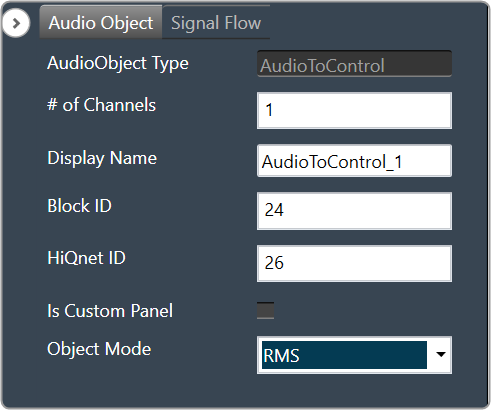
A screenshot of a computer Description automatically generated

Properties Description
# of Channels Enter the number of channels. The number of control outputs are equal to number of channels. This audio object operates in RMS and Peak modes.

  • Range: 1 to 254
  • By default, the number of channels is set to 1.
Display Name Display name of the AudioToControl audio object in signal flow design. It can be changed based on the intended usage of the object.
Object Mode This audio object works in two modes.

  • RMS
  • Peak

Mode

  • RMS: The RMS value of input audio channels are calculated and sent out in corresponding control out channel.
  • Peak: The Peak value of input audio channels are calculated and sent out in corresponding control out channel.

Additional Parameters

There are no additional parameters available for AudioToControl audio object.

Tuning Parameters

It has tunable parameters attack and release time.  Attack and release time are common for all channels.

Parameter  Data Format Memory Offset Unit Range Default Value
Attack time float 0 Msec 0 to 1000 100
Release time Float 4 Msec 0 to 1000 10

The AudioToControl audio object has state parameters envelope value for all channels, rate attack and rate release. The states are read-only.

Parameter  Data Format Memory Offset Unit Range Default Value
Channel 1 envelope Float 0 None – 9999 to 9999 None
Channel 2 envelope Float 4 None – 9999 to 9999 None
Channel N envelope Float (N – 1) * 4 None – 9999 to 9999 None

Control Interface

There are no control inputs. The number of control outputs is always equal to the number of audio inputs.

Native Panel

AudioToControl audio object does not support native panel.

Lookup Table (LUT)

The Lookup Table (LUT) audio object performs a table lookup to create a relationship between a control input and a control output.

For example, The LUT converts vehicle speed value to gain by manipulating the speed values using a look up table. LUT module gives out values of multiple 1-D functions (i.e. control outputs) at specific query points using ‘linear’ or ‘nearest index’ or ‘lower index’ LookUp Method.

The number of columns in the LUT is configurable by modifying the number of control outputs from the SFD. The first column of the table contains one independent vector which corresponds to the x axis of the interpolation. Each of the corresponding columns corresponds to the interpolation slopes for the outputs. The number of rows of LUT denote the number of steps in interpolation of each control output.
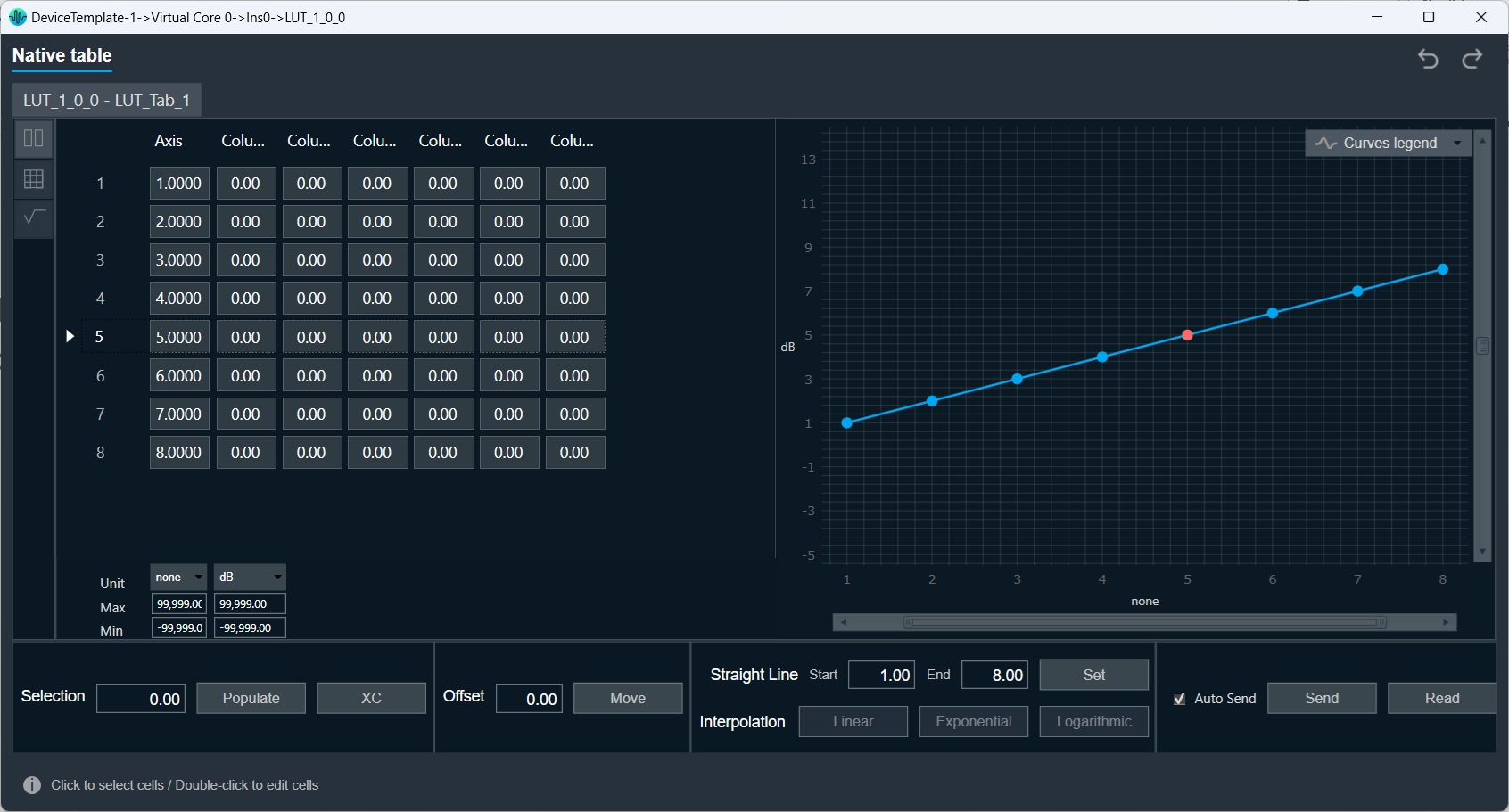
The LUT performs LookUp Method (floor, round, linear interpolation) between values.

  • If the control input is below the minimum value in the x- axis, the LUT will output the minimum value in the table.
  • If the control output is above the maximum value, the output is limited to the maximum value in the table.

The LUT supports Axis Linearity and when enabled, LUT optimizes interpolation and assumes equally spaced steps of interpolation i.e., x-axis interpolation.

  • If ‘Linear Interpolation’ (LookUp Method = 1) is selected and the control input has value between two rows, then it is manipulated to create the control output vector.
  • If ‘Lower Index’ (LookUp Method = 2) is selected and the control input has value between two rows, then control output is the previous known control output which is the (nearest) lower index. This follows for the other control inputs.
  • If ‘Nearest Index’ (LookUp Method = 3) is selected and the control input has value between two rows, then control output is the nearest index (rounded value index). This follows for the other control inputs.

LUT Axis linearity is to be used with linearly spaced axis values.

Every time the LUT receives an input on its control pin, it will output on each control pin output (one per element).

Currently, the LUT is a series of dimensional tables of resolutions from 1-200. The number of elements corresponds to the number of columns. The table resolution on columns is configurable by modifying the first additional variable ‘Table Height’. Both the dependent and independent table values are configurable in the GTT. The x-axis (control-input) needs to be in ascending order and is configurable through the tuning tool.

Lookup Table Properties

Below table describes about the Lookup Table (LUT) audio object properties and functionality.
Properties Description
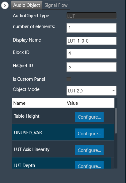
Number of elements Enter the number of channels.

  • Range: 1 to 254
  • Default is set to 1.
Display Name Display name of the LUT audio object in signal flow design. It can be changed based on the intended usage of the object.
Object Mode LUT works in two modes.

  • LUT 2d
  • LUT Index

Mode

LUT audio object is used to manipulate some control input to pass to one or multiple connected objects. The object operates in two modes.

Mode Description
LUT 2d In the 2D mode, there is one control input, and the number of outputs varies based on the number of elements selected.

The objective of this LUT mode is to take in a control input, such as vehicle speed, and interpolate an output value, such as gain, based on values set during tuning. The output is then sent as input to other audio blocks.

Primary Success Scenario

  • The user will tune the object and initialize from GTT.
  • Capture input parameter.
  • Perform interpolation to determine output, based on the selected interpolation type.
  • Output to next object in signal flow.
LUT Index In the Index mode, there is a second control input. This control input selects which ‘set’ of tables to use. Otherwise the modes behave the same. The number of sets is configured by the additional variable ‘LUT Depth’. The maximum depth is 8.

The objective of this mode of LUT operation is to determine output given an indexed set of tables.

  • Primary Success Scenario
  • The user will tune the object and initialize from GTT
  • Capture input parameters
  • Determine which indexed table to use
  • Perform interpolation to determine output, based on the selected interpolation type
  • Output to next object in signal flow

Additional Parameters

Following are additional parameters you can configure, for more details refer to Additional Parameters.

  • Table Height
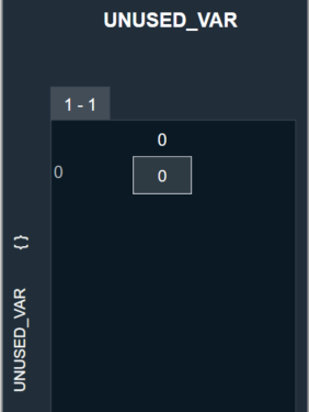
  • UNUSED_VAR
  • LUT Axis Linearity
  • LUT Depth
  • LookUp Method
  • Block Control
  • Group
Parameter Description
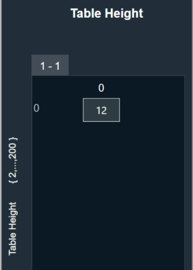
Table Height This parameter corresponds to the size of each table in linear steps which can be configured through an additional configuration variable.

  • Default height of each table in linear steps is 2.
  • Min height of each table in linear steps is 1.
  • Max height of each table in linear steps is 200.
A screenshot of a computer Description automatically generated
UNUSED_VAR This parameter is used to configure old variable through an additional configuration variable which is used to control how values were ramped outside of table ranges. A screenshot of a computer Description automatically generated
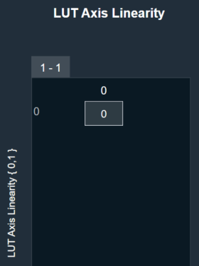
LUT Axis Linearity  This parameter is used to set the manipulation logic for interpolation through an additional configuration variable.

Manipulation logic

  • 0: Input axis may be unevenly spaced. This allows the user to specify table resolution where needed but requires greater effort by the object resulting in slower execution time.
  • 1: Object assumes evenly spaced values on the input axis in order to speed operations.
  • Default value of LUT Axis Linearity is 0.
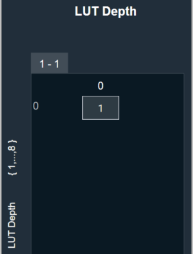
LUT Depth This parameter is used to determine the depth of the table which can be configured through an additional configuration variable.

  • Default depth of each table in linear steps is 1.
  • Min depth of each table in linear steps is 1.
  • Max depth of each table in linear steps is 8.
A screenshot of a computer Description automatically generated
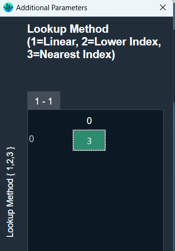
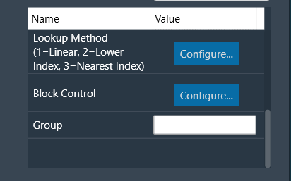
LookUp Method This parameter supports one additional configuration of LookUp Method (linear interpolation/floored index/rounded index) for values on the output axis. This decides how output is computed for an input value that is between two given input axis values.

  • LookUp Method = 1 (Linear interpolation): This is the default type. It provides standard linear interpolation of output between two axis points.
  • LookUp Method = 2 (Lower Index): This is Zero-hold or “previous” type of interpolation. it gives the nearest lower index which is the floor value index. For a given input, control output is the value of the output that corresponds to most previous input.
  • LookUp Method = 3 (Nearest Index): this gives the nearest index which is the rounded value index.
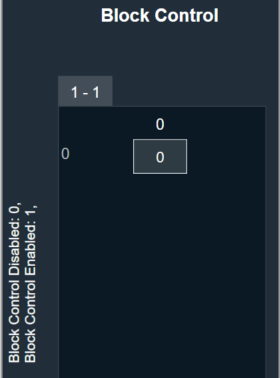
Block Control This parameter supports additional configuration of Block Control which can be enabled or disabled by selecting between Block Control Disabled (default) and Block Control Enabled.

If it is enabled, all the control output signals are grouped into one control pin.

A screenshot of a computer Description automatically generated
Group The Group feature allows organizing the LUT audio objects into different groups. When the native panel of any LUT audio object is opened, all the LUT audio objects with the same group name are displayed in that native panel.

If no LUT objects are assigned to any group, native panel displays all the LUT audio objects.


Tuning Parameters

The total number of tuning parameters depends on the LUT table height, table depth, and number of elements; which specifies the number of dependent output values and is equal to the number of columns in the LUT parameter table.
Hence, the number of elements = number of control outputs = number of LUT table columns.

In the LUT table, there is also an additional column for ‘LUT Index’ mode, which stores the values of x-axis interpolation points. As a result, the total number of elements in the LUT’s parameter memory is as follows.

Parameter Description Data Type Range Unit
m_Params for ‘LUT 2D’ mode Total tuning parameters = (NUM_ELEMENTS+1) * TableHeight Float -99999.0 to 99999.0  None
m_Params for ‘LUT Index’ mode Total tuning parameters = (NUM_ELEMENTS+1) * TableHeight * TableDepth Float -99999.0 to 99999.0 None

Control Interface

There are one or two control input values for LUT based on the mode selected.

  • LUT 2D: 1 float word
  • LUT Index: 2 float words

The first corresponds to the value that needs to be converted to control output. The second determines which table index to use for interpolation.

Name Description Data Type Range Unit
m_states [0] Corresponds to the control input value that needs to be modified. Float -32768.0 to 32767.0  None
m_states [1] Determines which table index to use for interpolation. Float 1.0 to 8.0  None

Create LUT Object

  1. Load xAF DLL in GTT that supports LUT.
  2. Open the Signal Flow Designer.
  3. Drag and drop LUT audio object into the Signal flow design view.
  4. Verify the object is created with no error messages.

The properties and compare to these defaults.

The additional variables below are not actually object variables, they only belong to the GUI object are not covered by this document. See Global Tuning Tool User Guide for further information.

AudioObject Properties Additional Variables
number of elements 1 Table Height 2
Object Mode LUT 2D UNUSED_VAR 0
LUT Axis Linearity 0
LUT Depth 1
LookUp Method 1
Block Control 0

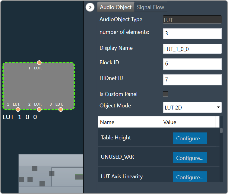
Create LUT Object in Mode 0 (LUT 2D)

  1. The object should already be in mode 0 (LUT 2D).
  2. Verify there is one control input and one control output. Change the number of elements to three.
  3. Verify the object now has three control outputs.
    A screenshot of a computer Description automatically generated

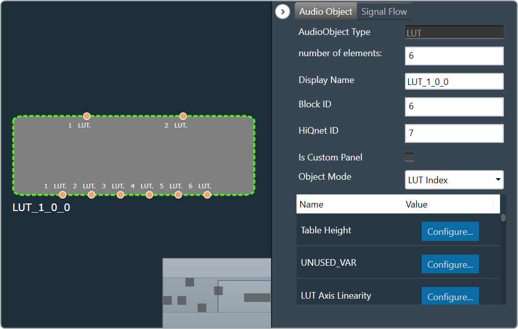
Create LUT Object in Mode 1 (LUT Index)

  1. Change the object mode to LUT Index.
  2. Verify the object now has two control inputs.
  3. Change the number of elements to six.
  4. Verify the object now has six control outputs.
    A screenshot of a computer Description automatically generated

Control Multi Adder

The Control MultiAdder audio object provides the ability to manipulate input control signals. Refer description column of num elements for algorithm description. 

Use Case: This object can be deployed whenever the addition of control inputs is required. Additionally, this object is used as the LUT Adder in Halosonic.

ControlMultiAdder Properties

Below table describes about the Control MultiAdder audio object audio object properties and functionality.
A screenshot of a computer Description automatically generated

Properties Description
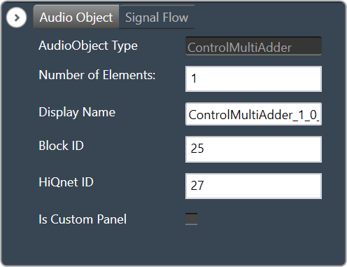
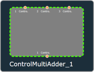
Number of Elements A minimum of three control inputs into the object are summed up and their sum is fed to the control output of the object. Each time the Control Multi Adder control input is set, it calls the corresponding control output. The object has 3 control inputs for elemental addition and forwards control value into an output.

A screenshot of a computer program Description automatically generated

Example: If the numElements is 4, there will be 4 control outputs [y1, y2, y3 and y4] and 12 control inputs [x1 to x12]. The control outputs are computed as shown in the figure below.

Maximum control inputs possible for a control multi adder instance are 255.

For N elements specified from the configuration, 3N control input values would give N control output values. The number of control outputs is selected by numElements.

The number of control inputs = 3 * numElements.

The maximum number of control outputs is limited to 85, So the maximum number of control inputs is 85*3 = 255.

Display Name Display name of the Control MultiAdder audio object in signal flow design. It can be changed based on the intended usage of the object.

Mode

There are no mode available for Control MultiAdder audio object.

Additional parameters

There are no additional parameters available for Control MultiAdder audio object.

Tuning Parameters

There are no tuning parameters available for Control MultiAdder audio object.

Control Interface

There are no control parameters available for Control MultiAdder audio object.

Native Panel

Control MultiAdder audio object does not support native panel.

Control Mixer

The Control Mixer audio object provides a mechanism to mix and route control signal from input to output. The mixer sums values from selected control inputs and pushes the sum to the output. Numbers of inputs and outputs are configurable via GTT. It enables N inputs to be connected to M outputs which is configurable ranging from 1 to 254. If there isn’t any input signal associated with output, the output wouldn’t be changed.

The non-weighted mode with one connected control input output channel. Connection can be changed from state variable window in GTT during tuning, but its impact will be visible once input at that control pins is changed.

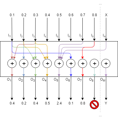
It takes control signals as inputs and emits control signals as outputs. Many inputs can also be connected to one output and output can be left unconnected also. It can copy any input to arbitrary number of outputs (from 0 to number_of_outputs). It means that some inputs can be copied to multiple outputs, or some inputs can be cut (not used further in the pipeline). On the other hand, one output can have at most single input connected to it. Below picture illustrates the idea.

A diagram of a mathematical equation Description automatically generated

Control Mixer Properties

Below table describes about the Control Mixer audio object properties and functionality.

A screenshot of a computer Description automatically generated

Properties Description
Display Name Display name of the control mixer audio object in signal flow design. It can be changed based on the intended usage of the object.
Object Mode Based on the weighing factor of the control inputs to be mixed, the Control Mixer works in two different modes.

  • Non-weight mixer(default)
  • Weight mixer

Mode

The Control Mixer supports in two modes.

  • Non-weight mixer(default)
  • Weight mixer

Additional Parameter

Parameter Description
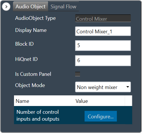
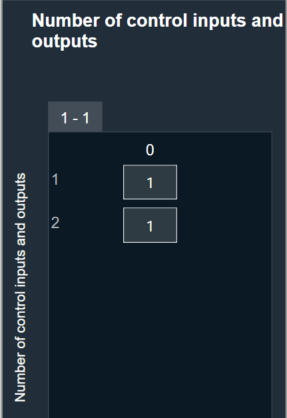
Number of control input and output The max input and output in additional configuration is 100.

Range: 1 to 254

The default number of control input and output pin is 1.

A screenshot of a computer Description automatically generated

Tuning Parameters

There are no tuning parameters available for Control Mixer audio object.

Control Interface

Default control input output is 1 and configurable through additional configuration from 1 to 254 (max).

Control Math

The Control Math audio object provides the ability to manipulate input control signals.

Control Math Properties

Below table describes the Control Math audio object properties and functionality.

Properties Description
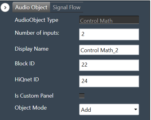
Number of outputs/inputs Enter the number of control outputs or inputs.

  • When the object mode is set to ADD/SUBTRACT/MULTIPLY/MAXIMUM/MINIMUM/EQUAL/ AND/OR/NOR /NAND /XOR the input control pin is enabled.
    • Input value ranges from 2 to 16.
    • The output value is 1.
    • The default value is set to 2.
  • When the object mode is set to LIN2DB / DB2LIN /INVERT / RECIPROCAL / SQUARE / SQUAREROOT the input control pin is equal to the output control pin.
  • When the object mode is set to DIVIDE/GREATER/LESS, the input control pins are 2 and the output control pin is 1.
  • When the object mode is set to NOT/CTRLDELAY, the input and output control pin is 1.
  • When the object mode is set to CTRLSPLIT, the input control pin is 1, and output control pins are configurable between 2 to 32.
  • When the object mode is set to CTRLDUPLICATE, the input control pins are configurable between  1 to 16 and the output control pins are twice the input control pins.
  • When the object mode is set to NONLINEARCLIP, the input control pins are 3, and the output control pin is 1.
  • When the object mode is set to INDEX, the input control pins are configurable between  2 to 255, and the output control pins are 2.
Display Name Display the name of the control math audio object in signal flow design. It can be changed based on the intended usage of the object.
Object Mode Control Math audio object supports twenty-six modes of operation. This audio object can be configured in the SFD to operate in one of the following modes:

  • Add
  • Subtract
  • Divide
  • Multiply
  • Minimum
  • Maximum
  • Lin2dB
  • dB2Lin
  • Invert
  • Square
  • Reciprocal
  • SquareRoot
  • And
  • Or
  • Xor
  • Not
  • Nand
  • Nor
  • Greater
  • Less
  • CtrlSplit
  • CtrlDuplicate
  • CtrlDelay
  • NonLinearClip
  • Equal
  • Index

The default object mode is set to Add.

Mode

The Control Math audio object supports the following modes.

Mode Description
ADD In this mode, control inputs into the object are summed up and their sum is fed to the output of the object.
SUBTRACT The difference between the first control input and the summation of the remaining control inputs into this object is sent out at the output.
MULTIPLY Takes in input controls and writes their product to the output of the object.
DIVIDE Takes 2 input controls and writes the result of their division to the output. If the divisor is zero, the result is set to the maximum float value.
MAXIMUM Takes the input controls and writes out the maximum of the values.
MINIMUM Takes in input controls and writes out the minimum of the values.
LIN2DB Takes a linear control value as an input and outputs its logarithmic equivalent to the specific output pin. If the input is less than or equal to zero, the result is set to zero.
DB2LIN Takes a logarithmic control value as an input and outputs its linear equivalent to the specific output pin.
INVERT Reads in a control value and outputs the negative (inverse) of that value to the specific output pin.
RECIPROCAL Takes in a value, x, and outputs its reciprocal (1/x). If the input value is zero, the result is set to the maximum float value to the specific output pin.
SQUARE Takes in a value, x, and outputs its squared value to the specific output pin.
SQUAREROOT Takes in an input value, x, and outputs its square root. If the input is negative, the result is set to zero to the specific output pin.
AND Takes in multiple inputs and outputs the logical AND operation of these inputs.
OR Takes in multiple inputs and outputs the logical OR operation of these inputs.
XOR Takes in multiple inputs (x1, x2, x3, xn) and outputs the logical XOR operation (((x1 xor x2) xor x3) xor xn) of these inputs.
NOT Takes in an input, and outputs the NOT
NAND Takes in multiple inputs (x1, x2, x3, xn) and outputs the logical NAND operation (((x1 nand x2) nand x3) nand xn) of these inputs.
NOR Takes in multiple inputs (x1, x2, x3, xn) and outputs the logical NOR operation (((x1 nor x2) nor x3) nor xn) of these inputs.
GREATER Takes in 2 inputs, and and outputs true if.
LESS Takes in 2 inputs, and and outputs true if.
EQUAL Takes in multiple inputs and outputs true if all the input values are equal.
SPLITTER Takes in an input control and writes the output to a user-specified number of output pins.
DUPLICATE Takes in a user-specified number of inputs and writes each input out to 2 output pins.
DELAY Takes in a user setting delay (in ms) and writes out the output only after that delay time has passed.
NONLINEARCLIP Takes in 3 inputs, x, min, and max.

  • Provide the output as max if x is greater than max.
  • Provide the output as min if x is less than min.
  • Provide the output as x if x is greater than min and less than max.
INDEX It takes in multiple control inputs and outputs two control values.

  • The first control output returns the index of the minimum value among the control inputs.
  • The second control output returns the index of the maximum value among the control inputs.

In case of maximum or minimum values being the same, it returns the index of the first encounter.

Additional Parameters

The Control Math audio object supports additional configuration which allows to enable or disable Block Control. Which can be enabled or disabled by selecting between Block Control Disabled and Block Control Enabled. The object shall support Block Control in the following operating modes:

Block Control Enabled –

  • Set “Object Mode” to EQUAL / AND / OR / NOR / NAND / XOR to enable the Block control, the number of input control pins can be grouped to one input block control pin.
  • Set “Object Mode” to LIN2DB / DB2LIN /INVERT / RECIPROCAL / SQUARE / SQUAREROOT to enable the Block control, the number of input and output control pins can be grouped to one input block control pin and one output block control pin respectively.

By default, the Block Control function is disabled.

Tuning Parameters

There are no tuning parameters available for the Control Math audio object.

Control Interface

There are no control parameters available for the Control Math audio object.

Native Panel

Control Math audio object does not support the native panel.

Control Generator

The Control Generator audio object allows to generate a constant control value at a specified time.

Control Generator Properties

Below table describes the audio object properties and functionalities.

Properties Description
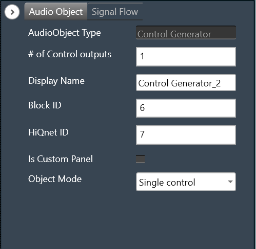
# of  Control outputs Enter the number of control outputs.
In Single control mode, the number of control outputs is configurable between 1 to 255.
In Multi control mode, the number of control outputs is the same as the number of control inputs.

  • Range: 1 to 255 (Min – 1 and Max – 255)
  • By default, the number of output channels is set to 1.
Display Name Display the name of the Control Generator audio object in signal flow design. It can be changed based on the intended usage of the object.
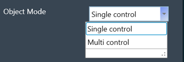
Object Mode This audio object can be configured in two operation modes.

  • Single control
  • Multi control

Mode

The object operates in one of the following two modes:

Mode Description
Single control In this mode, the object has a single control input and configurable control outputs ranging from 1 to 255.
It has a single set of tuning parameters that decide the functioning of all control outputs. Based on the Control value and Trigger time configured, which is applied to all the control outputs,  the constant control value is sent out every “n” seconds i.e. trigger time configured.
If its value is 0 the control value is sent out just once.

This is the default mode.

Multi control This audio object can be configured with control channels ranging from 1 to 255.
The number of control inputs will be equal to the control outputs. The object has a separate set of tuning parameters that decide the functioning of each control output. Control value and Trigger time can be configured separately for each control output.
The default number of control channels shall be 1.

The control input in both modes is triggered only and the value at the control output is set by the Control value tuning parameter.

Additional parameters

There are no additional parameters available for the Control Generator audio object.

Tuning Parameters

The following are the paraments that can be tuned from GTT.

Parameter Description Data Type Range Default Unit
Control Value The value which is sent out to the control output. Setting this value will send the constant control value out. xFloat32 Min: single precision float minimum -3.402823 x 10^38

Max: single precision float maximum 3.402823  x 10^38

0.0f NA
Trigger time It is the rate at which the control value is sent on the control output.

Setting this tuning parameter shall send the constant control value out. If its value is 0 the control value is sent out just once. If its value is greater than 0, let’s say a value of N, the control value shall be sent out every N seconds.

xFloat32 0 – 600 0.0f seconds

Control Interface

The Single-control mode has a single control input and configurable control outputs. The control outputs are configured using the “# of Control outputs” property.  The control output value ranges from 1 to 255.

By default, control input and control output is 1.

The Multi-control mode has configurable control outputs. The control outputs are configured using the “# of Control outputs” property.  The control output value ranges from 1 to 255.
The number of control inputs is equal to the control outputs.

Native Panel

The Control Generator audio object does not support a native panel.