Fader Balance Panel

Basically, this audio object allows to identify the “sweet spot” of the sound by moving in the x and y directions. Using this method, you can optimize the sound loudness on the left or back of the cabin.
Used to map the channels to Balance Speaker group and Fader speaker group.

A screenshot of a computer Description automatically generated

  • Morphing time: The range is from 0 s (no morphing) to 0.1 s.
    Morphing time follows time constant and the morphing time is denoted as M. Following is the percentage of change achieved:
    – After M: 63%
    – After 2M: 86%
    – After 3M: 95%
    – After 4M: 98%
    – After 5M: 99%
    Hence the morphing time can be configured accordingly.

The morphing time (through V release) is actually a time constant.  Therefore if you want your morph 99+% complete in 100ms you should specify 20ms, not 100.  One time constant will morph 63% of the way there.

  • Channel assignment: Assigns a particular audio channel to one or none of the speaker types in each group.
    • Balance Speaker Types: CENTER, LEFT & RIGHT
    • Fader Speaker Types: CENTER, SIDE, BASS, FRONT & REAR

Fader tab

Used to control the gain level of fader in the range -128  to 0 dB.

  • Front
  • Center
  • Side
  • Rear
  • Bass

Balance tab

Used to control the gain level of balance in range -128 dB to 0 dB.

  • Center
  • Left
  • Right

Volume and Mute Panel

When engineers need to control the volume or mute settings in their audio pipeline, they utilize the Volume and Mute audio objects. To modify the parameters of these objects, a custom native panel is used.

Possible configuration and its effects are shown in the table below.

Configuration Effect
Mode Tune and State Ramp Characteristic
OneSet Volume , Mute, and Invert is common to all channels.

Ramping values is common to all channels.

MultiSet Volume ,Mute and Invert is for each individual channels.

Ramping values is common to all channels.

MultiSet Ramp Volume, Mute, and Invert and Ramping values is for each individual channels.

Based on the configuration, user interface of the panel can vary.

As a result of this fact, the user interface of the current panel also undergoes changes to accommodate all the controls necessary for handling the audio object configuration.

 You can modify any available state variables.

  • To change volume, down or up ramp rate/time please use vertical faders or textboxes under them.
  • To mute a specific channel in “Multi Set” modes or all channels in “Single Set” mode, simply click on the “Muted” or “Unmuted” button.
  • To shift the phase of a specific channel in “Multi Set” modes or all channels in “Single Set” mode, click on the “In Phase or Inverted” button.

For ramping parameters, ramp shape can be set in one out of three shapes.

  • Linear ramp shape
  • Exponential ramp shape
  • Jump ramp shape (volume increases immediately without any ramp shape)

Matrix Mixer Panel

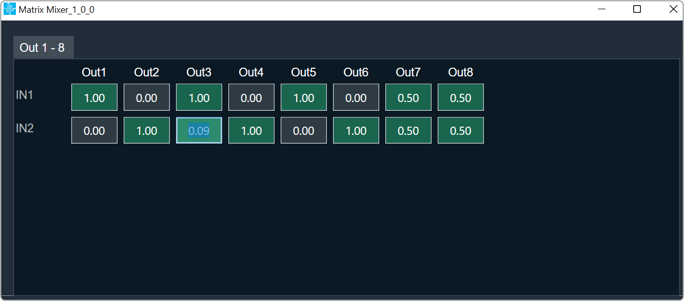
The Matrix Mixer native panel allows you to mix ‘n’ number of channels to ‘m’ output channels.

There is no native panel is for DelayMatrixMixer.

The panel can be launched in two modes:

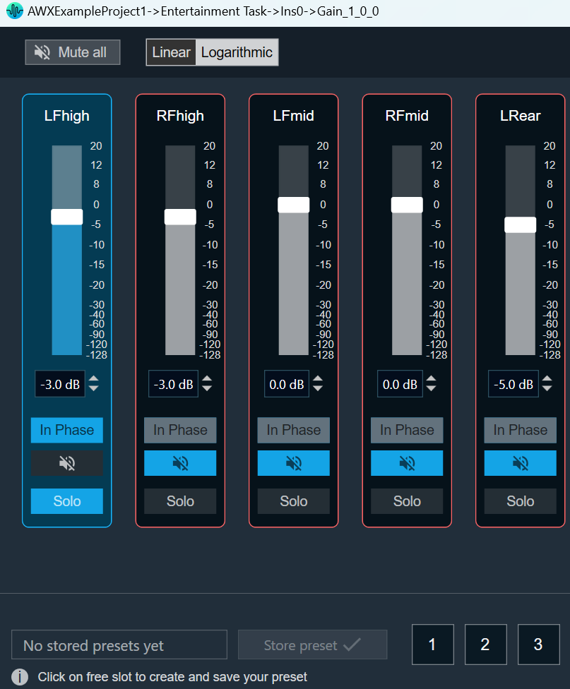
  • Linear: For linear mode it is possible to set gain with two decimal points precision.
  • dB: For dB mode precision is set to 1 decimal point.

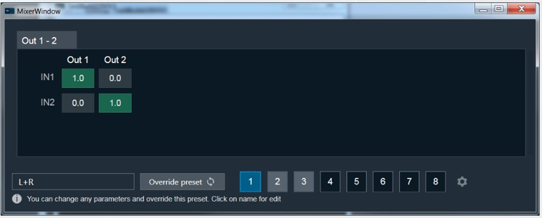
In the example below, there are two input channels and two output channels.

Example 1: “IN1” is sent to channel one and “IN2” is sent to channel two.

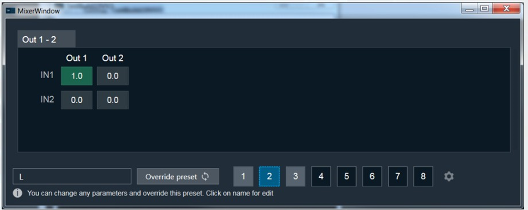
Example 2: “IN1” is sent to channel one and “IN2” is muted.

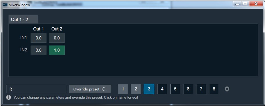
Example 3: “IN1” is muted and “IN2” is sent to channel two.

A screenshot of a computer Description automatically generated

Set Linear Gain

When you click on a cell, you can change the gain value using the keyboard.
To set the value to zero or one, press CTRL and use the mouse scroll to adjust the value, or simply enter the values.

A screenshot of a computer Description automatically generated with medium confidence

Cell Selection Methods

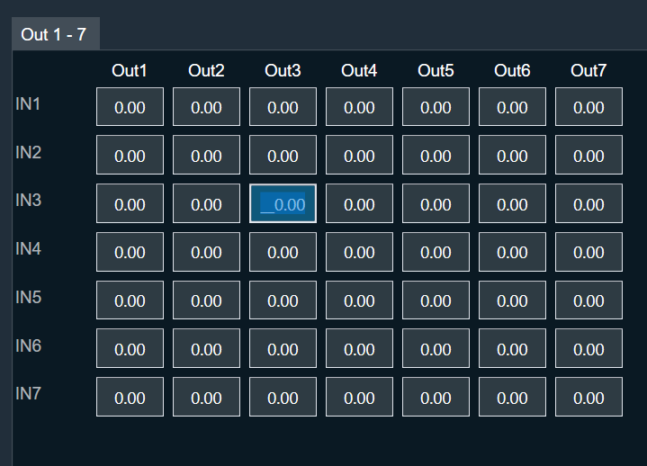
Single cell selection method: You can select a single cell with the mouse by using the left click or the tab key on the keyboard. The selected cell will be highlighted as you can see in the example below. The text inside the selected cell is editable.

Multiple cell selection methods: There are two ways to select multiple cell.

  1. Method 1: By clicking and dragging with the mouse. This method is useful when you are selecting small range of cells.
  2. Method 2: By using keys on the keyboard. This method is useful when rendered outside of the view area when the grid scrolls either vertically or horizontally.

Method 1: To select multiple cells using mouse, follow the below steps.

  1. Place the cursor on cell.
  2. Select the cell by using the left mouse button and keep the mouse button pressed.
  3. Drag the cursor in the respective cell. Automatically the cells will selected in matrix form.
  4. Leave the mouse button.

The selected cell will be highlighted as you can see in the example below.

Method 2: To select multiple cells that is rendered outside of the view area when the grid scrolls either vertically or horizontally, you can use below method for selecting multiple cells.

If you want select a cell that is rendered outside of the view area when the grid scrolls either vertically or horizontally, you can use below method for selecting multiple cells.

  1. Click on a first cell of the range.
  2. Use scroll to navigate to last cell of the range.
  3. Hold Shift key and click on the last cell of the range. This will automatically select every cell in the matrix form.

The selected cell will be highlighted as you can see in the example below.

Selecting arbitrary cells is not allowed. Selection is always in the form of matrix.

A single tab displays the 12×12 matrix (INs and OUTs) in the matrix mixer. In the event that there are more AudioIn or AudioOut, it will be split up into multiple Tabs. The chosen region is reset and is not tracked when the tab is changed, as shown below.

Copy and Paste Functionality

You can copy and paste matrix mixer table data into Excel or vice versa. There are several methods for copying and pasting data.

Method 1: To copy panel cell data to Excel.

  1. Place the cursor on cell, select the cell by using the left mouse button and keep the mouse button pressed.
  2. Drag the cursor in the respective cell. Automatically the cells will selected in matrix form.
  3. Press Ctrl + C on your keyboard. The content gets copied to clipboard.
  4. Switch to Excel spreadsheet.
  5. Press Ctrl + V on your keyboard in the desired location within your Excel spreadsheet.

For seamless data exchange, the copied content uses a standard tab-delimited matrix format (‘t’). This preserves the exact layout and allows easy import into various applications. This format is a standard across various applications.

Method 2: To copy data from Excel to matrix mixer table.

To paste content from Excel to Matrix Mixer first copy excel content to clipboard via keyboard Ctrl + C and on matrix mixer table select single cell from where content begin paste and use Ctrl + V to paste as shown below.

  1. In your Excel spreadsheet, use cursor on cell to select the respective cell from the Excel.
  2. Press Ctrl + C on your keyboard. This copies the data from the selected cells.
  3. Switch to Matrix Mixer table.
  4. Choose the cell and press Ctrl + V.

When you paste data, the affected cells will be highlighted. However, only the cell in the bottom right corner of the pasted region becomes active. This means you can only directly edit this cell with mouse or keyboard input.

Efficient pasting for repetitive data: For situations where you need to paste the same content in multiple locations, Matrix Mixer table offers a convenient repeat paste function.

  1. In your Excel spreadsheet, use cursor on cell to select the respective cell from the Excel.
  2. Press Ctrl + C on your keyboard. This copies the data from the selected cells.
  3. Switch to Matrix Mixer table.
  4. Choose the cell region larger than selection and press Ctrl + V once.

In this example, a 2×2 matrix is effectively replicated into a 4×4 area.

The copied matrix dimensions must be an exact multiple of the selected region for repeat pasting functionality. If this condition is not met, the content will be pasted only once starting from the active cell.

Efficient data copy within Matrix Mixer: Utilize keyboard shortcuts for quick and easy data movement. Select the cells you want to copy, press Ctrl + C to copy them. Next, choose the cell where you want to paste the copied data and press Ctrl + V. As shown below, this allows you to seamlessly copy information within the Matrix Mixer table.

Cross-panel data transfer: The copy and paste functionality in Matrix Mixer (Ctrl + C and Ctrl + V) offers flexibility beyond the panel. It enables you to efficiently move data between Matrix Mixer tabs and other applications that utilize a grid-based control, like the LUT Panel. This is achievable because copied content is stored on the clipboard, allowing access across the application and your operating system.

Copy and Paste Validation

Data exceeds paste area: When you try to paste content that’s larger than the selected region, you’ll see an “Out of Region” message. This means there’s not enough space to paste everything. You’ll have two options:

  • Cancel: Choose this to avoid pasting any data and prevent accidental loss.
  • OK: Click this to paste as much of the content as possible within the selected area. Some data might be cut off.

Tip: To ensure a complete paste, make sure the copied data is the same size or smaller than the area you’ve selected in Matrix Mixer.

Pasting incompatible data: If you try to paste content that contains non-numeric values (like text or symbols) into Matrix Mixer table, you’ll see an “Invalid Data” message. This means the data format isn’t compatible. You’ll have two options:

  • Cancel: Choose this to avoid pasting any data and prevent errors.
  • OK: Click this to paste only the valid numeric values from the copied content. Any invalid data will be ignored.

Tip: Make sure the copied data only contains numbers before pasting into Matrix Mixer.

Data values outside limits: When you try to paste content that contains values exceeding the allowed range for the selected cell(s), you’ll see an “Out of Range” message. Matrix Mixer has specific value limitations (e.g. 0-10). This means some of the data might be invalid. You’ll have two options:

  • Cancel: Choose this to avoid pasting any data and prevent errors.
  • OK: Click this to paste only the valid values within the allowed range for each cell. Any values outside the range will be ignored.

Tip: Before pasting, ensure the copied data adheres to the valid value range of the cells in your selected region.

Copying data with uneven columns: Matrix Mixer table allows you to paste data with variable columns, unlike Excel which requires a strict matrix format. This is helpful for situations where data from sources like Notepad might have missing values or uneven columns.

Example: As shown below, you can copy a 3×2 matrix from Notepad, where some columns might have empty cells. Matrix Mixer will interpret the data based on its structure and paste it accordingly.

Tip: While Matrix Mixer can handle variable dimensions, ensure the overall structure of the copied data remains consistent  with the standard format i.e values separated by tab delimiter (‘t’).

Preserving existing data: Matrix Mixer table allows you to selectively paste content while keeping your existing data intact. To achieve this, copy data from Excel with blank cells where you want to skip pasting. You might see an “Invalid Data” message because empty cells are considered invalid. However, clicking “OK” will continue the paste, leaving your existing values in those blank cells untouched.

Matrix Mixer table displays validation error messages only once, even if there are multiple invalid cells in the pasted data. Clicking “OK” will attempt to paste all valid data into the corresponding cells, while skipping any invalid values without affecting existing content.

Limiter Panel

The Limiter Panel is used for changing the gain, threshold, hold threshold, attack time, hold time, and release time values for each channel.

The Limiter panel displays the current attenuation value for information purpose only. Attenuation is a state-type parameter. This means the attenuation value is coming from the device and cannot be modified within the Limiter panel. To get the current attenuation value,  you need to stream the attenuation state variable.


There is a tooltip for Attack Time that describes its behavior as shown below.

A screenshot of a computer Description automatically generated with medium confidence

Similarly, tooltip is available for Release Time for its behavior as show below.

A screenshot of a computer Description automatically generated with medium confidence

Changing Value

You can change the gain value in four ways:

  • Using slider button: Select the slider to adjust the value.
  • Using mouse scroll: Click on the respective column and use mouse scroll to adjust the value.
  • Using text box: Select the respective column and enter the dB value within the specified minimum and maximum range. Once you’ve entered the value, press Enter, and the slider will automatically adjust based on the input.
  • Using the increment and decrement buttons you can change the gain value.

Maximum / Minimum Gain Value

Maximum and minimum gain values are from corresponding state variable of Limiter.

Threshold Values

Maximum and minimum threshold values are derived from the GTT in the parameter store.

When either of the threshold values is reached, the Gain value bar will turn into red.

  • Maximum threshold value: 95 %
  • Minimum threshold value: Not set

For further info on the Limiter audio object and its functional behavior, please also refer to the Limiter User Guide Supplement.

Tone Control Extended

The ToneControlExtended audio object supports changing the filter parameters Frequency, Gain, Q, type of the filter and ramp time for each channel in Signal Flow Designer.

The tone control extended block can generate filters and their coefficients and then filtering audio signals passed to the audio block based on the calculated coefficients. The tone control extended object can have a variable number of channels and have one set of filter coefficients per element for all channels. It has an adjustable number of elements or cascaded filters.

Use Case: This audio object applies filter on all the channels. When filter parameters are changed during run time, the filter coefficients are gradually changed to target values using ramping. Linear interpolation is used for filter ramping. Filter coefficients are ramped after every pre-configured number of samples for ramping. This ramping is applied until filter coefficient reaches target value.

ToneControl Properties

Below table describes about the ToneControlExtended audio object properties and functionality.

Properties Description
# of Channels Enter number of channels. The number of input channels is always equal to the number of output channels.

  • Range: 1 to 32
  • Data Type: uint32_t
  • Default: 1
Number of bands Enter number of bands per channel.

  • Range: 1 to 16
  • Data Type: uint32_t
  • Default: 1
Display Name Display the name of the ToneControlExtended audio object in signal flow design. It can be changed based on the intended usage of the object.

Mode

There are no mode available for ToneControlExtended audio object .

Additional Parameters

Parameters Description
Biquad Topology It supports one additional configuration of Biquad topology which can be selected among the available topologies.

  • 0 = DF I
  • 1 = DF II
  • 2 = DF II Transpose

By default, it is configured for DFI.

Block Control It supports additional configuration of Block Control which can be enabled or disabled by selecting between Block Control Disabled and Block Control Enabled.

0 = Block Control Disabled

1 = Block Control Enabled

If it is enabled, Frequency, Quality and Gain control signals of each band are grouped into one control pin and need to be set as a tuple. This means that the AO setting those needs to make sure all the three values are available.

By default, it is configured for Block Control Disabled.

Tuning Parameters

For each filter in the tone control, this object exposes these five tuning parameters to the GTT.

There are no control output and three control inputs per filter element. Using control inputs user can change cut off frequency, Gain and Quality factor.

Parameter Description Tunable or Controllable Unit Range Default
Frequency Filtering frequency to be applied

Tuning

Control

Control/Tunable Hz 10 Hz – 20 kHz 20 Hz
Gain Filter gain

Tuning

Control

Control/Tunable dB -30 to + 50 dB 0 dB
Quality Quality of the filtering coefficients

Tuning

Control

Control/Tunable  None 0.1 – 10 0.71
Type Filter type Tuneable  None
  • Bypass
  • Allpass order 1
  • Allpass order 2
  • Highpass order 1
  • Highpass order 2
  • Lowpass order 1
  • Lowpass order 2
  • Highshelv order 1
  • Highshelv order 2
  • Lowshelv order 1
  • Lowshelv order 2
  • Peaking (EQ)
  • Bandpass
  • Bandstop
  • Amplifier
  • Reson
AllPass
RampTime Ramp time for filter coefficient to adapt to new coefficient Tunable msec 0 to 500 msec 10.0 msec

Control Interface

There are no control parameters available for ToneControlExtended audio object .

FastConv

This FastConv (Fast Convolution) audio object implements an N-channel point to point FIR filter with a constant number of taps for all channels. This filter is optimal for higher order filters (> 1000).

Coefficients are provided through GTT custom panel from pre-stored coefficient files in .csv format.

  • Coefficients can be different for each channel, but with same tap length.
  • Coefficients represent the impulse response of the filter in time domain.

Without loaded coefficients, the filter functions as an all-pass filter passing the input signal as it is.

The FastConv audio object supports in-place computation based on the core type.

Use Case: The computational effort of a simple FIR filter in time domain increases linearly with the number of taps used.
For complex wideband filtering, example low frequency filtering using room impulse responses – the number of used taps might easily reach few hundreds or thousands. As this number of FIR taps in time domain cannot be realized with reasonable computational effort, it makes sense to do convolution by multiplication in frequency domain – using the FFT.
The trade-off for using fast convolution depends on the used platform and might be in the area of 32-64 taps.
As this filter supports multiple channels – it can be used to adjust the sound to certain acoustics in a multichannel environment. The impulse response, i.e. the time domain coefficients can be different for each channel.

FastConv Properties

Below table describes about the FastConv audio object properties and functionality.

Properties Description
# of Channels The object has a configurable number of channels. The number of audio inputs is always equal to the number of audio outputs.

  • Range: 1 to 255
  • By default, the number of channels is set to 1.
Number of taps The object has a configurable number of taps.

  • Range: 1 to 16384
  • By default, the number of channels is set to 1.
Display Name Display the name of the FastConv audio object in signal flow design. It can be changed based on the intended usage of the object.

Mode

There are no mode available for FastConv audio object.

Additional Parameters

There are no additional parameters available for FastConv audio object..

Tuning Parameters

In the current init setup, the tuning filter coefficients consist of all pass or bypass. In the real-world setup, these will be replaced with actual filter coefficients calculated for the preferred vehicle environment.

There are two sets of tuneable parameters –

  • Mode: Mode is a single variable
  • Coefficients: the number of coefficients depends on the tap-length value configured in GTT

Let Nc denote the number of coefficients (taps), Ni number of channels. All filter coefficients are stored using floating point format. The number of coefficients is rounded up to an integer power of 2, which allows for effective FFT radix-2 or radix-4 implementation. The filter coefficients are denoted by hi[k] where “I” is the filter’s index ranging from 0 to Ni−1 and “k” is the coefficient index (k = 0…Nc−1).

Sub-block ID Name Description Offset Type Unit Range Default
0 mode [0] Mode for filter 0 0 UInt32 None 0,1,2 0
0 Coefficients for filter 0 4 float None -1.0f; +1.0f 1.0f
0 Coefficients for filter 0 8 float None -1.0f; +1.0f 0.0f
0 Coefficients for filter 0 float None -1.0f; +1.0f 0.0f
0 Coefficients for filter 0 + 4 float None -1.0f; +1.0f 0.0f
1 mode [1] Mode for filter 1 + 4 UInt32 None 0,1,2 0
1 Coefficients for filter 1 + 8 float None -1.0f; +1.0f 1.0f
1 Coefficients for filter 1 + 8 float None -1.0f; +1.0f 0.0f
1 Coefficients for filter 1 float None -1.0f; +1.0f 0.0f
1 Coefficients for filter 1 + 12 float None -1.0f; +1.0f 0.0f
Ni-1 mode [Ni-1] Mode for filter Ni-1 + UInt32 None 0,1,2 0
Ni-1 Coefficients for filter + float None -1.0f; +1.0f 1.0f
Ni-1 Coefficients for filter float None -1.0f; +1.0f 0.0f
Ni-1 Coefficients for filter + float None -1.0f; +1.0f 0.0f

The pre-computed FIR filter time domain coefficients need to be stored in a file in .csv format.

GTT has the provision to import the coefficients from the file for the selected channel and pass them to the device. During tuning phase, these time domain filter coefficients are converted to frequency spectrum coefficients for multiplication with the spectrum of the input.

The generalized offset information of the two tuneable parameters can be found below table.

FastConv Tuneable Parameters

Sub-block ID Name Description Offset Type Unit Range Default
i mode[i] Mode for filter i UInt32 0,1,2 0
i Coefficient k=0 for filter i float -1.0f; +1.0f 1.0f
i Coefficient k>0 for filter i float -1.0f; +1.0f 0.0f

FastConv operational mode (Normal / Bypass / Mute) can be controlled (as tuning parameters) from GTT panel. The description of each mode is given in the table below.

FastConv Mode Details

Mode Value Mode Tag Description
0 NORMAL Filter operation under use
1 BYPASS Input buffer copied to output buffer
2 OFF Output buffer set to zero

Control Interface

There are no control parameters available for FastConv audio object.

FIR Filter

The FIR Filter audio object implements a mechanism for time domain FIR filtering. FIR filters are more stable than IIR filters and can be designed to have linear phase response. However, they require a filter of higher order for similar response as an IIR and hence computationally intensive.

The filter operational mode can be controlled from GTT. The FIR filter coefficients can be provided through GTT custom panel from pre-stored coefficient files in .csv format.

Use Case: FIR filters are mostly used in applications that require linear phase. They are inherently more stable than IIR filters. However, FIR filters are generally computationally intensive. The applications include:

  • Correction of frequency response errors in a loudspeaker.
  • Phase correction in communication lines.
  • Parametric and crossover filters implemented with FIRs can be implemented with or without phase shift.

FIR Filter Properties

Below table describes about the FIR Filter audio object properties and functionality.

A screenshot of a computer Description automatically generated

Properties Description
# of Channels The FIR Filter audio object has a number of input channels that is double the number of output audio channels.

  • Range: 1 to 255
  • Default: 2
Number of taps for filter Specify the number of elements which is the order of filter.

  • Range: 2 to 1024
  • Default: 2
Display Name Display the name of the FIR Filter audio object in signal flow design. It can be changed based on the intended usage of the object.

Mode

Mode Description
Normal The FIR Audio Object shall perform the normal filter operation individually for each channel with the set of coefficients provided for each channel. The filter type can vary for each channel but the number of coefficients of all channels need to be the same.
Bypass The FIR Audio Object shall copy the input signal to the output buffer bypassing the filter operations. Each channel can be selectively bypassed.
Off The FIR Audio Object clears the output buffers.

Additional Parameters

There are no additional parameters available for FIR Filter audio object.

Tuning Parameters

There are two sets of tunable parameters – mode and coefficients.

  • Mode is a single variable.
  • The number of coefficients depends on the tap-length value configured in GTT.

Let Nc denote the number of coefficients (taps), Ni number of channels. All filter coefficients are stored using floating point format. The filter coefficients are denoted by hi[k] where “i” is the filter’s index ranging from 0 to Ni−1 and “k” is the coefficient index (k = 0…Nc−1).

The generalized offset information of the two tunable parameters can be found below table.

 FIR Tunable Parameters Offset

Name Description Offset Type Unit Range
mode[i] Mode for filter i UInt32
  • 0 – Normal
  • 1 – Bypass
  • 2 – Off
Coefficient k for filter i float -1.0f; +1.0f

FIR Tuneable Parameters Default Values

Name Description Default Values
Mode Operational Mode 0 – Normal
FIR Coefficients FIR Coefficient Array input [1.0f, 0.0f, 0.0f, ……… 0.0f] – All pass

Control Interface

There are no control parameters available for FIR Filter audio object.

Gain Panel

The Gain panel associated with Gain audio object. The Gain panel is used for changing the gain of a signal for each channel.

When you open a gain native panel, the Logarithmic scale is set to the default value. You can toggle option to switch between Linear and Logarithmic scale.

The gain values in the Logarithmic scale are rounded off to nearest next digit. For Linear scale values are retained as user entered.

  • Logarithmic Scale: Gain values are displayed rounded to the nearest whole number.
    Example:
    If the gain value is -10.4 in Logarithmic scale it will be shown as -10.
    If the gain value is -10.7 in Logarithmic scale it will be shown as -11.

All Gain panel functionalities are fully supported and work seamlessly when using the logarithmic scale.

  • Linear Scale: Gain values are shown exactly as entered.
    Example:
    If the gain value is -10.8 in Linear scale it will be shown as -10.8.

On switching between these two options only scale is changed, State variable values and Tunning data remain same, Unless user changes the actual value.

When switching between logarithmic and linear scales, only the way gain values are displayed is affected. The underlying state variable values and tuning data remain unchanged unless you manually change the actual value.

  • Maximum / Minimum Gain Value:  The maximum and minimum gain values are from corresponding state variable of Gain.
    • Maximum value: 20 dB
    • Minimum value: – 120 dB
  • Threshold Values: The maximum and minimum threshold values are derived from the ParameterStore in GTT. Once either of the threshold values is reached, the Gain value bar will change to the color red.

  • In Phase / Invert: To invert or Inphase the gain value
    • Click on the In Phase to invert the gain value.
    • Click on the Inverted to in phase the gain value.
      A screenshot of a computer Description automatically generated with low confidence
  • Mute: The Mute button sets the gain value to a minimum gain value. Even if the gain value is muted, you can change it. 
    A screenshot of a computer Description automatically generated with low confidence
  • Mute all: The Mute all button sets all gain values to minimum gain values. If all gains are muted, the Mute all button will change to Muted. 
    A screenshot of a computer Description automatically generated with medium confidence
  • Solo:  The Solo button mutes all the channel except the selected one. Additionally, the phase of all the muted channels get disabled. Click on the Solo button again, to unmute all the channels.

To change the Gain value

You can change the gain value in four ways:

  • Using slider button: Select the slider to adjust the value.
  • Using mouse scroll: Hover on the respective column and use mouse scroll to adjust the value.
  • Using text box: Select the respective column and enter the dB value within the specified minimum and maximum range. Once you’ve entered the value, press Enter, and the slider will automatically adjust based on the input.
  • Using the increment and decrement buttons  you can change the gain value.