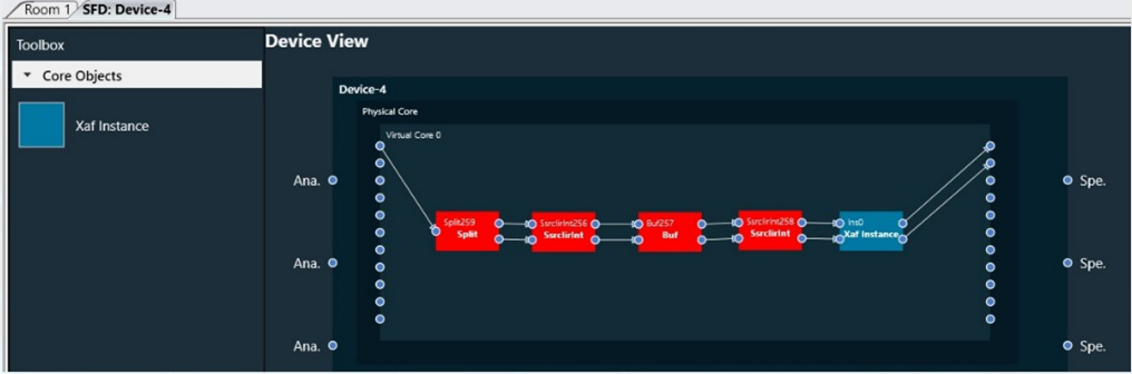
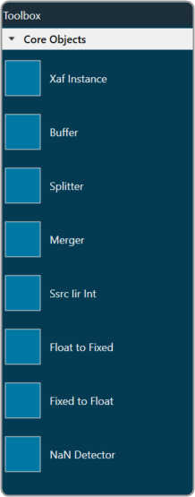
The Toolbox contains the core objects that were retrieved from the xAF dll. The objects that can be used within the core to create the device signal flow are called core objects. Each core object has its own purpose and solves parametric issues which block routing within the core.
Core Objects are classes that are part of the Audio Core (virtual core) class and operate at a higher level than audio objects. The audio processing class itself is a core object. The relationship between core objects and Audio core is similar to that of audio objects and the Audio Processing class.
The execution order (or index) of the core object is displayed by Core Object Id. Routing determines the order in which core objects are executed within a core. The core objects that are connected to the core input will be executed first, and the core objects that are connected to the root object after that will be given the next execution order.
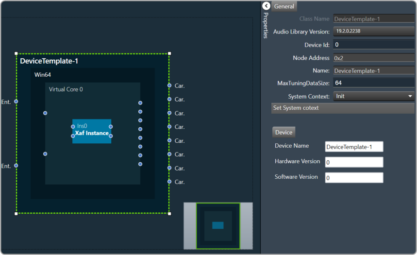
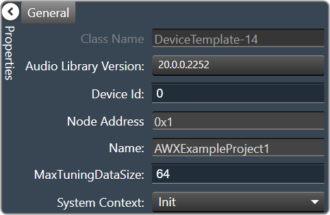
The device identification feature is enabled for audio libraries version 13 and higher.
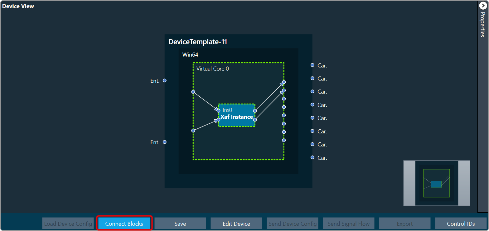
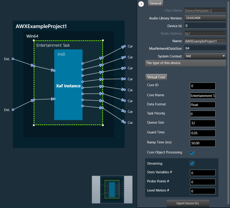
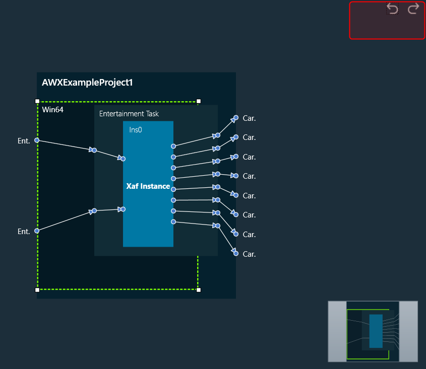
Xaf Instance
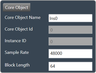
The Xaf Instance is the core object inside which the signal flow for that instance can be created.

- Core Object Id (execution order of core-object with-in core) and Instance Id (index of xAF instance with-in core, based on execution order) will be displayed as read-only fields.
- The sample rate and block length of the instance will control signal flow within the instance. You can change the sample rate and block length of the instance in the properties section.
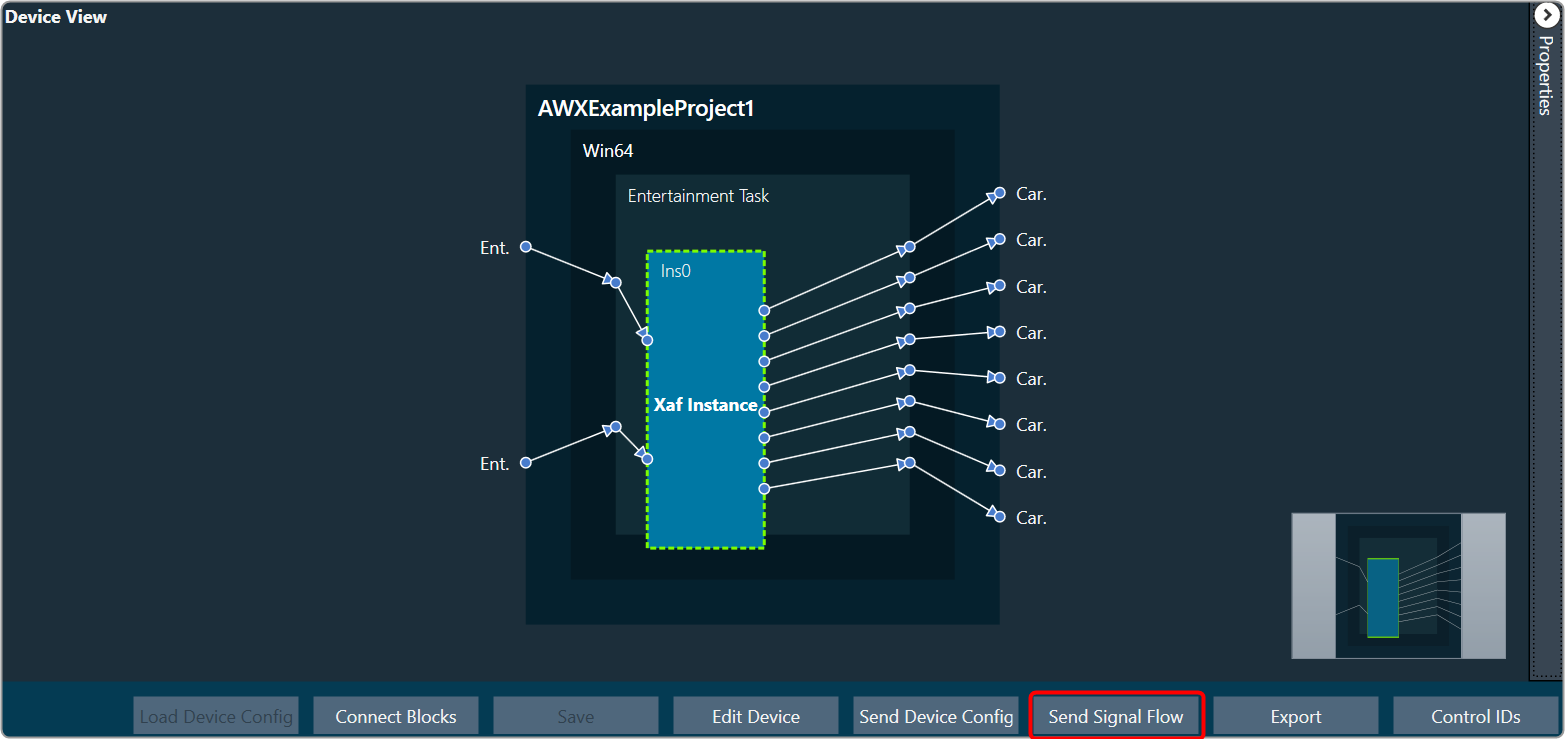
Further information on signal flow creation is available in the GTT Signal Flow Designer guide.
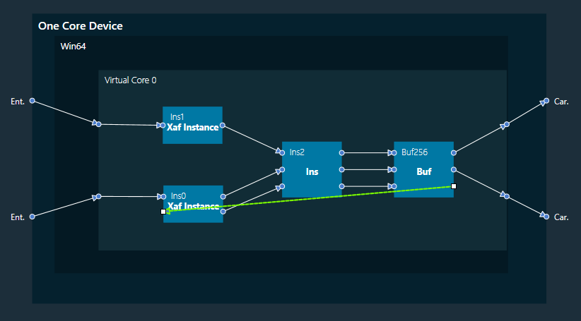
Buffer
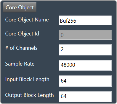
Buffer core object is used to convert the input block length into the required output block length. The buffer core object has an equal number of input and output channels. It can be used as a pass through core object OR it can be used to, as its name suggests, buffer samples from the input to the output. The object does not change the sample rate (it is the same at the input and the output).

If you want to connect two core objects with different block lengths, you can use a buffer core object. As a result, the input block length will be the Block Length of the first core object, and the output block length should be the Block Length of the other core object.
It can be configured as follows:
- If the input block length is equal to the output block length, then it behaves as a pass through object (so you could have an audio core with a buffer object to connect the core input to the output)
- Input and output block lengths must be integer multiple of each other
- When input and output block lengths are not equal, the object handles taking in input at a lower block length and outputting it at a higher one and vice versa. For example, it facilitates the connection of an object at block length 32 to an object at block length 64
Introducing this object into your signal flow for any case but pass through WILL result in latency at the output.
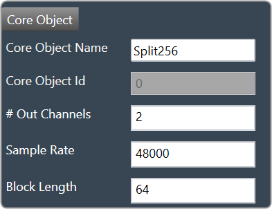
Splitter
Splitter core object is used to convert one input to multiple outputs of the same sample rate and block length.

- This core object always has a single input.
- In order to make routing from any core object to the splitter both the source core object and splitter core objects sample rate and block length should match.
- Number of output channels for the splitter is configurable.
It is not to be confused with the Splitter audio object.
This object operates in parallel to an xAF instance NOT within it.
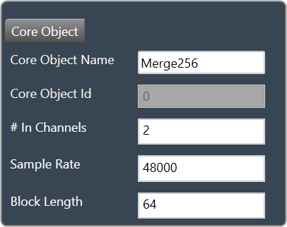
Merger
Merger core object is used to merge multiple inputs into a single output of the same block length and sample rate.

- This core object always has a single output.
- In order to make routing from any core object to merger both the source core object and merger core objects sample rate and block length should match.
- Number of input channels for the merger is configurable.
It is not to be confused with the Merger audio object.
This object operates in parallel to an xAF instance NOT within it.
Ssrc lir Int
Synchronous Sample Rate Converter (SSRCs) is used to convert the input sample rate to the required output sample rate.
SSRCs are core objects that can operate within an audio core. Currently there is one implementation of SRCs in Awx.

Two options are provided to convert the sample rate. Both these options are mutually exclusive.
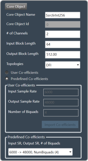
IIR Integer Multiple SSRC
This core object implements a synchronous sample rate converter whose input sample rate / input block length and output sample rate / output block length are integer multiple of each others. This is also an infinite impulse response implementation (IIR).
The object operates in one of 2 modes:
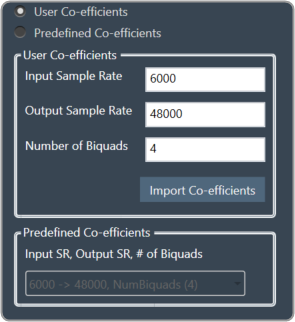
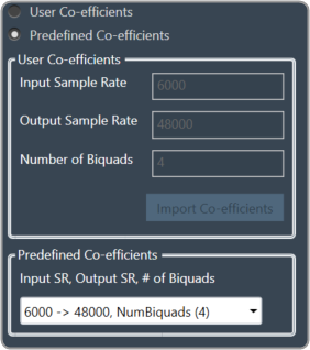
- User Coefficients mode
- Predefined Coefficients mode
Before we get into the details, there are some common configuration parameters between the two.
- The input block length needs to be set by the user.
- The Biquad filter topology. Currently 2 topologies are exposed.
- Direct Form I
- Direct Form II
User Coefficients mode: In this mode, the user has to provide the input and output sample rate. Input and output sample rates should not be equal. The Number of Biquads field is read-only.
User has to import the coefficients by clicking on the button “Import Co-efficients”. Based on the number of coefficients in the file, the Number of Biquads is updated.
Validations for User Coefficients mode: The Input and Output sample rates cannot be the same. Validation is shown when the same values are entered.
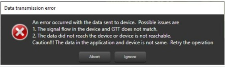
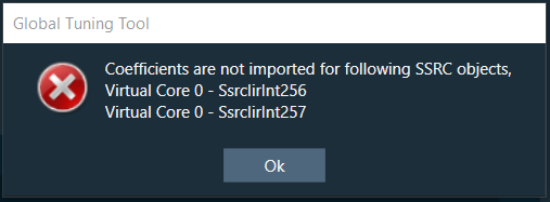
After adding a new “Ssrc lir Int” object and selecting “User Coefficients Mode”, if the coefficients are not imported, the following message will be displayed on various operations such as “Save”, “Edit Device”, “Copy Core Objects” and “Paste Core Objects”. After importing coefficients, the user can perform the required operation.
Predefined Coefficients mode: In this mode, the xAF dll is used to read the input sample rate, output sample rate, and the number of biquads. When a value in the combo box is selected, the xAF dll is also used to fetch the corresponding coefficients.
Biquad Co-efficient has to be re-imported whenever the mode is switched between Predefined Co- efficient mode to User Co-efficient mode.
For these pre-defined coefficients, the quality measures are as follows:
- Signal to noise ratio: 80 dB
- Total harmonic distortion: 2e-3f
- Spurious free dynamic Range: 59 dB
- Total harmonic distortion plus noise: -60 dB
- Frequency response flatness: 3 dB
Output block length (Displayed as a read-only field) = (Output sample rate /Input sample rate) * Input block length.
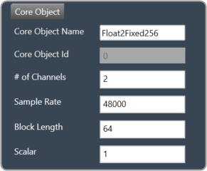
Float to Fixed
Float to Fixed core object accepts audio buffers that are in floating point format and outputs buffers that are in fixed point format (16-bit, 24-bit, 32-bit etc).

- # of Channels is configurable. No of Input channels = No of Output channels
- The user can configure the scalar value to indicate what fixed point format is required. This scalar value is multiplied by the floating point input samples to convert them to fixed point.
For example, to convert from float to 32 bit fixed point, this scalar value must be:
(1 << (32-1) – 1) = 2,147,483,647
- In order to make routing from any core object to Float2Fixed object both the source core object and Float2Fixed core objects sample rate and block length should match.
Float To Fixed core object is enabled for audio libraries version 16 and greater.
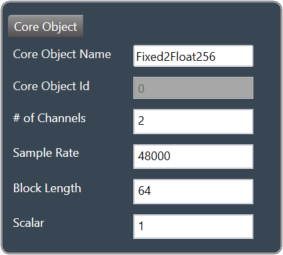
Fixed to Float
Fixed to Float core object accepts audio buffers that are in fixed point format (16-bit, 24-bit, 32-bit, etc) and outputs buffers that are in floating point format.

- # of Channels is configurable. No of Input channels = No of Output channels.
- The user can configure the scalar value to suit the fixed point format of the input samples. The reciprocal of this scalar value is multiplied by the fixed point input samples to convert them to floating point.
For example, to convert from 32 bit fixed point to float, this scalar value must be:
(1 << (32-1) – 1) = 2,147,483,647
- In order to make routing from any core object to Fixed2Float object both the source core object and Fixed2Float core objects sample rate and block length should match.
Fixed To Float core object is enabled for audio libraries version 16 and greater.
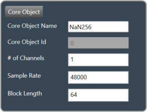
Nan Detector
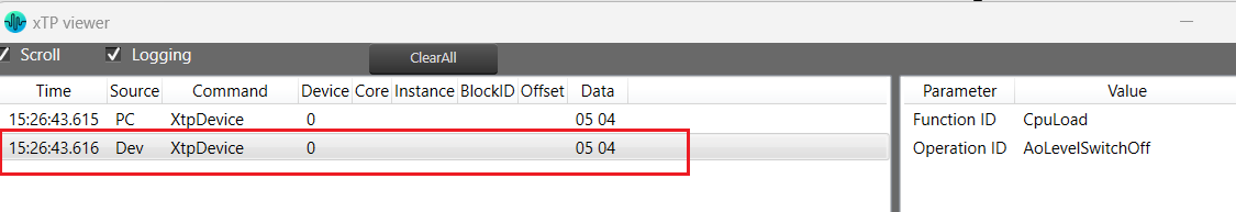
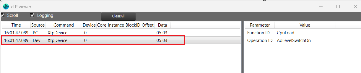
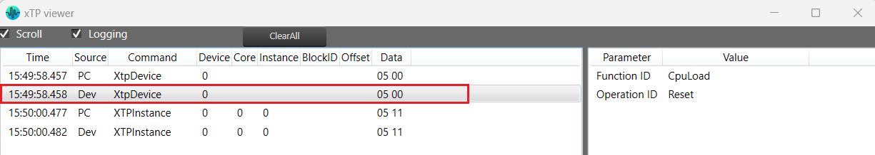
The NaN (Not a Number) detector core object detects NaN from input samples and informs the platform using an xTP command if NaN is found. The xTP command will inform about the core id, core object instance id and channel index, so that platform can react accordingly by muting or resetting states. The input samples are copied to the output without doing any other processing. The number of output channel(s) is always same as the number of input channel(s).

- # of Channels is configurable. No of Input channels = No of Output channels.
- Block length and Sample rate are configurable.
- The number of input channels is user configurable and ranges from 1 to 255.
- This core objects’ block length and sampling rate are the same at both input and output side.
- Block length is configurable in the range of 4 to 4096 samples.
- Sample rate is configurable in the range of 8 kHz to 192kHz.
In order to make routing from any core object to NaN Detector, both the source core object and NaN Detector core objects sample rate and block length should match.
NaN Detector core object is enabled for audio libraries version 19 and greater.
Core Objects Validation
When the GTT is loaded with a version of the xAF library lower than 13. If a user tries to open a device view that contains core objects other than a XAF instance, they will see the following error message.
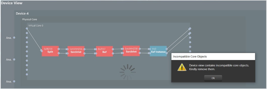
Aside from the Xaf instance, every other core object will be red.