Parameter Address Editor

The Parameter Address Editor allows you to add or remove parameters linked to a control. It is accessed in the Custom Panel Designer Tab from Properties, Parameters, Address or with a right click on the control and selecting Edit parameters.

The top section of the parameter address editor shows all available parameter assignments Device, Object and Parameter.

  • Device, Object, and Parameter Search: Since there are often a large number of items in the Device, Object and Parameter lists, the Search window allows you to narrow down the number of items in that list. For example, if you want to narrow the search to all Crown, Output Faders you would enter these into the Search windows.
    The bottom half of the Parameter Address Editor shows assignments made to the control.
  • Add Assignment: On the top section, select the parameters to be added to the control. Only devices that have been added to the venue will display in the “device” column.
    Click the Add button or drag and drop the selection to the lower section. The parameters are assigned to the control.
  • Remove Assignment: Select the parameters to be removed from the control then click the Remove button.
  • Data Type: Shows the Address data type.
  • Device Address: A drop-down list showing current available device addresses.
  • Device Type: Shows type of device.
  • Device Name: Shows the name of the device given in the venue.
  • Object Address: A drop-down list showing current available object addresses.
  • Object Name: Shows the name of the object where the parameter resides.
  • Parameter Address: A drop-down list showing current addresses available for the selected parameter.
  • Parameter Name: The name of the selected parameter

Control IDS

The Control IDs are used to configure Custom Control IDs. Users can add, edit, export, and import Custom Control IDs data.
Graphical user interface Description automatically generated

To open the Control IDs

  1. On the Device View, click on the Control IDs. This opens the Custom Control IDs configuration window.
    The Custom Control IDs window shows all the custom control ID details.

To add the custom control ID

  1. On the Custom Control IDs panel, click on Add. This opens the Add Control Signal window, where the user can enter the details of the new custom control.

    You need to enter details in all fields. The maximum value of control should be greater than the minimum value. The Control ID range should be between 61440 to 65535.
  2. Click OK to save the custom control id details.

To edit the custom control ID

  1. On the Custom Control IDs panel, click on the Edit icon. This opens the Edit Control Signal window, where the you can update or change the custom control details.
  2. Click OK to update the custom control id details.

To delete the custom control ID

  1. On the Custom Control IDs panel, click on the Delete icon. This deletes custom control and also removes its associated data.

To export the custom control ID

Using the export option, all custom control data can be exported in the provided destination directory with the file extension *.csv.

  1. On the Custom Control IDs panel, click on Export. This opens the file directory.
  2. Navigate to the desired location and click Save to export the file.

To import the custom control ID

Using the import option, all the custom control data can be imported to GTT.

  1. On the Custom Control IDs panel, click on Import. This action opens the file directory.
  2. Navigate to the file location and click Open to import the file.

This action will import all the custom control pins from the file (with *.csv extension) in the custom control list.

A message will appear if the file is invalid or does not contain the required data.
Graphical user interface, text Description automatically generated

If GTT contains custom control IDs, it will ask for confirmation whether the user wants to overwrite them.

An error message will be displayed if the import file contains duplicate control IDs.
Graphical user interface, application, website Description automatically generated

Scale Editor

The Scale Editor provides a way to customize ticks on a fader or rotary control.

  • Type: Select between Real Values (default), Arbitrary or .
  • Real Values: Shows the actual values on the control. The Values may be edited.
    A screenshot of a cell phone Description automatically generated with medium confidence
  • Arbitrary: This shows the values of the table in two columns. The left column lists the actual values and the right column lists their corresponding labels.
    A screenshot of a phone Description automatically generated with medium confidence
  • : Default settings or the display settings from the device panel.
  • Ticks: List of the ticks shown on the control.
    • Add: Adds a new tick.
    • Remove: Removes the selected tick.
    • Default: Resets the ticks back to the default setting.
  • Manipulate Values: Edits the selected tick.
  • Value: Changes the actual value of the control.
  • Label: Sets what the tick will display as the control in the panel.
  • Generate New Values: Automatically Generate Ticks using the following properties.
  • Anchor: Reference point where the automatically generated ticks will cross.
  • Step: Sets the initial spacing between the anchor and the next tick.
  • Linear: Sets the spacing between each automatically created tick to the Step value.
  • Logarithmic: Spaces the automatically created ticks logarithmically with respect to the anchor.
  • Integers: Automatically changes the labels to integers starting with the lowest tick value at 0.

Graph Parameters Window

Graphical user interface Description automatically generated

  • Channel Setup: Brings up the Channel Setup window.
  • Reset Graph: Resets the graph back to its default state.
  • Parameter Setup
    • Current Channel: Select the current channel to edit.
    • Current Curve: Select the process for the channel that was selected above.
    • Addresses: Brings up the Parameter Address Editor window.

Channel Setup Window

Graphical user interface, application Description automatically generated

  • Number of Channels: Click the up/down arrows to select the number of channels.
  • PEQ per channel: Click the up/down arrows to select the number of parametric equalizers per channel
  • Xover/Bandpass per channel: Click the up/down arrows to select the number of crossover / bandpass filters per channel.
  • DeEsser per channel: Click the up/down arrows to select the number of DeEsser filters per channel.
  • FIR per channel: When available, Click the up/down arrows to select the number of FIR filters per channel.
  • Bandpass in Selector: When checked, displays the Bandpass in the graph.
  • Color Scheme: Choose the color scheme for the graph. Select from Channel Number, Band Number or Curve Index

LED Values Editor

The LED Values Editor allows you to define the display for specified values for an LED or LED Image.

Graphical user interface Description automatically generated

  • Value Items: Displays a list of possible values of the parameter.
  • Minimum: Sets the minimum allowable value.
  • Maximum: Sets the maximum allowable value.
  • Image: Brings up the Image Select window.
  • Color: Select a color for the LED.
  • Add: Add new Value Items.
  • Remove: Remove selected Value Item.
  • Validate: Authenticates the values.

Indication Configuration Editor

The Indication Configuration form allows you to make specifications for a system indicator or region control on a Custom Panel.
Graphical user interface Description automatically generated

  1. Select Devices for State Logic: The devices that will be included in this configuration.
  2. Conditions: The condition of the device that will facilitate the activation or deactivation events.
    Graphical user interface, text, application Description automatically generated
  3. Select Logic Threshold: What will cause the logic action to occur:
    – if the condition occurs on all devices.
    – if the condition occurs on at least one device.
    Graphical user interface, text, application Description automatically generated – if the condition occurs on a specified percentage of devices.

    The logic represented by the Conditions combined with the Threshold corresponds to AND/OR/Mixed logic.

  4. Activation Event: The action that takes place each time the specified device state occurs including launch preset and/or play audio file.
  5. Preset: The panel preset, device preset, or venue preset to be launched each time the device state occurs.
    Graphical user interface, text, application Description automatically generated
  6. Play Audio: The audio file that will play each time the specified device state occurs. It will continue to play to the end of the file unless the deactivation event includes stop audio.Browse and select the name of the file to play. Windows sounds are located in the “Windowsmedia” directory.
  7. Deactivation Event: The action that takes place when the event stops occurring, including launch preset and/or stop playing the audio file.
  8. Preset: The panel preset, device preset, or venue recall to be launched when the device state stops occurring.
    Graphical user interface, text, application Description automatically generated
  9. Stop Audio: Shuts down the audio file when the device state stops occurring.
  10. Display Text rather than LED (System Indicator Only): Instead of an LED , a text button can display alternating states. Check the box to the left and enter the text to show the ON and OFF states.
    Background pattern Description automatically generated with medium confidence

State Variable

The State Variable Explorer window allows you to view the memory layout of each device instance. It can also be used to send and receive tuning data.

To copy values of FloatArraySV type state variable to the Windows clipboard, press CTRL+ C in the table . The float values are located in the clipboard. The same can be achieved by using the context menu (Copy All) of the table.

File: Using the file options you can load and save the set file.

  • Load Set: To load a set file, click on “Load Set”. Browse the location of .set or .setr file and click “Open”. This loads the set or .setr file in State Variables explorer.
  • Save Set As: To save a set file, click on “Save Set As”. A dialog box will appear, where you can choose the folder to store the files (.set/.setr). Enter a file name and click on the “Save” button.

Target: Using target options you can send or receive tuning data from the connected device. When the device is connected you will get the following options.

  • Send Tuning Data
  • Receive Tuning Data
  • Receive State Data

Sort by: Using sort options you can sort the state variables and audio objects in the state variable explorer.

  • Name: To sort the audio objects or state variables based on their names
  • Block Id: To sort the audio objects or state variables based on audio objects block Id.
  • Object Type: To sort the audio objects or state variables based on audio object types.
  • HiQnet Id: To sort the audio objects or state variables based on audio object HiQNetIds.

When you click it the first time, it will sort in ascending order; the next time, it will sort in descending order, and so on.

Search: Using the search option, you can locate and highlight a matching record and move on to the next or previous matching data set.
It will search audio objects and state variables based on Name, Block Id and HiQnet Id.

Reset: The Reset option will clear all search and sort data and reset state variable explorer to default state.

Devices List

The Devices section allows you to perform the following actions:

  • Add a new device to the project.
  • The Discover Device option allows you to discover connected physical or virtual devices and GTT will interact with the target device to obtain the device information available on the device.
  • Display lists all the devices in a project.
  • Provides options to remove the device from the project.
    Graphical user interface, application Description automatically generated

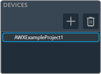
On the Device Designer tab, click on the (+) icon to add the device. This opens the Add Device dialog box.

On the Add Device, you can perform the following operations.

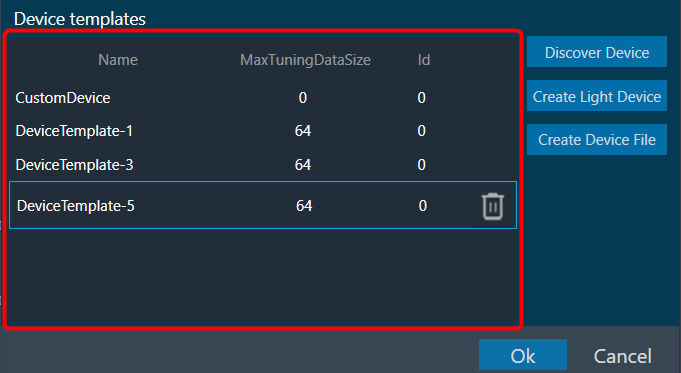
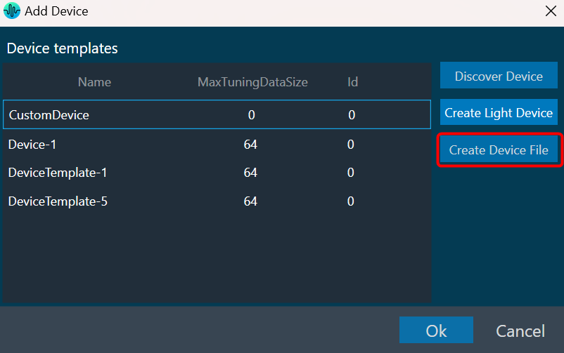
  • The Add Device dialog box lists existing device templates available in GTT.
  • You can add new device templates using any of the methods; Discover Device, Create Light Device, or Create Device File options.
  • You can delete existing device templates if they are not used in a project.
  • Custom Device is also listed in the Device template list as the first template. You can select a custom device and add it to the project like other templates.

GTT supports 1 custom device at a time as per the current design.

You can use any of the options to add a device template to the project.

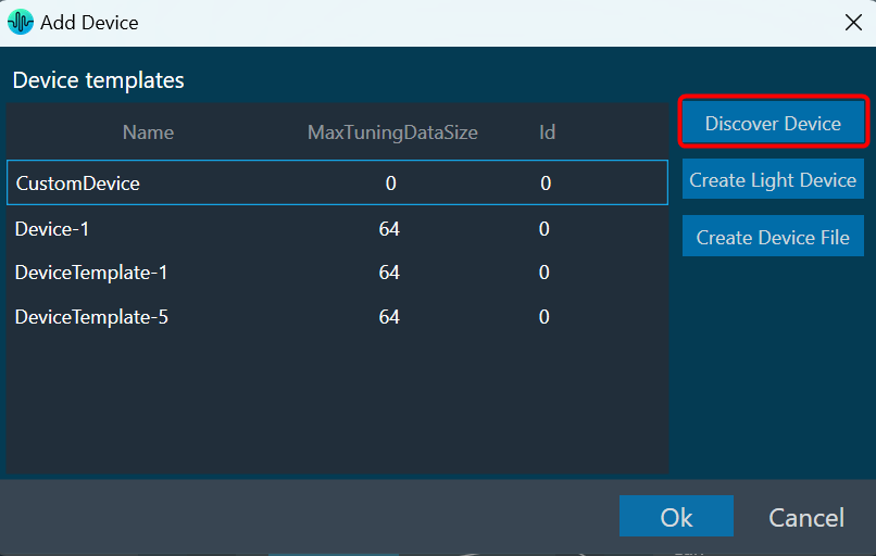
  • Discover Device: Click on Discover Device, if you have the preconfigured device template available and connected to the physical or virtual device.
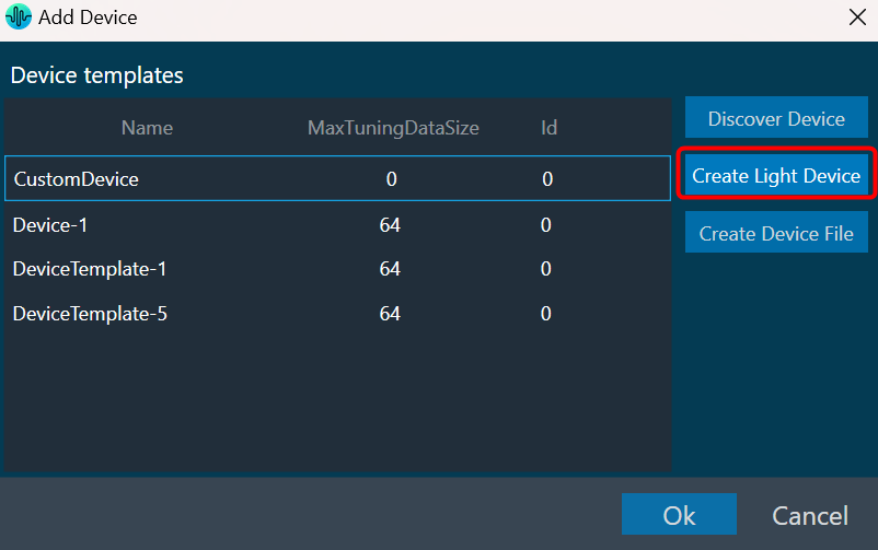
  • Create Light Device: Click on Create Light Device, if you want to create a new template.
  • Create Device File: Click on the Device file, if you want to create a device file.
  • Device Template Rename: Rename the selected device template post creating a light device, discover the device template, create a device file, or any existing device template.

Discover Device

The Discover Device feature allows you to read and write the device configuration from or to the device.

This function allows you to read information from a device that is connected to the Global Tuning Tool. This information is used to create a device template that reflects the internal layout structure of the device, which includes its physical cores, virtual cores, and routing information from device input to virtual cores between virtual cores and core objects.

You can also write (download) your configuration to the device using this feature.

Below are the few details that GTT will get from the device to construct the inner layout.

  • Physical cores information.
  • Core information.
  • Core objects information.
  • Device and Virtual Core Routing (For more details refer to Device Routing)

Below are the prerequisites to start a Discover a Device.

  • Copy the flash file (device.flash) and the audio library xAFVirtualAmp.dll file available in AWXInstalledLocation/HarmanAudioworX/AudioFrameworkDLLs to your working folder.
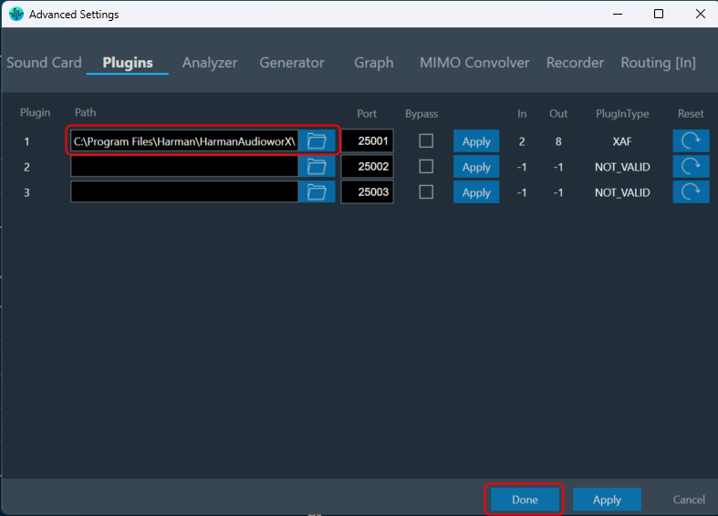
  • Launch IVP, open to “Advanced” settings, go to the “Plugins” tab and select the correct path to the xAFVirtualAmp64.dll.

Before using this feature, delete all the *.flash files from the working folder. IVP may crash, if it has the old tuning flash files.

Follow the below steps to discover a device:

  1. On the Add Device window, click on Discover Device. The GTT will start to communicate with the target device, gather the device information, and add the device to the device templates.

The device identification feature is enabled for audio libraries version 13 and higher.

Only after you have completed the prerequisites the Discover Device feature function will work properly.

Create Light Device

Using the Create Light Device option, you can create a new template.

Follow the below steps to create a device template:

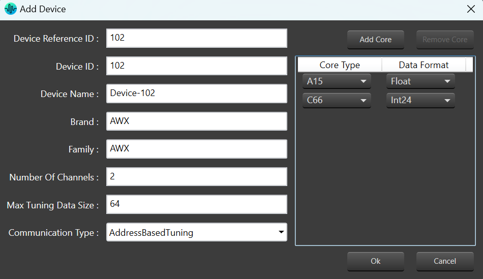
  1. On the Add Device window, click Create Light Device. This opens the Add Device dialog box.
  2. Enter the details in the following fields and configure the device core type.

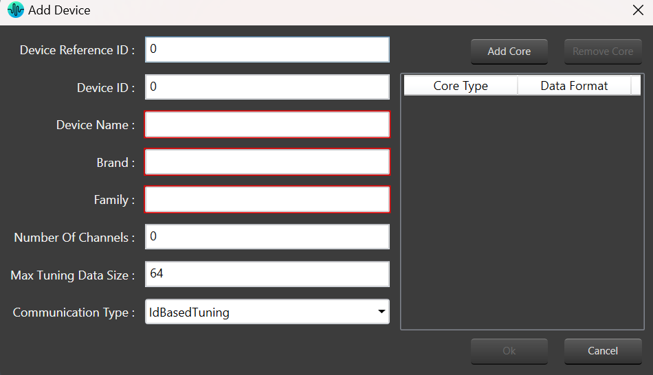
    • Reference ID: Enter the reference ID of the template.
    • Device ID: Enter the initial value of the Device ID field for the first device instance created out of that template Device template name.
    • Device Name: Enter the device name.
    • Brand: Enter the brand name required for legacy AA infrastructure.
    • Family: Enter the family name required for legacy AA infrastructure.
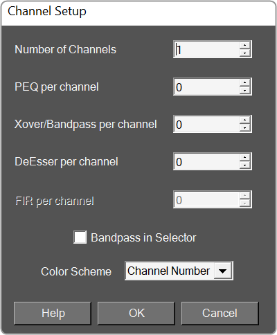
    • Number of Channels: Enter the number of channels supported by the device.
    • Max Tuning Data Size: Enter the maximum count of bytes included in a single tuning data message.
    • Communication Type: Select ID-based tuning or address-based tuning.
      • IdBasedTuning –
      • AddressBasedTuning –
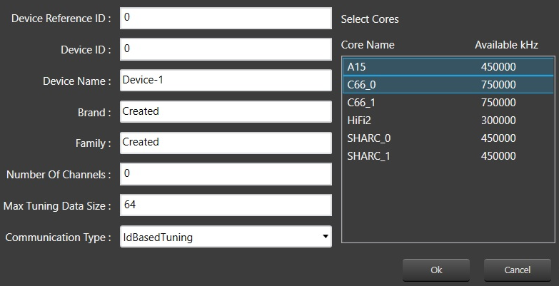
    • Core(s): Each device template exposes one or more physical cores.

    For the xAF library before the O release: multiple cores from the given list can be selected.
    Graphical user interface Description automatically generated
    For the xAF library from O release: Cores can be added/removed. Core types and Data-formats supported by xAF will be listed for configuring the core.
    Graphical user interface Description automatically generated

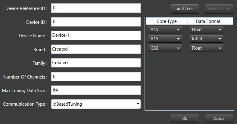
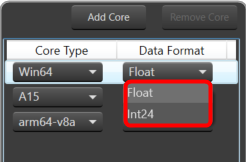
  3. Click Add Core, select core type and date format from the drop-down list, and then click Ok.
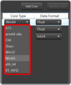
    When the default xAF library version is < 15 (O dll), GTT displays a static set of core types with corresponding data formats.
    Based on the default xAF library selected, you can add multiple cores, and two modes of core selections (Core Type and Date Formate) are available. Below is the example showing the available core type supported by respective xAF dll versions.
    Graphical user interface, application Description automatically generated  Graphical user interface Description automatically generated
    While configuring the core type of the device, if you want to remove any core, select the core, and click Remove Core.
  4. Click OK. The new template is added to the device templates list.

Create Device File

The GTT allows you to create a device flash file using Device File Editor (DFE) in a project. The device file is a combination of Physical Cores, Input Groups, and Output Groups.

Follow the below steps to create a device file:

  1. On the Add Device window, click Create Device File.

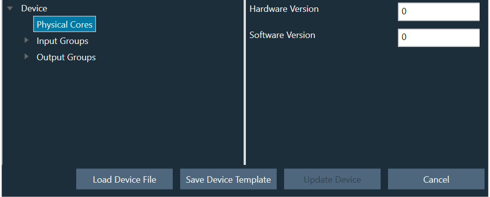
    This opens the Device File Editor window. The editor interface uses a tree-like structure to display items at each level and this structure is defined in the xTP specification. Furthermore, a Virtual Core will have Input and Output Groups as defined by the xTP specification. Each Input Group and Output Group have one group added by default.
    By right-clicking on each item, a context menu will appear that will allow you to add or remove subtree items.
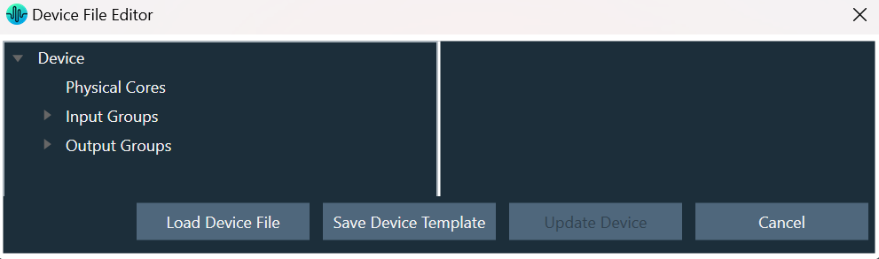
  2. Select Physical Cores and enter the hardware and software version.
    There could be one or more Physical cores under a Device and each Physical core can have more than one virtual core inside it.
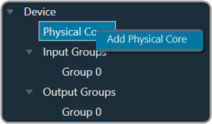
  3. Right-click Physical Cores and select Add Physical Core.
    A screenshot of a computer screen Description automatically generated with medium confidence
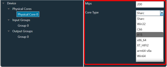
  4. Select Physical Cores 0You must specify the Core Type of Physical Core. When the default xAF library is set to O release or above, the supported xAF core-types will be listed or set the default value to ‘0’.
    Text Description automatically generated with medium confidence
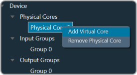
  5. Right-click on Physical Cores 0 and select Add Virtual Core.
    A screenshot of a computer Description automatically generated with medium confidence
  6. Select Virtual Core 0, enter the Task Priority, and select the Date Format.
    A picture containing treemap chart Description automatically generated
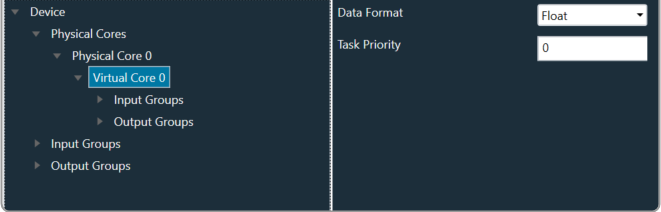
    A Virtual Core is made up of Input and Output Groups. You can add one or more Physical Cores, and each Physical Core can have many Virtual Cores.

    It is important that you should specify the Core-type of the Physical Core, Data Format of the Virtual Core, Device Input, or Output Group.

    When the selected default xAF library is “O” release or above, the xAF supported data formats will be listed or the default value set to ‘2’.

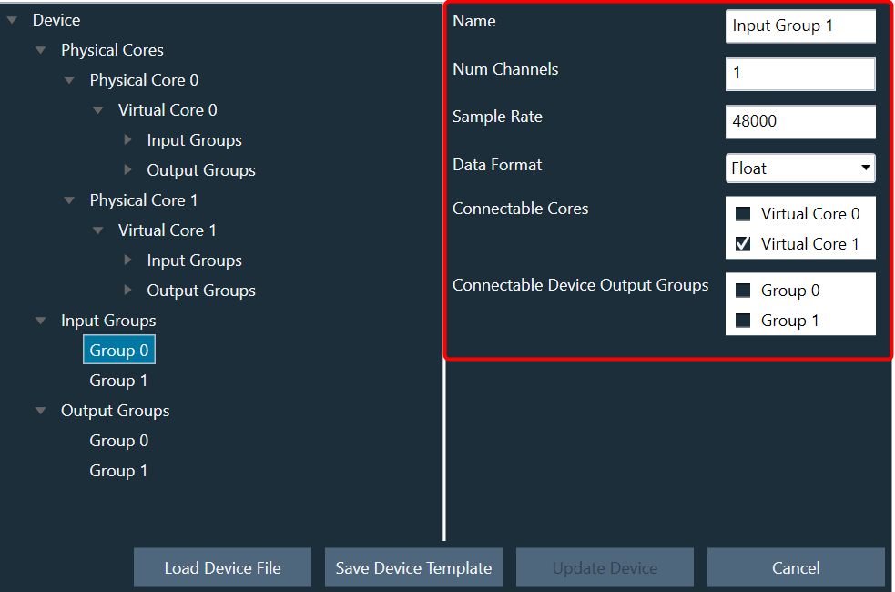
  7. Expand Input Groups, select Group 0, and configure the respective properties. Similarly, expand Output Groups, and configure Group 0. In order to allow routing from Device Input/Virtual Core to other Virtual Cores or Device Output Groups, select Connectable Cores and Connectable Device Output Groups.
    You can add multiple Groups inside an Input Group.
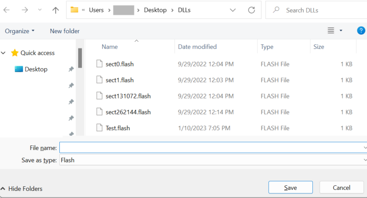
  8. Once all the configuration is done, click Save Device File. A save file dialog box appears, enabling you to save the flash file.
    The flash file contains the information related to the  structure of the device like Device ID, hardware version, software version, input groups count (No. of input pins), output groups count (No. of output pins), physical cores count,
    Graphical user interface, application Description automatically generated
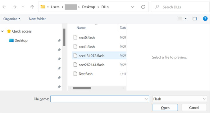
    To view or modify an existing flash file, click Load Device File. The Device File Editor displays an Open file dialog box, selects the flash file, and clicks Open.
    Graphical user interface, application Description automatically generated

Device Template Rename

You can rename the selected device template post creating a light device, discovered device, or any existing device template.

Custom devices would not have the option to rename the template name.

Device name once edited, any device created using this template will have the appropriate name reflected in Class Name, reflecting the template on which the device is based.

To Edit the name, press the edit button, which will show an editable section with the selected device name in it.

Upon editing the name click on “Ok” and the template name will be applied. The device name allows only alphabet, numeric, and hyphen (-) and has a limit of min 1 character and max 55 characters.

When there is a validation error in the name, the “Ok” option will be disabled, and the edit box will be shown as red.

Device template name is also retained when exporting or importing the project. Name of imported device template would be based on existing uniqueness naming rules.

External Endpoints

GTT allows external tools to interact with devices. The tuning of 3rd  party audio objects can be done directly in GTT, or it can also be done from an external tool.

The requests from external tuning tools will come to GTT and GTT will forward these requests to the device. This is enabled through a WCF service endpoint that external tools can tap into.
To help external tools integrate with GTT, the GTT process hosts a WCF endpoint; external tools can connect to that endpoint and use the exposed APIs.

Refer the contact information mentioned in the latest release notes to get more details on “External third party tool” documentation and package.

By default External Endpoints will use port 8080 for the communication.

Before proceeding with the following sections, it is understood that you have received 3 compressed zip files. It is recommended that you use these for integration purposes.

  • HarmanReferenceTool.zip: This compressed folder contains an executable sample tool that you can run and verify the endpoint functionality. Unzip the HarmanReferenceTool.zip file, go to the HarmanReferenceToolReleasenet6.0-windows folder, and locate the ExternalTuningTool.exe. Run the exe to open Harman Reference Tool.
  • ExternalToolCode.zip: This compressed folder contains visual studio solution for the sample tool. One can refer to this code to understand how the endpoint is accessed. Unzip the ExternalToolCode.zip file and locate the file under ExternalToolCodeExternalTool.
  • WcfServiceProxyLib.zip: This compressed folder contains a proxy library dll that should be referenced for integration with the GTT endpoint.

The “WcfServiceProxy.dll” is a .net dll which has the implementation of the client code for the endpoint hosted in the GTT.

By default Third Party tuning tool will use port 8080 for the communication.

Setup

GTT needs a minimum setup for external endpoints to function.

  1. Right-click on GTT launcher and click on the “Run as administrator” option.

    For the external endpoint feature to work correctly, it is necessary to run GTT as an administrator.

  2. GTT should have an open project. Only external audio objects can be accessed from external tools.
    Accordingly, the project must contain at least one external audio object within the signal flow. An external audio object is defined as an object with Class ID between 9000 and 9999.
  3. GTT should be connected to the device. The device can be a virtual device or a physical board.
  4. Click on the Start/Stop button to start the External Endpoint. The same button works as a toggle switch to start and stop the endpoint.

    A license is required to use this feature. Contact the solution management team to enable the feature.

  5. Once the endpoint is hosted,  the 3rd party applications can use the proxy dll or write their own proxy to access the WCF endpoint. For more details about WCF proxy, refer to “About WcfServiceProxy.dll in the GTT Third Party Tool Integration User Guide. 

Supported Features

Sending and Receiving Tuning Data

To support sending and receiving tuning data, the following methods are exposed.

  • GetExternalAudioObjects: This method will return all the 3rd party audio objects in the device.
  • SendTuningDataAsync: This method is used to send tuning data to audio object.
  • ReceiveTuningDataAsync: This method is used for receiving tuning data from an audio object.

Sending and Receiving Control Data

To support sending and receiving control data, the following methods are exposed.

  • SendControlDataAsync: This method should be used to send control data by mentioning the control id and control data.

    The control data supports 16.16 format.

  • ReceiveControlDataAsync: This method can be used for retrieving control data by providing the control id to the control elements to be read back.

Streaming Methods

GTT also supports streaming with the following methods.

  • EstablishSocketConnection: This method must be called first in order for streaming to work. The third-party tool should first establish a socket connection and then make a call to the port number where it is listening. GTT will connect to that port. This is a socket connection.
  • DisconnectSocketConnection: This method is used to unsubscribe all the subscriptions and close the socket connection.
  • SubscribeForStreamDataAsync: This method is used to subscribe for stream data for an audio object.
  • UnSubscribeForStreamData: This method is used to stop or unsubscribes the stream data.

To know more about all the API methods described above, refer to the API Reference section in the GTT Third Party Tool Integration User Guide. 

External Tool Interaction

The following are the steps to integrate with GTT.

By default GTT will host the WCF endpoint on this URL (http://localhost:8080/XtpHandlerService).

Steps to get started with the WCF service.

  1. Discover the service using this URL. Use the known tools like visual studio service reference tool or any 3rd party tools.
  2. Create a service reference for the same.
  3. Then using the service reference call the APIs for different operations.

Otherwise, developers can follow the “Third Party Tool Tuning Sequence Workflow” and  “Third Party Tool Streaming Sequence Workflow”  to write code to consume the endpoint hosted by GTT using the proxy library (WcfServiceProxy.dll) shared and explained in the GTT Third Party Tool Integration User Guide. 

API References

GTT endpoint APIs definition and parameter details are provided in the GTT Third Party Tool Integration User Guide. 

API: ExternalAudioObject

API Function:

ExternalAudioObjectResponse GetExternalAudioObjects();

Description: This function will return all the audio objects that are used in the currently open signal flow in GTT. It returns only those audio objects which have Class ID between 9000 and 9999. Also, any audio objects that are listed in external category.

API: SendTuningDataAsync

API Function:

Task SendTuningDataAsync(ExternalAudioObject audioObject, int subBlock, int offset, byte[] data);

Description: This function will apply the data payload to the ExternalAudioObject  passed into the function.

API: ReceiveTuningDataAsync

API Function:

Task< XtpEndpointResponse > ReceiveTuningDataAsync(ExternalAudioObject audioObject, int subBlock, int offset, byte[] size);

Description: This function will retrieve tuning data from the ExternalAudioObject.

API: SendControlDataAsync

API Function: 

XtpEndpointResponse SendControlDataAsync(int controlId, byte[] data);

Description: This function will send control data to the control id mentioned in the function.

API: ReceiveControlDataAsync

API Function:

XtpEndpointResponse ReceiveControlDataAsync(int controlId, byte[] data);

Description: This function will get the control data from the control id that is passed into the function.

API: EstablishSocketConnection

API Function: 

XtpEndpointSocketResponse EstablishSocketConnection(int port);

Description: This function will instruct GTT to connect to the socket connection listening at the port passed as parameter. The integrating application will create a socket connection and listen at a port and send this port id to GTT, so GTT can establish a connection and send stream data through the socket.

API: DisconnectSocketConnection

API Function: 

XtpEndpointSocketResponse DisconnectSocketConnection(int port);

Description: This function will instruct GTT to disconnect the previously established connection. The integrating application will close the socket connection.

API: SubscribeForStreamDataAsync

API Function:

Task SubscribeForStreamDataAsync(ExternalAudioObject audioObject, int subBlock, int messagesPerSecond, bool beforeCalc);

Description: This function will create a subscription for data streaming of a particular state variable of the audio object mentioned at subblock/offset.

This function can be used to subscribe for streaming of a particular data from audio object. Parameters include audio object, its subblock. There is an option to send the number of messages to be streamed per second and if the streaming data is to be retrieved before calc or after calc.

All this needs to be supported by the audio object. Once the subscription is complete, the subscription id and status are returned to the object.

API: UnSubscribeForStreamData

API Function: 

SubscriptionResponse UnSubscribeForStreamData(Guid subscriptionId);

Description: This function will terminate the subscription that is currently running. GTT will stop the subscription that is started with the subscritionId passed as parameter.

Use Cases and Workarounds

Use Case Workarounds
Use Case 1: While starting External Endpoints from GTT, if you gets notification of port already being used.
Then you need to perform configuration in GTT as well as in ExternalTuningTool.
Close the GTT application and perform the below configurations:

By default the key does not exists in the config file. When configuring the config file, you need to add the key and the required port number.

GTT configuration settings:

  1. Open config ‘GlobalTuningTool.exe.Config‘ from install path ‘..HarmanHarmanAudioworXtoolsGTT’.
  2. Under “appSettings” section, add a key ‘HarmanExternalEndPointPort‘ and provide any value from range from 8081 to 65535.
    This key and value will be used to host the service on provided port for the communication.
  3. Launch the GTT application.

ExternalTuningTool configuration settings:

  1. Open config ‘ExternalTuningTool.dll.config‘ from path ‘…….ExternalToolExternalTuningToolbinDebugnet6.0-windows’ or from ‘…….Releasenet6.0-windows’.
  2. Under “configuration” section, add appSettings section, add key ‘HarmanExternalEndPointPort‘ and provide any value from range 8081 to 65535.
    This key and value will be used for communication.

Key name must be ‘HarmanExternalEndPointPort’ and value must be same in GTT config as well as in ExternalTuningTool config.