Native Panels

The Native Panel is a user interface which contains graphical element or component that allows you to interact with various parameters of audio object and allows you to easily tune complex audio object.

These panels can provide options to adjust settings, routing audio signals, applying effects, and more.

Below is a list of audio objects that support native panels.

Audio Object Audio Object Panel


Real Time Analyzer Components

The Real Time Analyzer (RTA) is a tool used to measure and analyses sound waves in real-time. RTA typically consists of several features, that are grouped into various categories to help you navigate and utilize the tool effectively.

Following are components of Real Time Analyzer:

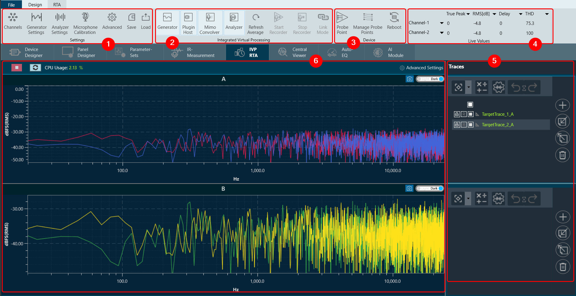
1. Settings: In an RTA (Real Time Analyzer) window, you can configure various types of settings, that includes:

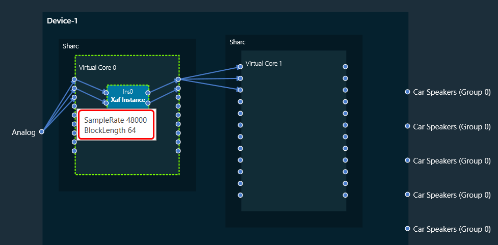
2. Integrated Virtual Processing: In the Integrated Virtual Processing group of an RTA (Real Time Analyzer), you can find various types of processing options that allow you to generate and analyze the audio data. For more details refer Integrated Virtual Process.
Below are the processing options included in IVP.

  • Plugin Host
  • Mimo Convolver
  • Analyzer
  • Refresh Average
  • Start Recorder
  • Stop Recorder
  • Link Mode

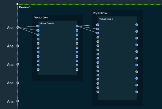
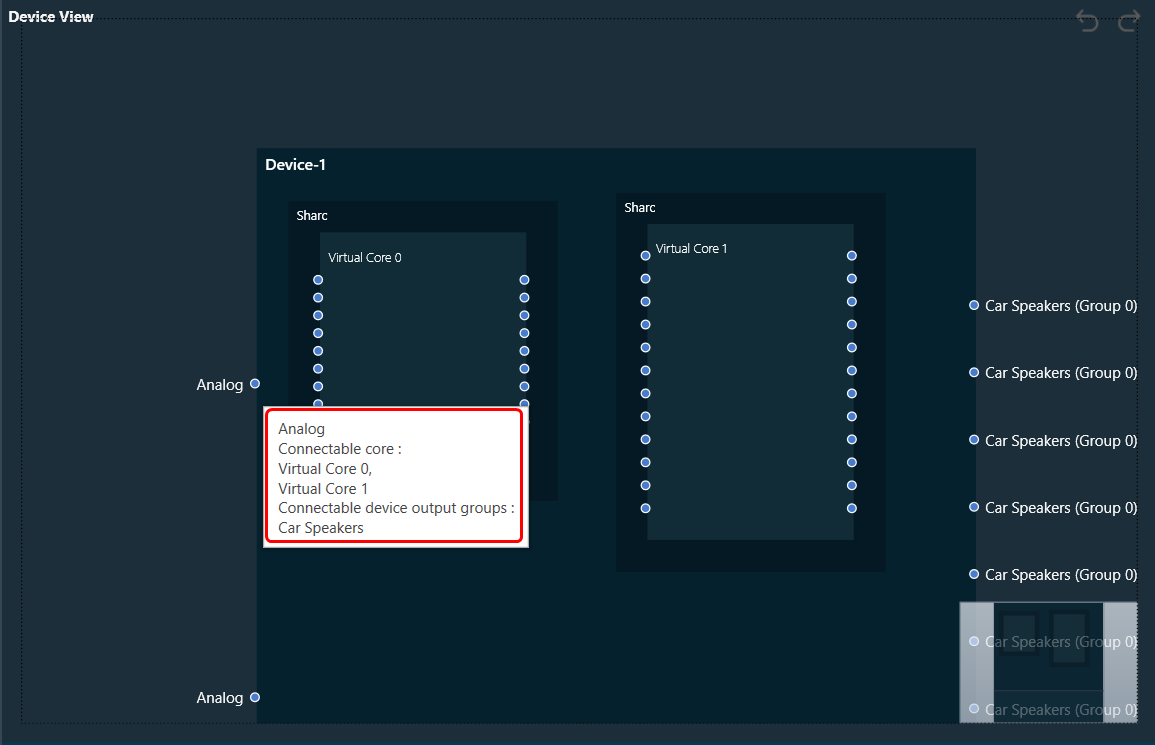
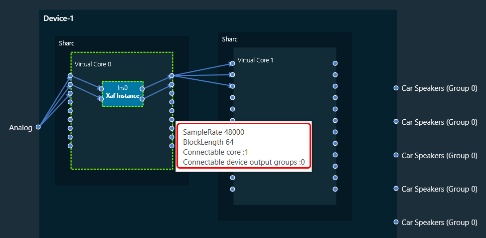
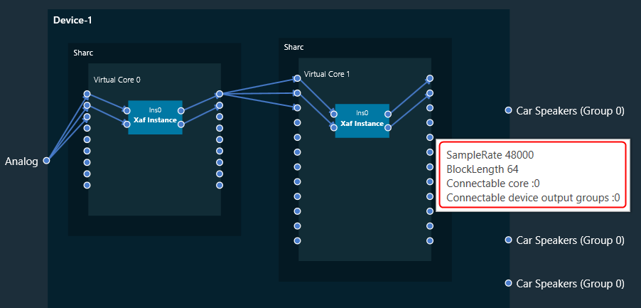
3. Device: This group enables you to manage the probe points of your device. Additionally, it supports the streaming of data from any point in the signal flow back to GTT, allowing for analysis, recording, or reuse of the data within IVP. Below are features included in the group Probe Point Configuration.

4. Live Values: In the section, you can easily view the real time values of RMS, THD, Peak, Peak-Frequency, and THD+N for selected two channels. For more details refer to Real Time Data view.

5. Traces: The trace in RTA is a captured measurement curve. Traces provide the ability to plot multiple measurement curves captured at different times on the same graph, allowing for easy comparison of measurements. For more details refer to Traces.

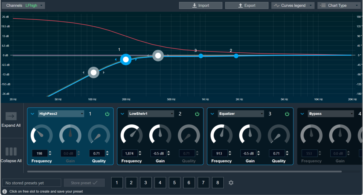
6. Graph Analyzer: This section shows a graph of the audio signal, which enables the analysis of the spectrum of the audio signal. For more details refer to Graph Settings and Measurement.

Routing (Connections)

Routing in device view is supported at different levels

Device Routing


  • User can connect starting from input of the Device to any virtual core inside it.
  • Routing is also possible between the virtual cores. i.e., A virtual core output could be connected to the input of another virtual core.
  • 1:N routing is supported at this level. i.e., A device input can connect to multiple Virtual Cores. And a virtual Core Output could be connected to multiple virtual core inputs.
  • Not all the device inputs can connect to all Virtual Cores and similarly not all Virtual Cores can be connected to each other. There are few validations put in place. Please find the below list of validations for device routing.

Validations

  • Based on the information available on the Device, the connectable cores for a Device input is displayed whenever the user hovers on the input connection pin. Also, the connection pin name is displayed on hovering the mouse. The below image indicates the Device input pin 2 can be connected to Virtual Core 0 or Virtual Core 1.
  • Each Virtual Core is associated with some Sample Rate and Block Length. This information could be seen when hovered over the Virtual Core Pin.
  • Based on the information available on the Device, the Connectable cores and Connectable device output groups for a Virtual core output is displayed whenever the user hovers on the output connection pin. The below image indicates the Virtual core 3 output pin 3 can be connected to Virtual Core 4 or 5 or Device output group 0, 1 or 2. Virtual Core Outputs can connect to other virtual core inputs even if the sample rate and block lengths do not match.
  • Device output group can be known by hovering on the device output pin. In the below image the pin Speaker belongs to Group 0.

Core Routing


  • User can connect starting from input of the virtual core to core objects inside it and then to the output of the virtual core.
  • Connecting the virtual core input to its output is not allowed. A core object has to be put in between virtual core input and output pins.
  • For connecting between the instances, both the connecting core objects should have same block length and sample rate.
  • If there is a need to connect two instances with different Block Length/Sample Rate, then user may use a Buffer/SSRC_IIR objects to get the desired output.

Device identification feature will only be enabled for audio libraries versions 13 and greater.