Harman Logo
AUDIOWORX
  • Home
  • Documentation
  • Videos
  • Release Notes
  • Login
Harman Logo
AUDIOWORX
  • Home
  • Documentation
  • Videos
  • Release Notes
  • Login
Harman Logo
AUDIOWORX
  • Home
  • Documentation
  • Videos
  • Release Notes
  • Login
  • Getting Started
  • User Guides
  • Developer Guides

Table of Content

Global Tuning Tool

  1. About Global Tuning Tool
    1. System Requirements
    2. Global Tuning Tool Workflow
  2. Workspace Overview
    1. Home Screen
      1. Home screen Options
      2. Application Options
    2. Device Designer Overview
      1. Tools
      2. Connection
      3. Import and Export
      4. Tuning
      5. Device Panels
    3. Devices and Template View
    4. About Core Objects Toolbox
    5. Device Operations
    6. Properties Panel
    7. Device View
    8. Help
  3. Configurations
    1. Configure State Variable
    2. Configure Default Control-Ids
    3. Configure Preset Controller
      1. Configuring Controller Slot
      2. Core Object Settings
      3. Custom Actions Settings
      4. Exporting Preset Configurations
      5. Maintain Folder Structure
      6. Loading Slots on the Device
      7. Handling Dual Responses
      8. Send Preset Data Online
    4. Link Window
    5. Configure Controller
    6. Launch MIPS Profiling
    7. Launch Memory Profiling
    8. Editing Memory Latency
    9. Configure Streaming and Polling
      1. Start Live Streaming
      2. Record Streaming Data
      3. FFT for Streaming
    10. Configure File controller
    11. Configure Control IDS
    12. Custom Device Usage
    13. Multi-xAF Library Support
    14. Configure External Endpoints
  4. Operations
    1. Create a New Project
    2. Create Signal Flow
    3. Connecting a Device
    4. Routing (Connections)
    5. Device Synchronization
    6. Launching Multiple Signal Flows
    7. Tune a Signal Flow
  5. Designing Custom Panel
    1. Panel Designer Ribbon
      1. Text Design
      2. Fader Design
      3. Rotary Design
      4. Button Design
      5. Box Design
      6. LED Design
      7. Meter Design
      8. Other Design
      9. Images
      10. Advanced
    2. Panels View
    3. Custom Panel Properties View
    4. Designer Workspace
    5. Editor Windows
      1. Parameter Address Editor
      2. Multi-Parameter Address Editor
      3. System Function Editor
      4. State Indication Setup Window
      5. Select Color Window
      6. Discrete Values Editor
      7. Indication Configuration Editor
      8. LED Values Editor
      9. Graph Parameters Window
      10. Scale Editor
    6. Create a Custom Panel in GTT
  6. Working with Parameter Set
    1. Parameter Set Overview
      1. Configuring Parameter Data
      2. Apply Delta in Parameter Sets
      3. Retrieve and Verify Parameter
      4. Import and Export Set File
      5. Preset Comparison
      6. Parameter Sets Explorer Color
      7. Switch Between Multiple Parameter
      8. Saving and Loading Set File
      9. Search in Parameter Sets
    2. Create a Parameter Set in GTT

Signal Flow Designer

  1. Overview Of Signal Flow Designer
  2. Components of Signal Flow Designer
  3. Operations in Signal Flow Designer
    1. Pin Labelling
    2. View Audio Object Metadata
    3. Column Name Configuration Panel
    4. Upgrade Audio Object
    5. Audio Object Processing State
    6. Metering the Signal Flow
    7. Copy and Paste Operation
    8. Undo and Redo Operation
    9. Block Control
    10. Signal Flow Design Validation
    11. Securing Audio Objects
  4. Create a Signal Flow
  5. Tune a Signal Flow
  6. Native Panels
    1. Launching Native Panel
    2. Common Operation in Native Panel
    3. Configuring Custom Native Panels
  7. Additional Audio Parameters
  8. Harman Audio Library Service
  9. Multiple Framework Instances Support
  10. Feedback loop in Signal Flow
  11. Compound Audio Object
    1. Create a Compound Audio Object
    2. Import and Export CAO
    3. Tuning and Editing CAO
    4. Create Preset for CAO
    5. Edit CAO Instance
    6. Set password for CAO
    7. Linking Custom Panel to CAO
    8. Multi dll support for CAO
    9. Delete a Compound Audio Object

Audio Object Description

  1. Audio Object Description Overview
  2. Interface Objects
    1. AudioIO
    2. ControlIn
    3. ControlOut
  3. Basic Objects
    1. Delay
      1. Delay Panel
    2. Gain
      1. Gain Panel
    3. Level Monitor
      1. Level Monitor Panel
    4. FaderBalance
      1. Fader Balance Panel
    5. Volume and Mute
      1. Volume and Mute Panel
    6. VolumeLite
  4. Control Objects
    1. Control Math
    2. Control Grouper
    3. Control GroupSplitter
    4. Control Multi Adder
    5. Control Mixer
      1. Control Mixer Panel
    6. Control Router
      1. Control Router Panel
    7. Control Smooth
    8. AudioToControl
    9. Lookup Table (LUT)
      1. Lookup Table (LUT) Panel
  5. Routing Objects
    1. Router
      1. Router Panel
    2. Splitter
    3. Demux
    4. Selector
  6. Source Objects
    1. Noise Generator
      1. Noise Generator Panel
    2. Wave Generator
    3. FilePlayer
  7. Mixer Objects
    1. Adder
    2. Matrix Mixer
      1. Matrix Mixer Panel
    3. Merger
    4. Fader Matrix
  8. Dynamic Object
    1. Limiter
      1. Limiter Panel
  9. Filter Objects
    1. ParameterBiquad
      1. Parameter Biquad Panel
    2. CoefficientBiquad
      1. Coefficient Biquad Native Panel
    3. Tone Control Extended
      1. Tone Control Extended Panel
    4. XoverBiquad
      1. Xover Biquad Panel
    5. FastConv
      1. Fast Conv Panel
    6. FIR Filter
      1. FIR Filter Panel

Real Time Analyzer

  1. Real Time Analyzer Overview
  2. Real Time Analyzer Components
  3. Settings
    1. Channels Settings
    2. Generator Settings
    3. Analyzer Settings
    4. Microphone Calibration
    5. RTA Advanced Settings
      1. Sound Card Settings
      2. Plugin Host Setting
      3. Advance Analyzer Settings
      4. Advance Generator Settings
      5. Graph Display Settings
      6. Mimo Convolver Settings
      7. Recorder Settings
      8. Routing Settings
    6. Saving and Loading RTA File
  4. Integrated Virtual Process Options
  5. Probe Point Configuration
  6. Real Time Data View
  7. Graph Settings and Measurement
  8. Traces
    1. Trace Toolbar
    2. Trace Configuration
    3. Trace Functionalities
    4. RTA Shortcuts
  9. Analysing Audio Signal

Measurement Module 2.0

  1. Measurement Module Overview
  2. Configurations
    1. Device Output Mapping
    2. Generator
    3. Test Sound
  3. Understand Measurement Process
    1. Scene Setup
    2. Speaker Configuration
    3. Microphone Configuration
    4. Define Measurement
    5. Measurement Session

Central Viewer

  1. Central Viewer Overview
  2. Central Viewer Window
    1. Configurations
    2. Scene Mode
    3. Chart Selector
    4. Waterfall Chart
    5. Graph Area
    6. Curve Lists
    7. Domain Selector
  3. Import Export Central viewer settings

Starter Kit Utility Tool

  1. Starter Kit Utility Tool
  2. Useful Commands for Starter Kit
  3. Starter Kit Troubleshooting
  • Global Tuning Tool
  • Create a Custom Panel in GTT

5.6.Create a Custom Panel in GTT

Follow the below steps to create a new panel.

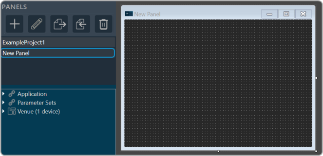
  1. Navigate to the Panel Designer tab.
  2. Go to Panels view and click on the (+) icon.
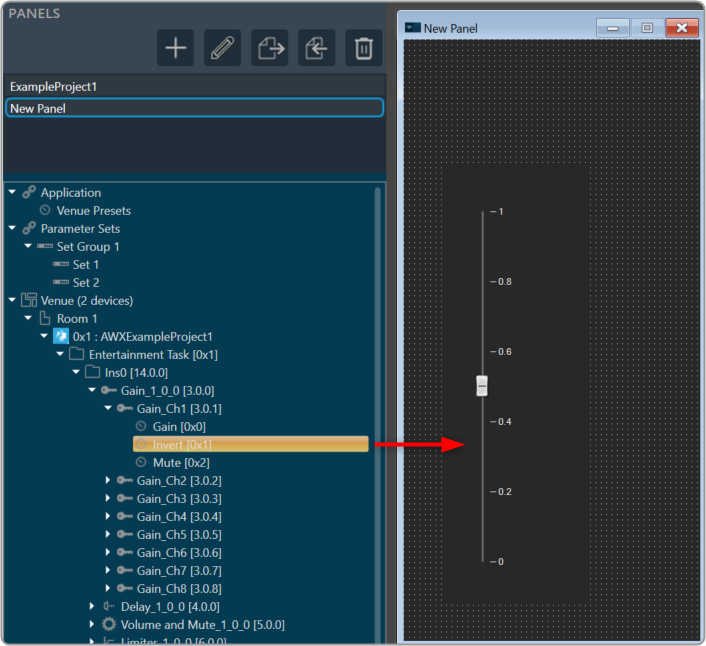
  3. Enter the name of the panel and click OK. The newly created panel add to the panel list.In the Panel view, select the new panel. The designer workspace of the new panel opens.

Add State Variables to Panel

Before adding StateVariables, make sure you have added a device to GTT. For information on how to add a device, refer to Create a New Project.

There are two ways to add StateVariables to a custom control panel.

  • Option 1: Drag a StateVariable and choose a control.
  • Option 2: Add a control and assign a StateVariable.

Option 1: Drag StateVariable and choose control:

  1. Go to Panels view, expand the cores of your device, and drag-drop a StateVariable to a free space in the custom designer panel. A dialog box opens showing all the basic control tools.
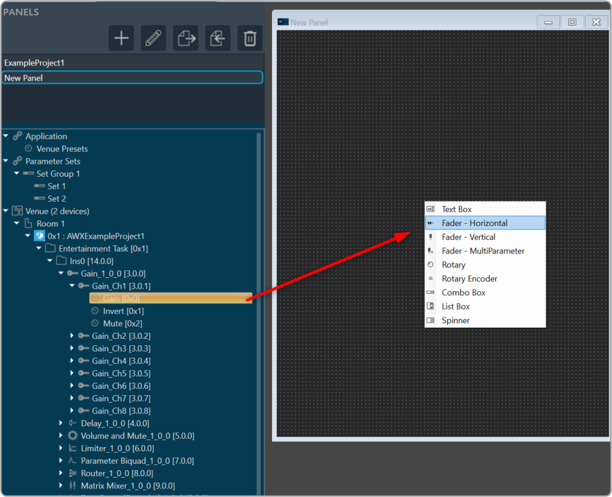
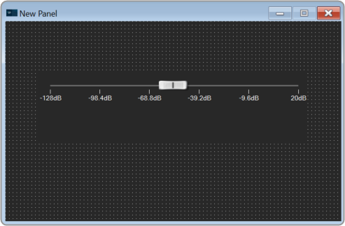
  2. Select the desired control tool from the list to adjust the value. The choice of controls depends on the StateVariable type.
    A screenshot of a computer Description automatically generated

Option 2: Add control and assign StateVariable:

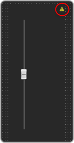
  1. Right-click on the designer workspace Insert > Basic > select the desired control tool from the list to adjust the value.
    A screenshot of a computer Description automatically generated with medium confidence
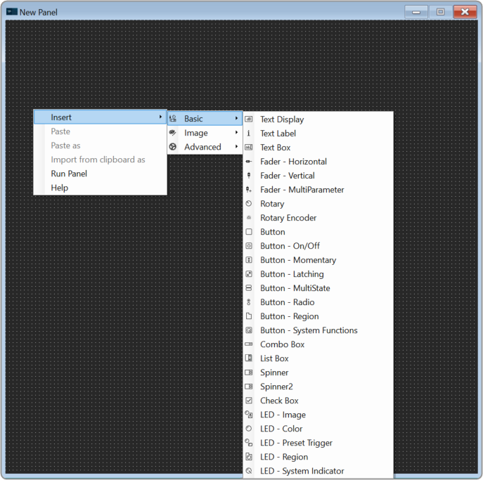
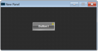
    The control added to the designer workspace. The warning symbol indicates that no StateVariable is assigned to the control.
    A picture containing text, electronics Description automatically generated
  2. Expand the cores of your device and drag-drop a StateVariable on a control. The control value is updated as per StateVariable.

Launch Panel

In order to verify the controls in the panel, you have to launch the control panel.

  1. Select the panel from the Panels view.
  2. Go to Tool panel, and click on Launch Current.

Or Press F5.

Graphical user interface Description automatically generated

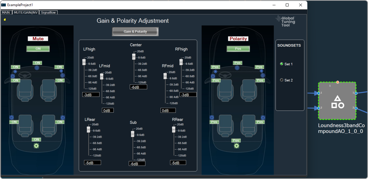
Link Custom Panel with Audio Object

Once a custom panel has been created, it can be linked to any audio object.

  1. Go to device designer tab and open the SFD view of the project.
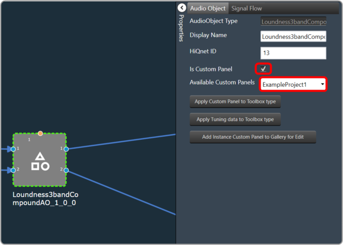
  2. Select the desired audio object and enable the Is Custom Panel option from the Properites view.
  3. Set the required custom panel from the Available Custom Panels list.
    A picture containing graphical user interface Description automatically generated
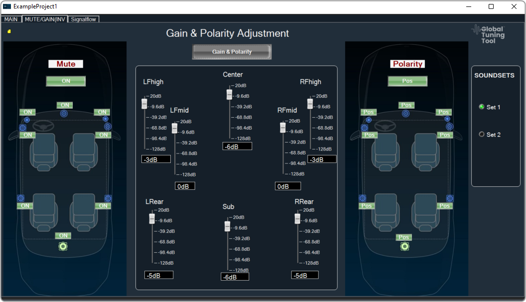
  4. Double-click on the audio object once it has been linked to the custom panel. This will open the custom panel that is assigned to an audio object.
    Graphical user interface Description automatically generated

Change Processing State of Audio Object

This feature allows the user to configure a button to any processing state for a specific object in the custom panel.

  1. Create a new panel and add a Button from the Basic controls tools.
    A screenshot of a computer Description automatically generated with medium confidence
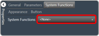
  2. Select the Button, open the Properties view, and select the System Function tab.
  3. Click on System Functions. This opens System Function Editor window.
    Graphical user interface, text, application Description automatically generated
  4. Click on System Function and select Function as Processing state. On the System Function Editor window, select the Function as Processing State from the drop-down list, and Sate as Mute. This opens a Configuration panel.
    Graphical user interface, application Description automatically generated
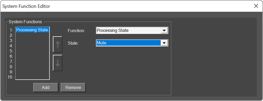
  5. Select the device/project and audio object from the drop-down list which you want to link, and click OK. Depending on the selection of device/project the list of the audio objects is displayed in the drop-down list.
    Graphical user interface, text, application, chat or text message Description automatically generated
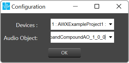
    You can edit the device name and audio object name in the configuration panel.
  6. Click Ok. If you want you can customize the Button appearance.
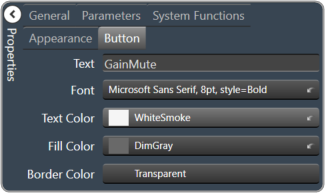
  7. Go to the Properties view, select the Button tab, and change the button name, font style, text color, fill color, and border color.
    Graphical user interface, application Description automatically generated
  8. Click on Launch Current and click on the button to set the processing state

This feature helps you to set the processing state when you don’t have the license to SFD.

« Scale EditorWorking with Parameter Set »
Suggest Edit
  • Careers
  • Contact
  • Sitemap
  • News

© 2025 HARMAN International. All Rights Reserved. Privacy Policy | Cookies | Terms of Use

If you are using a screen reader and are having problems using this website, please call (800) 645-7484 for assistance.