Harman Logo
AUDIOWORX
  • Home
  • Documentation
  • Videos
  • Release Notes
  • Login
Harman Logo
AUDIOWORX
  • Home
  • Documentation
  • Videos
  • Release Notes
  • Login
Harman Logo
AUDIOWORX
  • Home
  • Documentation
  • Videos
  • Release Notes
  • Login
  • Getting Started
  • User Guides
  • Developer Guides

Table of Content

Global Tuning Tool

  1. About Global Tuning Tool
    1. System Requirements
    2. Global Tuning Tool Workflow
  2. Workspace Overview
    1. Home Screen
      1. Home screen Options
      2. Application Options
    2. Device Designer Overview
      1. Tools
      2. Connection
      3. Import and Export
      4. Tuning
      5. Device Panels
    3. Devices and Template View
    4. About Core Objects Toolbox
    5. Device Operations
    6. Properties Panel
    7. Device View
    8. Help
  3. Configurations
    1. Configure State Variable
    2. Configure Default Control-Ids
    3. Configure Preset Controller
      1. Configuring Controller Slot
      2. Core Object Settings
      3. Custom Actions Settings
      4. Exporting Preset Configurations
      5. Maintain Folder Structure
      6. Loading Slots on the Device
      7. Handling Dual Responses
      8. Send Preset Data Online
    4. Link Window
    5. Configure Controller
    6. Launch MIPS Profiling
    7. Launch Memory Profiling
    8. Editing Memory Latency
    9. Configure Streaming and Polling
      1. Start Live Streaming
      2. Record Streaming Data
      3. FFT for Streaming
    10. Configure File controller
    11. Configure Control IDS
    12. Custom Device Usage
    13. Multi-xAF Library Support
    14. Configure External Endpoints
  4. Operations
    1. Create a New Project
    2. Create Signal Flow
    3. Connecting a Device
    4. Routing (Connections)
    5. Device Synchronization
    6. Launching Multiple Signal Flows
    7. Tune a Signal Flow
  5. Designing Custom Panel
    1. Panel Designer Ribbon
      1. Text Design
      2. Fader Design
      3. Rotary Design
      4. Button Design
      5. Box Design
      6. LED Design
      7. Meter Design
      8. Other Design
      9. Images
      10. Advanced
    2. Panels View
    3. Custom Panel Properties View
    4. Designer Workspace
    5. Editor Windows
      1. Parameter Address Editor
      2. Multi-Parameter Address Editor
      3. System Function Editor
      4. State Indication Setup Window
      5. Select Color Window
      6. Discrete Values Editor
      7. Indication Configuration Editor
      8. LED Values Editor
      9. Graph Parameters Window
      10. Scale Editor
    6. Create a Custom Panel in GTT
  6. Working with Parameter Set
    1. Parameter Set Overview
      1. Configuring Parameter Data
      2. Apply Delta in Parameter Sets
      3. Retrieve and Verify Parameter
      4. Import and Export Set File
      5. Preset Comparison
      6. Parameter Sets Explorer Color
      7. Switch Between Multiple Parameter
      8. Saving and Loading Set File
      9. Search in Parameter Sets
    2. Create a Parameter Set in GTT

Signal Flow Designer

  1. Overview Of Signal Flow Designer
  2. Components of Signal Flow Designer
  3. Operations in Signal Flow Designer
    1. Pin Labelling
    2. View Audio Object Metadata
    3. Column Name Configuration Panel
    4. Upgrade Audio Object
    5. Audio Object Processing State
    6. Metering the Signal Flow
    7. Copy and Paste Operation
    8. Undo and Redo Operation
    9. Block Control
    10. Signal Flow Design Validation
    11. Securing Audio Objects
  4. Create a Signal Flow
  5. Tune a Signal Flow
  6. Native Panels
    1. Launching Native Panel
    2. Common Operation in Native Panel
    3. Configuring Custom Native Panels
  7. Additional Audio Parameters
  8. Harman Audio Library Service
  9. Multiple Framework Instances Support
  10. Feedback loop in Signal Flow
  11. Compound Audio Object
    1. Create a Compound Audio Object
    2. Import and Export CAO
    3. Tuning and Editing CAO
    4. Create Preset for CAO
    5. Edit CAO Instance
    6. Set password for CAO
    7. Linking Custom Panel to CAO
    8. Multi dll support for CAO
    9. Delete a Compound Audio Object

Audio Object Description

  1. Audio Object Description Overview
  2. Interface Objects
    1. AudioIO
    2. ControlIn
    3. ControlOut
  3. Basic Objects
    1. Delay
      1. Delay Panel
    2. Gain
      1. Gain Panel
    3. Level Monitor
      1. Level Monitor Panel
    4. FaderBalance
      1. Fader Balance Panel
    5. Volume and Mute
      1. Volume and Mute Panel
    6. VolumeLite
  4. Control Objects
    1. Control Math
    2. Control Grouper
    3. Control GroupSplitter
    4. Control Multi Adder
    5. Control Mixer
      1. Control Mixer Panel
    6. Control Router
      1. Control Router Panel
    7. Control Smooth
    8. AudioToControl
    9. Lookup Table (LUT)
      1. Lookup Table (LUT) Panel
  5. Routing Objects
    1. Router
      1. Router Panel
    2. Splitter
    3. Demux
    4. Selector
  6. Source Objects
    1. Noise Generator
      1. Noise Generator Panel
    2. Wave Generator
    3. FilePlayer
  7. Mixer Objects
    1. Adder
    2. Matrix Mixer
      1. Matrix Mixer Panel
    3. Merger
    4. Fader Matrix
  8. Dynamic Object
    1. Limiter
      1. Limiter Panel
  9. Filter Objects
    1. ParameterBiquad
      1. Parameter Biquad Panel
    2. CoefficientBiquad
      1. Coefficient Biquad Native Panel
    3. Tone Control Extended
      1. Tone Control Extended Panel
    4. XoverBiquad
      1. Xover Biquad Panel
    5. FastConv
      1. Fast Conv Panel
    6. FIR Filter
      1. FIR Filter Panel

Real Time Analyzer

  1. Real Time Analyzer Overview
  2. Real Time Analyzer Components
  3. Settings
    1. Channels Settings
    2. Generator Settings
    3. Analyzer Settings
    4. Microphone Calibration
    5. RTA Advanced Settings
      1. Sound Card Settings
      2. Plugin Host Setting
      3. Advance Analyzer Settings
      4. Advance Generator Settings
      5. Graph Display Settings
      6. Mimo Convolver Settings
      7. Recorder Settings
      8. Routing Settings
    6. Saving and Loading RTA File
  4. Integrated Virtual Process Options
  5. Probe Point Configuration
  6. Real Time Data View
  7. Graph Settings and Measurement
  8. Traces
    1. Trace Toolbar
    2. Trace Configuration
    3. Trace Functionalities
    4. RTA Shortcuts
  9. Analysing Audio Signal

Measurement Module 2.0

  1. Measurement Module Overview
  2. Configurations
    1. Device Output Mapping
    2. Generator
    3. Test Sound
  3. Understand Measurement Process
    1. Scene Setup
    2. Speaker Configuration
    3. Microphone Configuration
    4. Define Measurement
    5. Measurement Session

Central Viewer

  1. Central Viewer Overview
  2. Central Viewer Window
    1. Configurations
    2. Scene Mode
    3. Chart Selector
    4. Waterfall Chart
    5. Graph Area
    6. Curve Lists
    7. Domain Selector
  3. Import Export Central viewer settings

Starter Kit Utility Tool

  1. Starter Kit Utility Tool
  2. Useful Commands for Starter Kit
  3. Starter Kit Troubleshooting
  • Global Tuning Tool
  • Device View

2.7.Device View

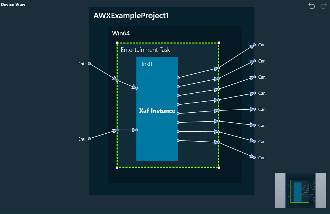
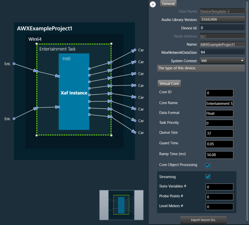
The Device View is used to view and modify detailed information and settings for a specific device. Double-click on the desired device from the list to open a device template in the Device View.

Related Topics

  • Device Object Properties
  • Magnifier Options
  • Undo and Redo Operation

Device Object Properties

A device is a combination of four layers: Device Layer, Physical Layer, Virtual Core Layer, and Core Object Layer. When you select any of the layers, you will see the properties of the selected layer on the right side.

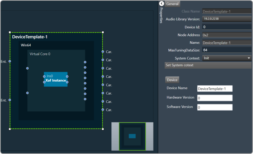
Device Layer: Device layer properties include Device Name, Hardware, and Software version.

Device layer properties are not editable.

Graphical user interface Description automatically generated

Physical Core Layer: Physical Core layer properties include Physical Core Name, Physical Core Type, and MIPS.

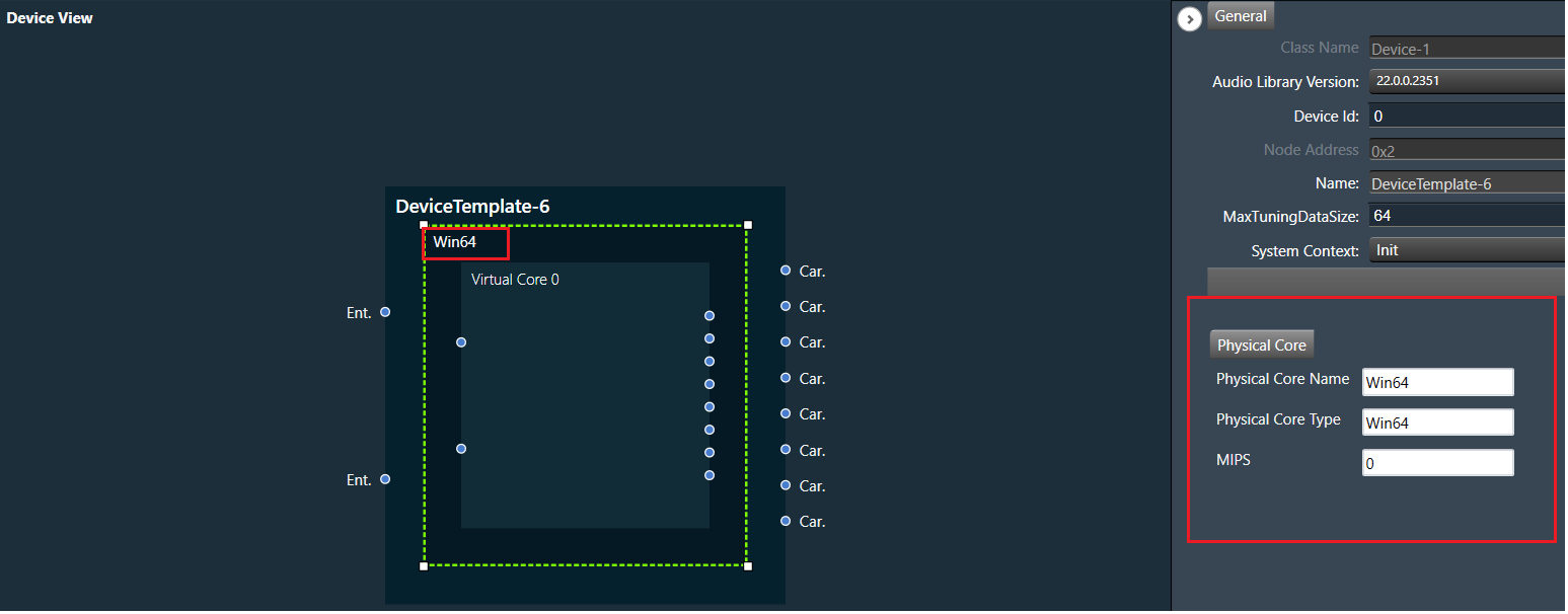
The “Physical Core Name” property in the Physical Core layer properties can be changed, but the “Physical Core Type” and “MIPS” properties are non-editable.

By default, the “Physical Core Name” property value is the same as the “Physical Core Type”. If you want to change the physical core name, enter the value for “Physical Core Name”, the updated Physical Core layer value will be reflected in the device view, then click on the save button to save the changes.

Only from the Device File editor window, you can update the Physical Core Type.

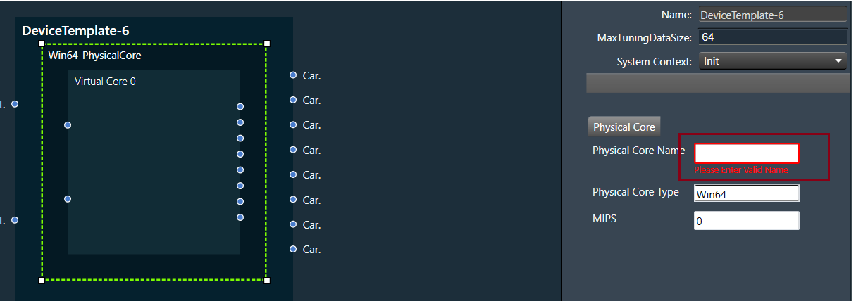
If you keep the Physical Core Name field empty, GTT will ask you to enter the valid name for “Physical Core Name”.

Virtual Core Layer: Virtual Core layer includes the following properties:

  • Core ID: Display the core ID.
  • Core Name: Display the core name.
  • Data Format: Display the date format type.
  • Task Priority: Display the date priority value.
  • Queue Size: Size of message queue
  • Guard Time: Time to avoid message processing as a percentage of interrupt time.
  • Ramp Time (ms): Duration between two processing states (in ms), when the Core Object processing state is enabled.
  • Core Object Processing State: Enable or disable the processing state for Core objects in the core.
  • Streaming: Enable or disable streaming. Enabling the streaming option allows you to set “State Variables”, “Probe Points “, and “Level Meters”.

Queue Size and Guard Time will be supported only for Devices with audio library version “O” release and above or “M+2” release and above.

Enable Core Object Processing State and Ramp Time will be supported only for Devices with audio library version “O” release and above.

Processing state for Core objects will be applied only if Enable Core Object Processing State was enabled before Send Device Configuration.

Enable Probe Points and the Number of Probe Points will be supported only for Devices with audio library version S release and above.

Core Object Layer: Each core object has different properties. For more details refer to the ToolBox.

Magnifier Options

A picture containing graphical user interface Description automatically generated

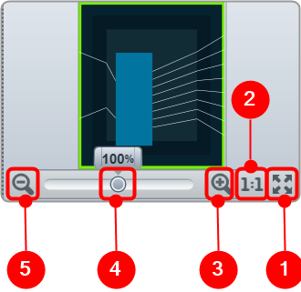
  1. Fit to Window: Click on this button will change the current view to the size of your device view window.
  2. Zoom to 100%: Click on this button will return the view to 100% zoom.
  3. Zoom In: Click on this button (+) to zoom in for gradual increments.
  4. Zoom Slider: Slide to the desired percentage zoom setting.
  5. Zoom Out: Click on this button (-) to zoom out for gradual decrement.

Undo and Redo Operation

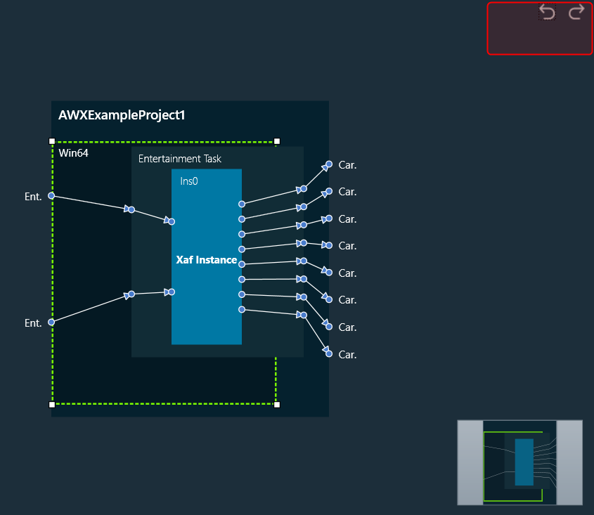
The undo and redo feature allows you to reverse or redo previous actions.

  • Undo: The undo feature allows you to reverse the previous action by restoring the design state to a previous design state.
  • Redo: The redo feature allows you to perform the action that is undone.

Undo/Redo operation is supported for the following actions:

  • Adding/ Removing core objects.
  • Adding, removing, and changing connections.
  • Changing core and core object position.
  • Changing core and core object properties.

The scope of undo/redo is within the selected device.

Undo/redo action will not restore the tuning data state.

This feature is limited to 1000 actions.

When a new manual action (dragging new object, changing connection or position etc) is performed, all existing redo records will be cleared. As a result, it will not be possible to redo any previous actions.

« Properties PanelHelp »
Suggest Edit
  • Careers
  • Contact
  • Sitemap
  • News

© 2025 HARMAN International. All Rights Reserved. Privacy Policy | Cookies | Terms of Use

If you are using a screen reader and are having problems using this website, please call (800) 645-7484 for assistance.