Harman Logo
AUDIOWORX
  • Home
  • Documentation
  • Videos
  • Release Notes
  • Login
Harman Logo
AUDIOWORX
  • Home
  • Documentation
  • Videos
  • Release Notes
  • Login
Harman Logo
AUDIOWORX
  • Home
  • Documentation
  • Videos
  • Release Notes
  • Login
  • Getting Started
  • User Guides
  • Developer Guides

Table of Content

Global Tuning Tool

  1. About Global Tuning Tool
    1. System Requirements
    2. Global Tuning Tool Workflow
  2. Workspace Overview
    1. Home Screen
      1. Home screen Options
      2. Application Options
    2. Device Designer Overview
      1. Tools
      2. Connection
      3. Import and Export
      4. Tuning
      5. Device Panels
    3. Devices and Template View
    4. About Core Objects Toolbox
    5. Device Operations
    6. Properties Panel
    7. Device View
    8. Help
  3. Configurations
    1. Configure State Variable
    2. Configure Default Control-Ids
    3. Configure Preset Controller
      1. Configuring Controller Slot
      2. Core Object Settings
      3. Custom Actions Settings
      4. Exporting Preset Configurations
      5. Maintain Folder Structure
      6. Loading Slots on the Device
      7. Handling Dual Responses
      8. Send Preset Data Online
    4. Link Window
    5. Configure Controller
    6. Launch MIPS Profiling
    7. Launch Memory Profiling
    8. Editing Memory Latency
    9. Configure Streaming and Polling
      1. Start Live Streaming
      2. Record Streaming Data
      3. FFT for Streaming
    10. Configure File controller
    11. Configure Control IDS
    12. Custom Device Usage
    13. Multi-xAF Library Support
    14. Configure External Endpoints
  4. Operations
    1. Create a New Project
    2. Create Signal Flow
    3. Connecting a Device
    4. Routing (Connections)
    5. Device Synchronization
    6. Launching Multiple Signal Flows
    7. Tune a Signal Flow
  5. Designing Custom Panel
    1. Panel Designer Ribbon
      1. Text Design
      2. Fader Design
      3. Rotary Design
      4. Button Design
      5. Box Design
      6. LED Design
      7. Meter Design
      8. Other Design
      9. Images
      10. Advanced
    2. Panels View
    3. Custom Panel Properties View
    4. Designer Workspace
    5. Editor Windows
      1. Parameter Address Editor
      2. Multi-Parameter Address Editor
      3. System Function Editor
      4. State Indication Setup Window
      5. Select Color Window
      6. Discrete Values Editor
      7. Indication Configuration Editor
      8. LED Values Editor
      9. Graph Parameters Window
      10. Scale Editor
    6. Create a Custom Panel in GTT
  6. Working with Parameter Set
    1. Parameter Set Overview
      1. Configuring Parameter Data
      2. Apply Delta in Parameter Sets
      3. Retrieve and Verify Parameter
      4. Import and Export Set File
      5. Preset Comparison
      6. Parameter Sets Explorer Color
      7. Switch Between Multiple Parameter
      8. Saving and Loading Set File
      9. Search in Parameter Sets
    2. Create a Parameter Set in GTT

Signal Flow Designer

  1. Overview Of Signal Flow Designer
  2. Components of Signal Flow Designer
  3. Operations in Signal Flow Designer
    1. Pin Labelling
    2. View Audio Object Metadata
    3. Column Name Configuration Panel
    4. Upgrade Audio Object
    5. Audio Object Processing State
    6. Metering the Signal Flow
    7. Copy and Paste Operation
    8. Undo and Redo Operation
    9. Block Control
    10. Signal Flow Design Validation
    11. Securing Audio Objects
  4. Create a Signal Flow
  5. Tune a Signal Flow
  6. Native Panels
    1. Launching Native Panel
    2. Common Operation in Native Panel
    3. Configuring Custom Native Panels
  7. Additional Audio Parameters
  8. Harman Audio Library Service
  9. Multiple Framework Instances Support
  10. Feedback loop in Signal Flow
  11. Compound Audio Object
    1. Create a Compound Audio Object
    2. Import and Export CAO
    3. Tuning and Editing CAO
    4. Create Preset for CAO
    5. Edit CAO Instance
    6. Set password for CAO
    7. Linking Custom Panel to CAO
    8. Multi dll support for CAO
    9. Delete a Compound Audio Object

Audio Object Description

  1. Audio Object Description Overview
  2. Interface Objects
    1. AudioIO
    2. ControlIn
    3. ControlOut
  3. Basic Objects
    1. Delay
      1. Delay Panel
    2. Gain
      1. Gain Panel
    3. Level Monitor
      1. Level Monitor Panel
    4. FaderBalance
      1. Fader Balance Panel
    5. Volume and Mute
      1. Volume and Mute Panel
    6. VolumeLite
  4. Control Objects
    1. Control Math
    2. Control Grouper
    3. Control GroupSplitter
    4. Control Multi Adder
    5. Control Mixer
      1. Control Mixer Panel
    6. Control Router
      1. Control Router Panel
    7. Control Smooth
    8. AudioToControl
    9. Lookup Table (LUT)
      1. Lookup Table (LUT) Panel
  5. Routing Objects
    1. Router
      1. Router Panel
    2. Splitter
    3. Demux
    4. Selector
  6. Source Objects
    1. Noise Generator
      1. Noise Generator Panel
    2. Wave Generator
    3. FilePlayer
  7. Mixer Objects
    1. Adder
    2. Matrix Mixer
      1. Matrix Mixer Panel
    3. Merger
    4. Fader Matrix
  8. Dynamic Object
    1. Limiter
      1. Limiter Panel
  9. Filter Objects
    1. ParameterBiquad
      1. Parameter Biquad Panel
    2. CoefficientBiquad
      1. Coefficient Biquad Native Panel
    3. Tone Control Extended
      1. Tone Control Extended Panel
    4. XoverBiquad
      1. Xover Biquad Panel
    5. FastConv
      1. Fast Conv Panel
    6. FIR Filter
      1. FIR Filter Panel

Real Time Analyzer

  1. Real Time Analyzer Overview
  2. Real Time Analyzer Components
  3. Settings
    1. Channels Settings
    2. Generator Settings
    3. Analyzer Settings
    4. Microphone Calibration
    5. RTA Advanced Settings
      1. Sound Card Settings
      2. Plugin Host Setting
      3. Advance Analyzer Settings
      4. Advance Generator Settings
      5. Graph Display Settings
      6. Mimo Convolver Settings
      7. Recorder Settings
      8. Routing Settings
    6. Saving and Loading RTA File
  4. Integrated Virtual Process Options
  5. Probe Point Configuration
  6. Real Time Data View
  7. Graph Settings and Measurement
  8. Traces
    1. Trace Toolbar
    2. Trace Configuration
    3. Trace Functionalities
    4. RTA Shortcuts
  9. Analysing Audio Signal

Measurement Module 2.0

  1. Measurement Module Overview
  2. Configurations
    1. Device Output Mapping
    2. Generator
    3. Test Sound
  3. Understand Measurement Process
    1. Scene Setup
    2. Speaker Configuration
    3. Microphone Configuration
    4. Define Measurement
    5. Measurement Session

Central Viewer

  1. Central Viewer Overview
  2. Central Viewer Window
    1. Configurations
    2. Scene Mode
    3. Chart Selector
    4. Waterfall Chart
    5. Graph Area
    6. Curve Lists
    7. Domain Selector
  3. Import Export Central viewer settings

Starter Kit Utility Tool

  1. Starter Kit Utility Tool
  2. Useful Commands for Starter Kit
  3. Starter Kit Troubleshooting
  • Global Tuning Tool
  • Exporting Preset Configurations

3.3.4.Exporting Preset Configurations

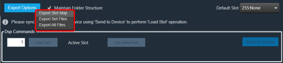
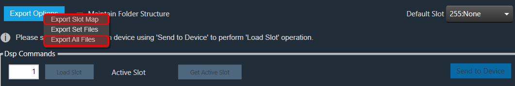
You can export Preset Configuration using following methods:

  • Export Slot Map: To save the flash files of the slot map in the selected path.
  • Export Set Files: To save all the set files of the map in the selected path.
  • Export All Files: To save all the set files of the map along with the flash file in the selected path.

Right-click or click on “Export Options” to select the type of export.

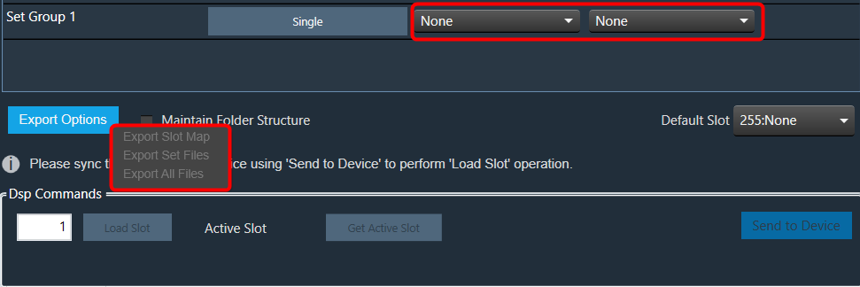
To export a slot map set files all files should contain at least one valid slot, otherwise the options Export Slot Map, Export Set Files, Export All Files, and Export Slot will be disabled.

Exporting human readable flash file: The exported flash file is useful in the event any slot got accidentally deleted. You can reconfigured Preset Controller values using the slot map table details mentioned the exported flash file.

Once you have configured all parameters of the Preset Controllers , it is recommended that you export the flash file.

Steps to export human readable flash file:

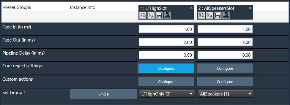
  1. Open Preset Controller, add and configure the slots.
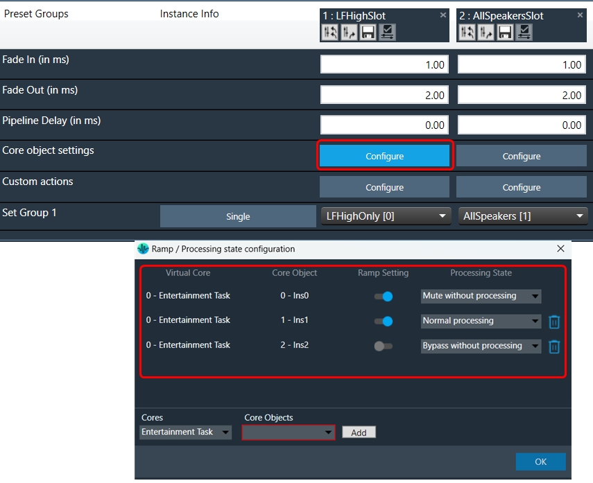
  2. Click on the Configure and enable or disable “Ramp Setting”.
  3. Click on Export Slot Map or Export All Files, browse the desire location, enter the file name, and click Save.

    This action creates two files, one human-readable CSV file and another flash file at the specified path.
    The name of the CSV file is determined by the name of the flash file, which is the original file.
    Example: The flash file name in the example below is Map.flash, so the readable CSV created file name is Map.flashr.
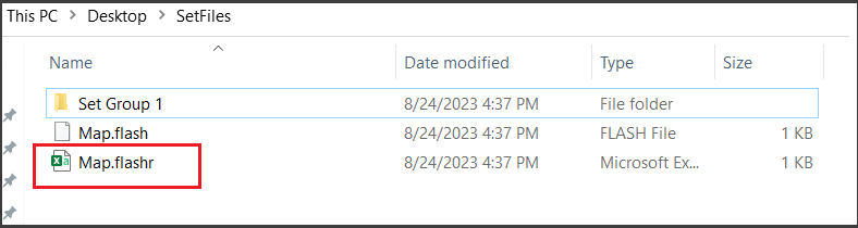
  4. Open the CSV file to see the slot details.
    In the below image, the Ramp Setting details for “1: Core 0” column is “0:0 Disabled 1:0 Enabled 1:1 Enabled”, which is “Core Id : Instance ID : State” .

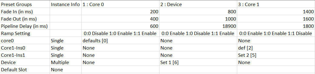
    The below image explains the “Ramp Setting” configuration for “0:0 Enabled 0:1 Enabled 0:1 Disabled” in the GTT.
    Similarly, all ramp settings detail will be exported in this format.
« Custom Actions SettingsMaintain Folder Structure »
Suggest Edit
  • Careers
  • Contact
  • Sitemap
  • News

© 2025 HARMAN International. All Rights Reserved. Privacy Policy | Cookies | Terms of Use

If you are using a screen reader and are having problems using this website, please call (800) 645-7484 for assistance.