Table of Content

Meter Design
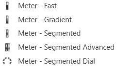
Meter Fast
A Fast Meter is an output meter that shows the state of a device parameter. Controls can be managed in the Custom Panel designer and, once the Custom Panel is activated, utilized by the end user. This control must be linked to a parameter to function properly.
Meter Gradient
A gradient meter is an output meter that shows the state of a device parameter in specifically designed gradients. Controls can be managed in the Custom Panel designer and, once the Custom Panel is activated, utilized by the end user. This control must be linked to a parameter to function properly.
Meter Segmented
A segmented meter is an output meter that shows the state of a device parameter.Controls can be managed in the Custom Panel designer and, once the Custom Panel is activated, utilized by the end user. This control must be linked to a parameter to function properly.
Meter Segmented Advanced
A segmented advanced meter is an output meter that shows the state of a device parameter.Controls can be managed in the Custom Panel designer and, once the Custom Panel is activated, utilized by the end user. This control must be linked to a parameter to function properly.
Meter Segmented Dial
A segmented dial meter is an output meter that shows the state of a device parameter.Controls can be managed in the Custom Panel designer and, once the Custom Panel is activated, utilized by the end user. This control must be linked to a parameter to function properly.
Common Roter Design Properties
| Properties Type |
Description |
| General |
|
| Parameters |
|
| Appearance |
This decreases the aesthetic properties of the meter. |
| Meter |
|
| Scale |
|