Table of Content


Saving and Loading Set File
Saving Parameter Sets
When a device is removed or GTT is closed, parameter sets are automatically saved.
There is currently a limitation on saving parameter sets to databases.
The parameter set is not immediately saved to the database. It is saved in the moment when the device is removed from the device list. Therefore, if the signal flow is modified (for which there is an associated parameter set) when the device is not in device list, the old parameter sets are retrieved from the database when the device is dragged to device list next time.
Different Methods for Saving Set Files
Saving Set File from Device
- Navigate to the Device Designer tab and choose the desired device for storing the set file.
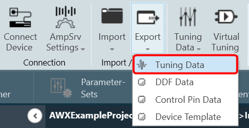
- Click on Export > Tuning Data.
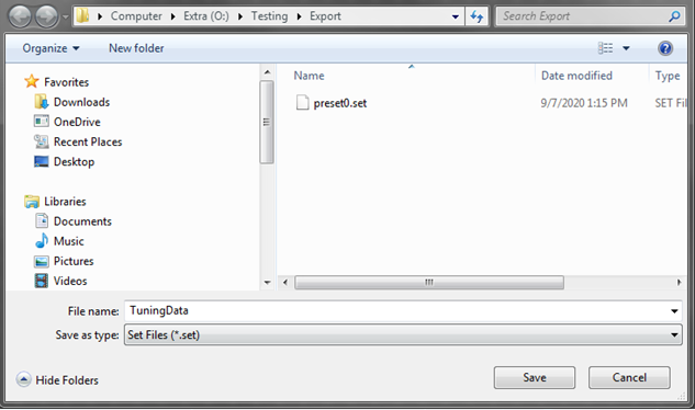
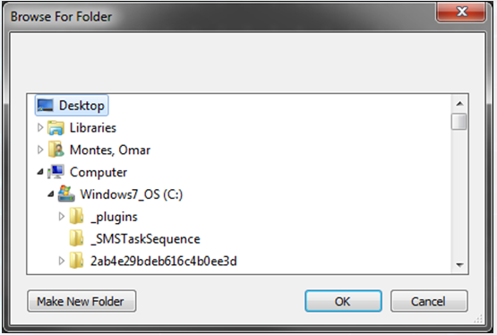
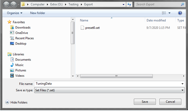
- A dialog box will be displayed, select the folder where the files (.set/.setr) will be stored, type a file name, and click on Save.
Saving Set File from Presets
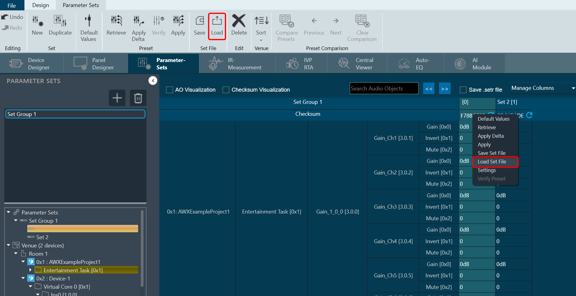
- Navigate to the Parameter Sets tab and choose the desired Set column.
- Right-click on the chosen Set column to open the context menu and select Save Set File.

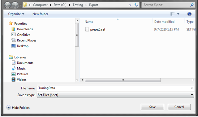
A dialog box will appear, where you can choose the folder to store the files (.set/.setr). Enter a file name and click on the Save button.
Saving Set File from Preset Controller
- Navigate to the Device Designer tab and click on Preset Controller. This opens Preset Controller window will be opened.
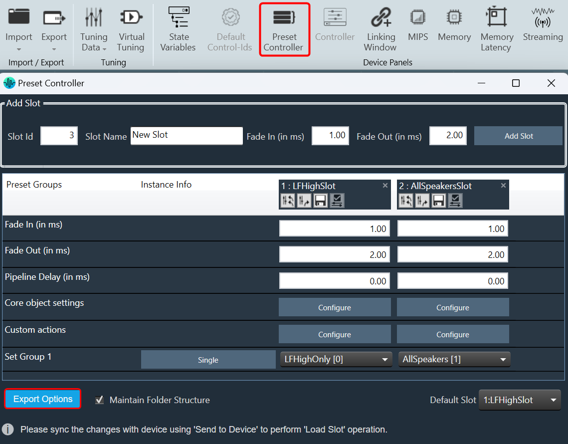
- In the Preset Controller window, right-click on Export Options and click on Export Set Files.
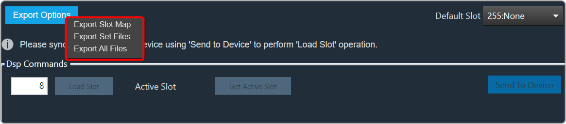
A dialog box will appear, where you can choose the folder to store the files (.set/.setr). Enter a file name and click on the Save button.
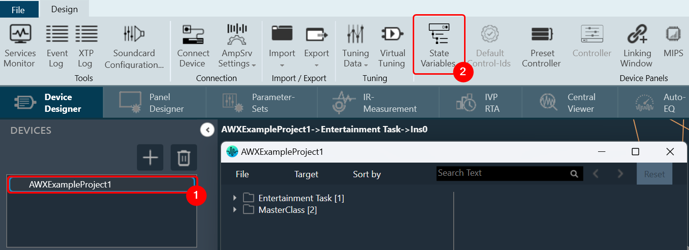
Saving Set File from State Variables Explorer
- Navigate to the Device Designer tab and select the device from which you would like to select and store the set file.
- Click on State Variables. This opens the State Variables window.
- On the State Variable window, select from File and click Save Set As.
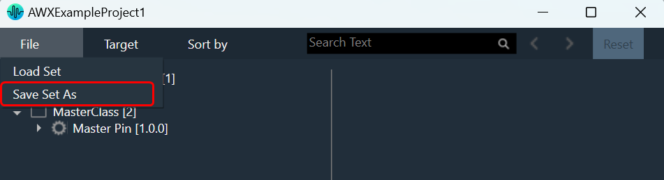
A dialog box will appear, where you can choose the folder to store the files (.set/.setr). Enter a file name and click on the Save button.
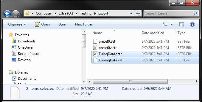
Once you have saved the set file, both the .set and .setr files will be accessible in the folder you selected.
If the set file is generated using a different panel, such as the IESS panel, the .setr file will not be generated by default. However, you can utilize any of the methods mentioned earlier to generate the .setr file if needed.
Loading a Set File
In the context menu of any set Click on “Load Set file”. This opens a dialog to select the .set file to be loaded. On selecting the .set file, tuning data will be loaded on to the selected set. On clicking Undo, load action will be undone and old preset values will be displayed in the screen.
Only matching (CoreId, InstanceId, BlockId, and SublockId) object’s tuning data will be loaded.
Notifications to the user during load:
- If there are additional objects in .set file than set group a notification message will be displayed.
- If there are additional objects in set group than in .set file a notification message will be displayed.
- If there is a mismatch in the size of the AO a notification message will be displayed.
- If there are mismatching objects in both .set file and set group, a notification message will be displayed.
All the mismatched object details will be displayed in event log.
Tuning data will be loaded only on to the set in the parameter set column. Not on to the state variables.