Harman Logo
AUDIOWORX
  • Home
  • Documentation
  • Videos
  • Release Notes
  • Login
Harman Logo
AUDIOWORX
  • Home
  • Documentation
  • Videos
  • Release Notes
  • Login
Harman Logo
AUDIOWORX
  • Home
  • Documentation
  • Videos
  • Release Notes
  • Login
  • Getting Started
  • User Guides
  • Developer Guides

Table of Content

Global Tuning Tool

  1. About Global Tuning Tool
    1. System Requirements
    2. Global Tuning Tool Workflow
  2. Workspace Overview
    1. Home Screen
      1. Home screen Options
      2. Application Options
    2. Device Designer Overview
      1. Tools
      2. Connection
      3. Import and Export
      4. Tuning
      5. Device Panels
    3. Devices and Template View
    4. About Core Objects Toolbox
    5. Device Operations
    6. Properties Panel
    7. Device View
    8. Help
  3. Configurations
    1. Configure State Variable
    2. Configure Default Control-Ids
    3. Configure Preset Controller
      1. Configuring Controller Slot
      2. Core Object Settings
      3. Custom Actions Settings
      4. Exporting Preset Configurations
      5. Maintain Folder Structure
      6. Loading Slots on the Device
      7. Handling Dual Responses
      8. Send Preset Data Online
    4. Link Window
    5. Configure Controller
    6. Launch MIPS Profiling
    7. Launch Memory Profiling
    8. Editing Memory Latency
    9. Configure Streaming and Polling
      1. Start Live Streaming
      2. Record Streaming Data
      3. FFT for Streaming
    10. Configure File controller
    11. Configure Control IDS
    12. Custom Device Usage
    13. Multi-xAF Library Support
    14. Configure External Endpoints
  4. Operations
    1. Create a New Project
    2. Create Signal Flow
    3. Connecting a Device
    4. Routing (Connections)
    5. Device Synchronization
    6. Launching Multiple Signal Flows
    7. Tune a Signal Flow
  5. Designing Custom Panel
    1. Panel Designer Ribbon
      1. Text Design
      2. Fader Design
      3. Rotary Design
      4. Button Design
      5. Box Design
      6. LED Design
      7. Meter Design
      8. Other Design
      9. Images
      10. Advanced
    2. Panels View
    3. Custom Panel Properties View
    4. Designer Workspace
    5. Editor Windows
      1. Parameter Address Editor
      2. Multi-Parameter Address Editor
      3. System Function Editor
      4. State Indication Setup Window
      5. Select Color Window
      6. Discrete Values Editor
      7. Indication Configuration Editor
      8. LED Values Editor
      9. Graph Parameters Window
      10. Scale Editor
    6. Create a Custom Panel in GTT
  6. Working with Parameter Set
    1. Parameter Set Overview
      1. Configuring Parameter Data
      2. Apply Delta in Parameter Sets
      3. Retrieve and Verify Parameter
      4. Import and Export Set File
      5. Preset Comparison
      6. Parameter Sets Explorer Color
      7. Switch Between Multiple Parameter
      8. Saving and Loading Set File
      9. Search in Parameter Sets
    2. Create a Parameter Set in GTT

Signal Flow Designer

  1. Overview Of Signal Flow Designer
  2. Components of Signal Flow Designer
  3. Operations in Signal Flow Designer
    1. Pin Labelling
    2. View Audio Object Metadata
    3. Column Name Configuration Panel
    4. Upgrade Audio Object
    5. Audio Object Processing State
    6. Metering the Signal Flow
    7. Copy and Paste Operation
    8. Undo and Redo Operation
    9. Block Control
    10. Signal Flow Design Validation
    11. Securing Audio Objects
  4. Create a Signal Flow
  5. Tune a Signal Flow
  6. Native Panels
    1. Launching Native Panel
    2. Common Operation in Native Panel
    3. Configuring Custom Native Panels
  7. Additional Audio Parameters
  8. Harman Audio Library Service
  9. Multiple Framework Instances Support
  10. Feedback loop in Signal Flow
  11. Compound Audio Object
    1. Create a Compound Audio Object
    2. Import and Export CAO
    3. Tuning and Editing CAO
    4. Create Preset for CAO
    5. Edit CAO Instance
    6. Set password for CAO
    7. Linking Custom Panel to CAO
    8. Multi dll support for CAO
    9. Delete a Compound Audio Object

Audio Object Description

  1. Audio Object Description Overview
  2. Interface Objects
    1. AudioIO
    2. ControlIn
    3. ControlOut
  3. Basic Objects
    1. Delay
      1. Delay Panel
    2. Gain
      1. Gain Panel
    3. Level Monitor
      1. Level Monitor Panel
    4. FaderBalance
      1. Fader Balance Panel
    5. Volume and Mute
      1. Volume and Mute Panel
    6. VolumeLite
  4. Control Objects
    1. Control Math
    2. Control Grouper
    3. Control GroupSplitter
    4. Control Multi Adder
    5. Control Mixer
      1. Control Mixer Panel
    6. Control Router
      1. Control Router Panel
    7. Control Smooth
    8. AudioToControl
    9. Lookup Table (LUT)
      1. Lookup Table (LUT) Panel
  5. Routing Objects
    1. Router
      1. Router Panel
    2. Splitter
    3. Demux
    4. Selector
  6. Source Objects
    1. Noise Generator
      1. Noise Generator Panel
    2. Wave Generator
    3. FilePlayer
  7. Mixer Objects
    1. Adder
    2. Matrix Mixer
      1. Matrix Mixer Panel
    3. Merger
    4. Fader Matrix
  8. Dynamic Object
    1. Limiter
      1. Limiter Panel
  9. Filter Objects
    1. ParameterBiquad
      1. Parameter Biquad Panel
    2. CoefficientBiquad
      1. Coefficient Biquad Native Panel
    3. Tone Control Extended
      1. Tone Control Extended Panel
    4. XoverBiquad
      1. Xover Biquad Panel
    5. FastConv
      1. Fast Conv Panel
    6. FIR Filter
      1. FIR Filter Panel

Real Time Analyzer

  1. Real Time Analyzer Overview
  2. Real Time Analyzer Components
  3. Settings
    1. Channels Settings
    2. Generator Settings
    3. Analyzer Settings
    4. Microphone Calibration
    5. RTA Advanced Settings
      1. Sound Card Settings
      2. Plugin Host Setting
      3. Advance Analyzer Settings
      4. Advance Generator Settings
      5. Graph Display Settings
      6. Mimo Convolver Settings
      7. Recorder Settings
      8. Routing Settings
    6. Saving and Loading RTA File
  4. Integrated Virtual Process Options
  5. Probe Point Configuration
  6. Real Time Data View
  7. Graph Settings and Measurement
  8. Traces
    1. Trace Toolbar
    2. Trace Configuration
    3. Trace Functionalities
    4. RTA Shortcuts
  9. Analysing Audio Signal

Measurement Module 2.0

  1. Measurement Module Overview
  2. Configurations
    1. Device Output Mapping
    2. Generator
    3. Test Sound
  3. Understand Measurement Process
    1. Scene Setup
    2. Speaker Configuration
    3. Microphone Configuration
    4. Define Measurement
    5. Measurement Session

Central Viewer

  1. Central Viewer Overview
  2. Central Viewer Window
    1. Configurations
    2. Scene Mode
    3. Chart Selector
    4. Waterfall Chart
    5. Graph Area
    6. Curve Lists
    7. Domain Selector
  3. Import Export Central viewer settings

Starter Kit Utility Tool

  1. Starter Kit Utility Tool
  2. Useful Commands for Starter Kit
  3. Starter Kit Troubleshooting
  • Global Tuning Tool
  • Start Live Streaming

3.9.1.Start Live Streaming

Ensure that the following requirements are met before beginning the streaming process.

  • Make sure the device is connected to GTT.
  • If you want to stream streamable state variable, then you can enable Streaming option, for more details refer Streaming.
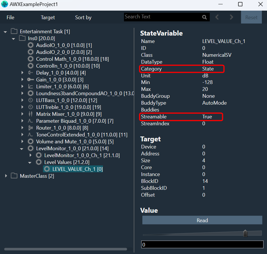
  • While performing streaming make sure the parameter supports streaming. You can verify this by opening the state variable explorer and confirming that the “Category” is set to “state” and “Streamable” is set to “true” for the parameter.

To start live streaming, follow the below steps:

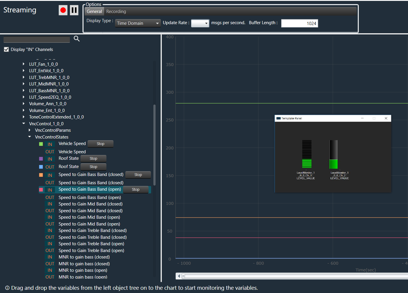
  1. Open GTT project, click on the Streaming option from the Device Designer tab. This opens the streaming window.
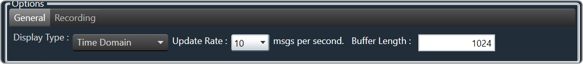
  2. On the General option, set the Display Type, Update Rate, and Buffer Length.
    The Update Rate will be applied to all live streams, and Buffer length (the maximum streaming data that can be stored) can be changed any time during the live streaming.
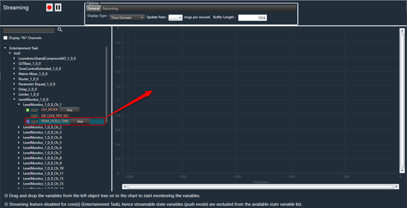
  3. Expand the state variable you want to stream and drag-drop the variable from the object tree to graph. This starts live streaming of the variable.
    Active streams can be matched with the curve on graph by the colors of the curve and the rectangular block next to the state variable.

    The graph can be zoomed on both the x and y axes by scrolling.
  4. Click on the Stop option, if you want to stop streaming of the variable.

You can open multiple streaming windows for a device and stream on multiple devices. However state variable can be streamed in only one window at a time and not in multiple window.

If the “Streaming” feature is disabled for any core, streamable state variables (push mode) will be excluded from the available state variable list for that core.

Viewing Streaming Data in Custom Panel

You can view live streaming data in a custom panel. Map the streaming state variable address to any control on the custom panel and start the live streaming from the streaming window. Then, launch the custom control panel.

The live streaming of the state variable will be displayed on a custom panel.
Only the current value of the state variable will be displayed on the custom panel.
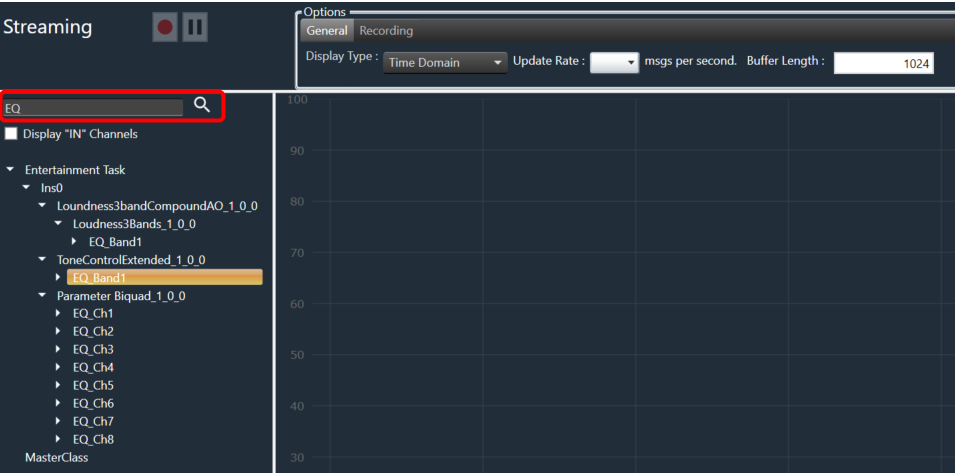
Search Variable

You can search for a specific variable from the object tree in the Streaming window and then drag and drop it onto the chart.

To find a variable in the Streaming window, enter at least two keywords of the variable in the search bar. The GTT will use these keywords to search and display the filter results in the object tree.
A screenshot of a computer Description automatically generated with medium confidence

Limitations in Streaming

Below are the limitations associated with streaming.

  • Last selected update rate will be applied to all active streams.
  • The update rate is not configurable, you need to select one of the predefined values from the drop-down menu. It is not possible to enter a custom update rate.
  • Maximum buffer length allowed is 65536.
  • Streaming state variables are read only.
  • Zooming the graph with more than 8 active streams in parallel may cause performance issues.

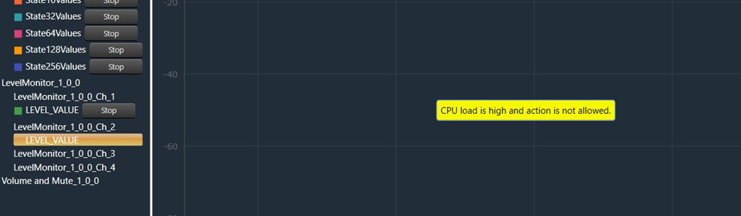
Opening multiple streaming windows may result in increased CPU load, potentially leading to performance issues. To avoid such concerns, you can configure the option to receive notifications and restrict streaming when CPU load exceeds a certain threshold.
By default, the maximum allowed CPU load is set to 100%. However, you can configure restrictions at specific load levels by modifying the “MaxAllowedCpuLoadForMonitoring” value in the configuration file.

« Configure Streaming and PollingRecord Streaming Data »
Suggest Edit
  • Careers
  • Contact
  • Sitemap
  • News

© 2025 HARMAN International. All Rights Reserved. Privacy Policy | Cookies | Terms of Use

If you are using a screen reader and are having problems using this website, please call (800) 645-7484 for assistance.