Harman Logo
AUDIOWORX
  • Home
  • Documentation
  • Videos
  • Release Notes
  • Login
Harman Logo
AUDIOWORX
  • Home
  • Documentation
  • Videos
  • Release Notes
  • Login
Harman Logo
AUDIOWORX
  • Home
  • Documentation
  • Videos
  • Release Notes
  • Login
  • Getting Started
  • User Guides
  • Developer Guides

Table of Content

Global Tuning Tool

  1. About Global Tuning Tool
    1. System Requirements
    2. Global Tuning Tool Workflow
  2. Workspace Overview
    1. Home Screen
      1. Home screen Options
      2. Application Options
    2. Device Designer Overview
      1. Tools
      2. Connection
      3. Import and Export
      4. Tuning
      5. Device Panels
    3. Devices and Template View
    4. About Core Objects Toolbox
    5. Device Operations
    6. Properties Panel
    7. Device View
    8. Help
  3. Configurations
    1. Configure State Variable
    2. Configure Default Control-Ids
    3. Configure Preset Controller
      1. Configuring Controller Slot
      2. Core Object Settings
      3. Custom Actions Settings
      4. Exporting Preset Configurations
      5. Maintain Folder Structure
      6. Loading Slots on the Device
      7. Handling Dual Responses
      8. Send Preset Data Online
    4. Link Window
    5. Configure Controller
    6. Launch MIPS Profiling
    7. Launch Memory Profiling
    8. Editing Memory Latency
    9. Configure Streaming and Polling
      1. Start Live Streaming
      2. Record Streaming Data
      3. FFT for Streaming
    10. Configure File controller
    11. Configure Control IDS
    12. Custom Device Usage
    13. Multi-xAF Library Support
    14. Configure External Endpoints
  4. Operations
    1. Create a New Project
    2. Create Signal Flow
    3. Connecting a Device
    4. Routing (Connections)
    5. Device Synchronization
    6. Launching Multiple Signal Flows
    7. Tune a Signal Flow
  5. Designing Custom Panel
    1. Panel Designer Ribbon
      1. Text Design
      2. Fader Design
      3. Rotary Design
      4. Button Design
      5. Box Design
      6. LED Design
      7. Meter Design
      8. Other Design
      9. Images
      10. Advanced
    2. Panels View
    3. Custom Panel Properties View
    4. Designer Workspace
    5. Editor Windows
      1. Parameter Address Editor
      2. Multi-Parameter Address Editor
      3. System Function Editor
      4. State Indication Setup Window
      5. Select Color Window
      6. Discrete Values Editor
      7. Indication Configuration Editor
      8. LED Values Editor
      9. Graph Parameters Window
      10. Scale Editor
    6. Create a Custom Panel in GTT
  6. Working with Parameter Set
    1. Parameter Set Overview
      1. Configuring Parameter Data
      2. Apply Delta in Parameter Sets
      3. Retrieve and Verify Parameter
      4. Import and Export Set File
      5. Preset Comparison
      6. Parameter Sets Explorer Color
      7. Switch Between Multiple Parameter
      8. Saving and Loading Set File
      9. Search in Parameter Sets
    2. Create a Parameter Set in GTT

Signal Flow Designer

  1. Overview Of Signal Flow Designer
  2. Components of Signal Flow Designer
  3. Operations in Signal Flow Designer
    1. Pin Labelling
    2. View Audio Object Metadata
    3. Column Name Configuration Panel
    4. Upgrade Audio Object
    5. Audio Object Processing State
    6. Metering the Signal Flow
    7. Copy and Paste Operation
    8. Undo and Redo Operation
    9. Block Control
    10. Signal Flow Design Validation
    11. Securing Audio Objects
  4. Create a Signal Flow
  5. Tune a Signal Flow
  6. Native Panels
    1. Launching Native Panel
    2. Common Operation in Native Panel
    3. Configuring Custom Native Panels
  7. Additional Audio Parameters
  8. Harman Audio Library Service
  9. Multiple Framework Instances Support
  10. Feedback loop in Signal Flow
  11. Compound Audio Object
    1. Create a Compound Audio Object
    2. Import and Export CAO
    3. Tuning and Editing CAO
    4. Create Preset for CAO
    5. Edit CAO Instance
    6. Set password for CAO
    7. Linking Custom Panel to CAO
    8. Multi dll support for CAO
    9. Delete a Compound Audio Object

Audio Object Description

  1. Audio Object Description Overview
  2. Interface Objects
    1. AudioIO
    2. ControlIn
    3. ControlOut
  3. Basic Objects
    1. Delay
      1. Delay Panel
    2. Gain
      1. Gain Panel
    3. Level Monitor
      1. Level Monitor Panel
    4. FaderBalance
      1. Fader Balance Panel
    5. Volume and Mute
      1. Volume and Mute Panel
    6. VolumeLite
  4. Control Objects
    1. Control Math
    2. Control Grouper
    3. Control GroupSplitter
    4. Control Multi Adder
    5. Control Mixer
      1. Control Mixer Panel
    6. Control Router
      1. Control Router Panel
    7. Control Smooth
    8. AudioToControl
    9. Lookup Table (LUT)
      1. Lookup Table (LUT) Panel
  5. Routing Objects
    1. Router
      1. Router Panel
    2. Splitter
    3. Demux
    4. Selector
  6. Source Objects
    1. Noise Generator
      1. Noise Generator Panel
    2. Wave Generator
    3. FilePlayer
  7. Mixer Objects
    1. Adder
    2. Matrix Mixer
      1. Matrix Mixer Panel
    3. Merger
    4. Fader Matrix
  8. Dynamic Object
    1. Limiter
      1. Limiter Panel
  9. Filter Objects
    1. ParameterBiquad
      1. Parameter Biquad Panel
    2. CoefficientBiquad
      1. Coefficient Biquad Native Panel
    3. Tone Control Extended
      1. Tone Control Extended Panel
    4. XoverBiquad
      1. Xover Biquad Panel
    5. FastConv
      1. Fast Conv Panel
    6. FIR Filter
      1. FIR Filter Panel

Real Time Analyzer

  1. Real Time Analyzer Overview
  2. Real Time Analyzer Components
  3. Settings
    1. Channels Settings
    2. Generator Settings
    3. Analyzer Settings
    4. Microphone Calibration
    5. RTA Advanced Settings
      1. Sound Card Settings
      2. Plugin Host Setting
      3. Advance Analyzer Settings
      4. Advance Generator Settings
      5. Graph Display Settings
      6. Mimo Convolver Settings
      7. Recorder Settings
      8. Routing Settings
    6. Saving and Loading RTA File
  4. Integrated Virtual Process Options
  5. Probe Point Configuration
  6. Real Time Data View
  7. Graph Settings and Measurement
  8. Traces
    1. Trace Toolbar
    2. Trace Configuration
    3. Trace Functionalities
    4. RTA Shortcuts
  9. Analysing Audio Signal

Measurement Module 2.0

  1. Measurement Module Overview
  2. Configurations
    1. Device Output Mapping
    2. Generator
    3. Test Sound
  3. Understand Measurement Process
    1. Scene Setup
    2. Speaker Configuration
    3. Microphone Configuration
    4. Define Measurement
    5. Measurement Session

Central Viewer

  1. Central Viewer Overview
  2. Central Viewer Window
    1. Configurations
    2. Scene Mode
    3. Chart Selector
    4. Waterfall Chart
    5. Graph Area
    6. Curve Lists
    7. Domain Selector
  3. Import Export Central viewer settings

Starter Kit Utility Tool

  1. Starter Kit Utility Tool
  2. Useful Commands for Starter Kit
  3. Starter Kit Troubleshooting
  • Global Tuning Tool
  • Tuning

2.2.4.Tuning

Tuning Data

You need to connect a device to GTT to send/receive tuning or state data.

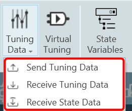
When the device is connected you will get the following options.

  • Send Tuning Data
  • Receive Tuning Data
  • Receive State Data

Virtual Tuning

This feature will be removed in the future Global Tuning Tool release.

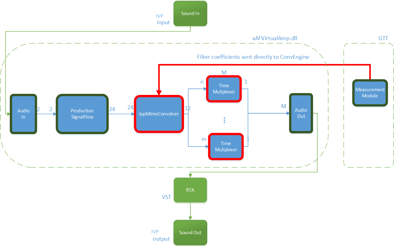
Virtual Tuning allows you to measure impulse responses of an acoustic environment using the AudioworX Measurement Module. Based on these measurements, a production signal flow can be virtually tuned.

For this purpose, two new audio objects are implemented in AudioworX:

  • IppMimoConvolver
  • Time Multiplexer

IppMimoConvolver: The IppMimoConvolver audio object provides MIMO convolution with FIR filters using the Intel Integrated Performance Primitives (IPP) library, a multi-threaded software library of multimedia and data processing applications. It is highly optimized for various Intel® architectures and is a comprehensive library of out-of-the-box, domain-specific functions. The library is available for the Linux, MacOS, Windows and Android operating systems.

In the SFD, you can select the following object parameters at design time:

  • Number of input channels
  • Number of output channels
  • Number of taps of filters

Tuning: For each filter combination in IppMimoConvolver, this object exposes these one tuning parameters set to the GTT

  • Coefficients: The coefficients of the filters can be imported from .csv files. The filter taps that are set in the GTT must match the taps of the filter that is imported from the .csv file.

Filter coefficients can also be loaded directly from a Measurement Module session that has been pre-measured in AudioworX.

Time Multiplexer: The Time Multiplexer combines multiple input audio signals into a single audio signal by dividing the input channels into equal fixed length time slots and mixing them into a common output channel with fading between channels.

The length of the time slots and the fading characteristics can be configured at runtime.

The output signal is the signal of one input channel at a time. The next input channel becomes the first input channel again when the last input channel is reached. Depending on the fading mode, there might be a block length of fading between 2 channels.

In the SFD, you can select the following object parameters at design time:

  • Number of input channels

Tuning: This audio object exposes four tuning parameters to the GTT.

  • Mode: The mode can be set to:
    • Normal Mode: Performing multiplexing
    • Active Channel Mode: Single channel passed to the output
    • Off: No output
  • Multiplex number of blocks : Only evaluated in “Normal mode”. It presents a number of blocks (block length) after which to switch to the next input.
  • Fading mode: Only evaluated in “Normal mode”. It sets a type of fading method:
    • Cosine square fading
    • Linear fading
    • No fading (hard switch)
  • Active channel
    • If in mode “Active channel mode” – The channel number of the input channel that will be routed to the output channel.
    • If in mode “Normal mode” – Set the selected channel as current input and continue with the next channel in normal/multiplex mode after the configured number of blocks.

Virtual Tuning Configuration Prerequisites

The steps listed below describe how to configure an IppMimoConvolver object using GTT.

  1. Create a signal flow with the IppMimoConvolver object with m inputs, n outputs, and j number of taps for filters.
  2. Create a measurement with n mics and m speakers.
  3. Adjust measurement length, sample rate, etc to get exactly the required amount of coefficients (ir data points) before starting measurement.

Once the above steps are done, select the device (which contains a mimo object) from the device list to activate the device tab.

Steps to launch Virtual Tuning:

  1. Select a device, and click Virtual Tuning. This opens the Virtual tuning configuration screen.
    Graphical user interface, text Description automatically generated

Apply Coefficients to Virtual Tuning

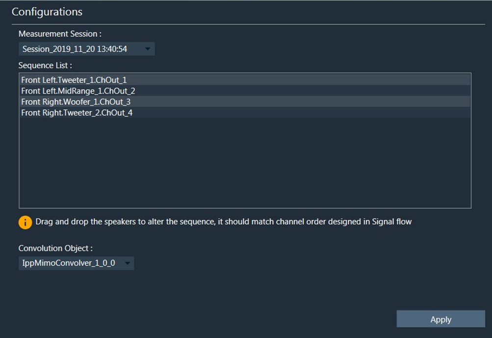
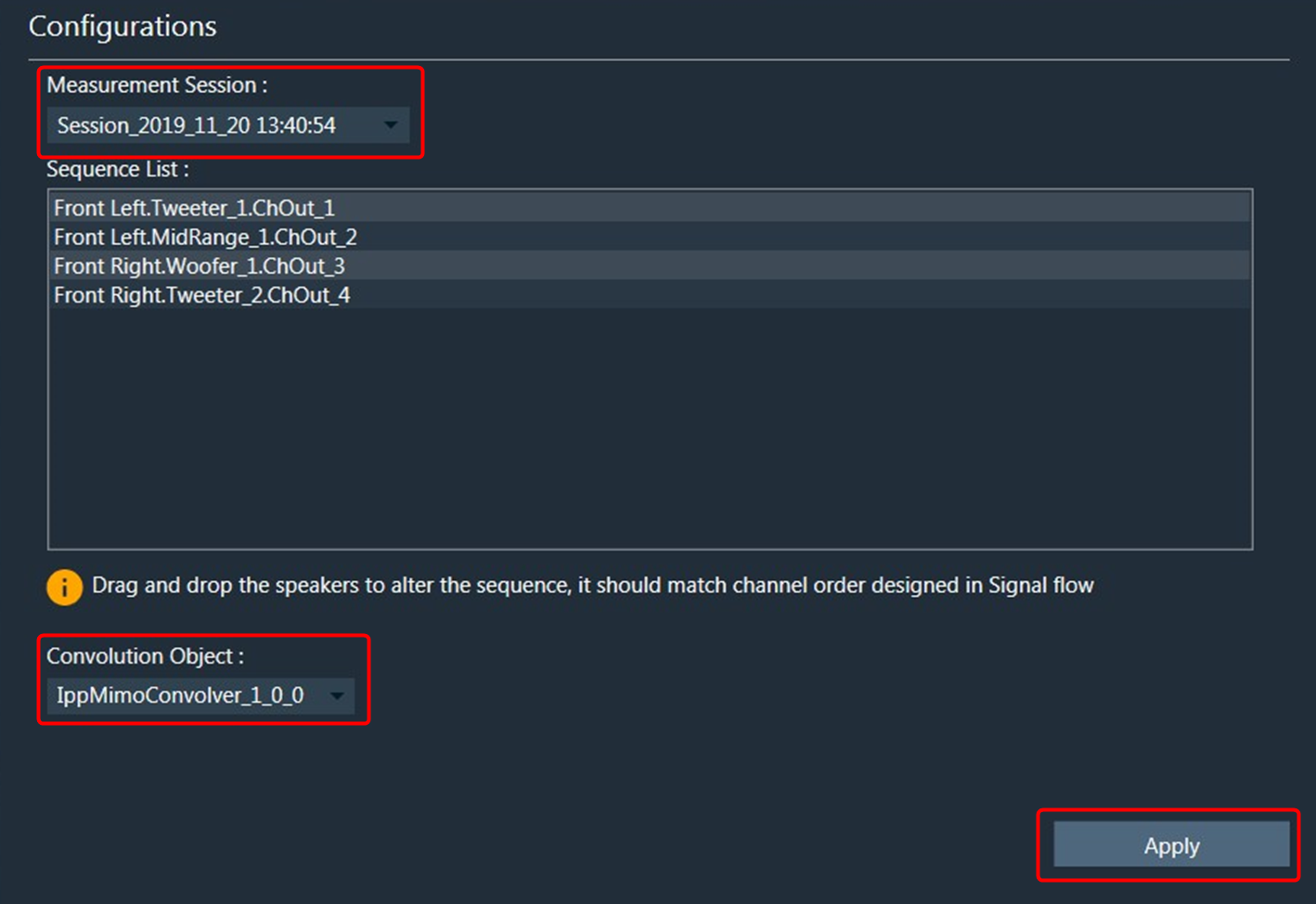
Steps to apply coefficients to Virtual Tuning:

  1. Open Virtual Tuning and select suitable Measurement Session.
  2. Select Convolution Object to which the Coefficients to be applied.
  3. Click Apply.

The selected measurement’s IRData is retrieved and applied to the convolver object. A toast message appears, stating that the coefficients were successfully applied.
Graphical user interface, text, application Description automatically generated

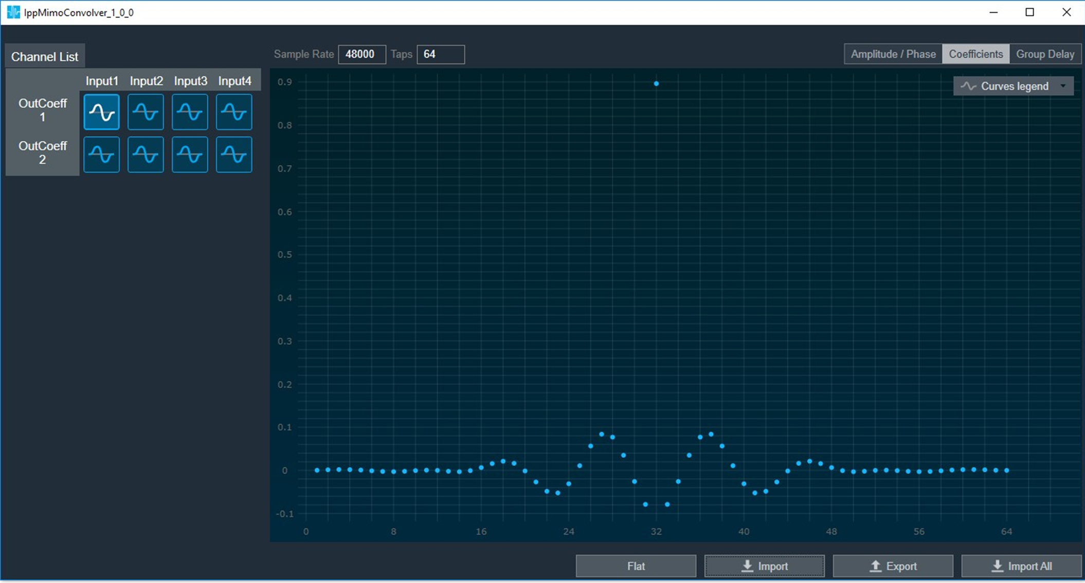
Virtual Tuning Panel: The IppMimoConvolver panel is used to view the coefficients assigned to the object. This panel provides the following functions.

  • Flat
  • Import
  • Export
  • Import All

« Import and ExportDevice Panels »
Suggest Edit
  • Careers
  • Contact
  • Sitemap
  • News

© 2025 HARMAN International. All Rights Reserved. Privacy Policy | Cookies | Terms of Use

If you are using a screen reader and are having problems using this website, please call (800) 645-7484 for assistance.