Routing in device view is supported at different levels
Device Routing
- User can connect starting from input of the Device to any virtual core inside it.
- Routing is also possible between the virtual cores. i.e., A virtual core output could be connected to the input of another virtual core.
- 1:N routing is supported at this level. i.e., A device input can connect to multiple Virtual Cores. And a virtual Core Output could be connected to multiple virtual core inputs.
- Not all the device inputs can connect to all Virtual Cores and similarly not all Virtual Cores can be connected to each other. There are few validations put in place. Please find the below list of validations for device routing.
Validations
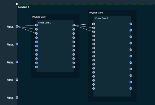
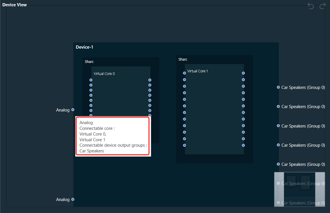
- Based on the information available on the Device, the connectable cores for a Device input is displayed whenever the user hovers on the input connection pin. Also, the connection pin name is displayed on hovering the mouse. The below image indicates the Device input pin 2 can be connected to Virtual Core 0 or Virtual Core 1.
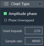
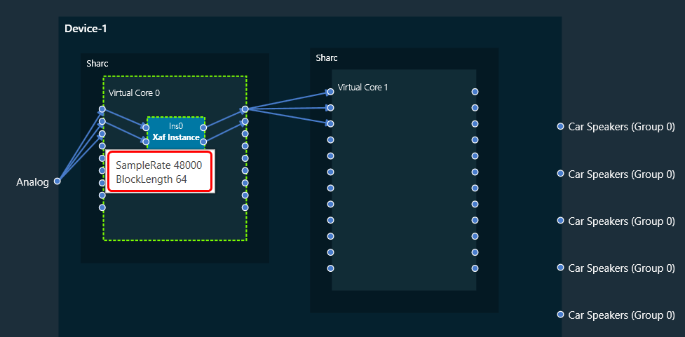
- Each Virtual Core is associated with some Sample Rate and Block Length. This information could be seen when hovered over the Virtual Core Pin.
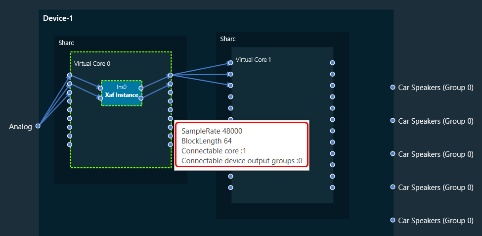
- Based on the information available on the Device, the Connectable cores and Connectable device output groups for a Virtual core output is displayed whenever the user hovers on the output connection pin. The below image indicates the Virtual core 3 output pin 3 can be connected to Virtual Core 4 or 5 or Device output group 0, 1 or 2. Virtual Core Outputs can connect to other virtual core inputs even if the sample rate and block lengths do not match.
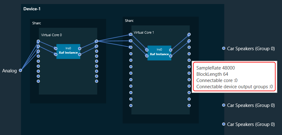
- Device output group can be known by hovering on the device output pin. In the below image the pin Speaker belongs to Group 0.
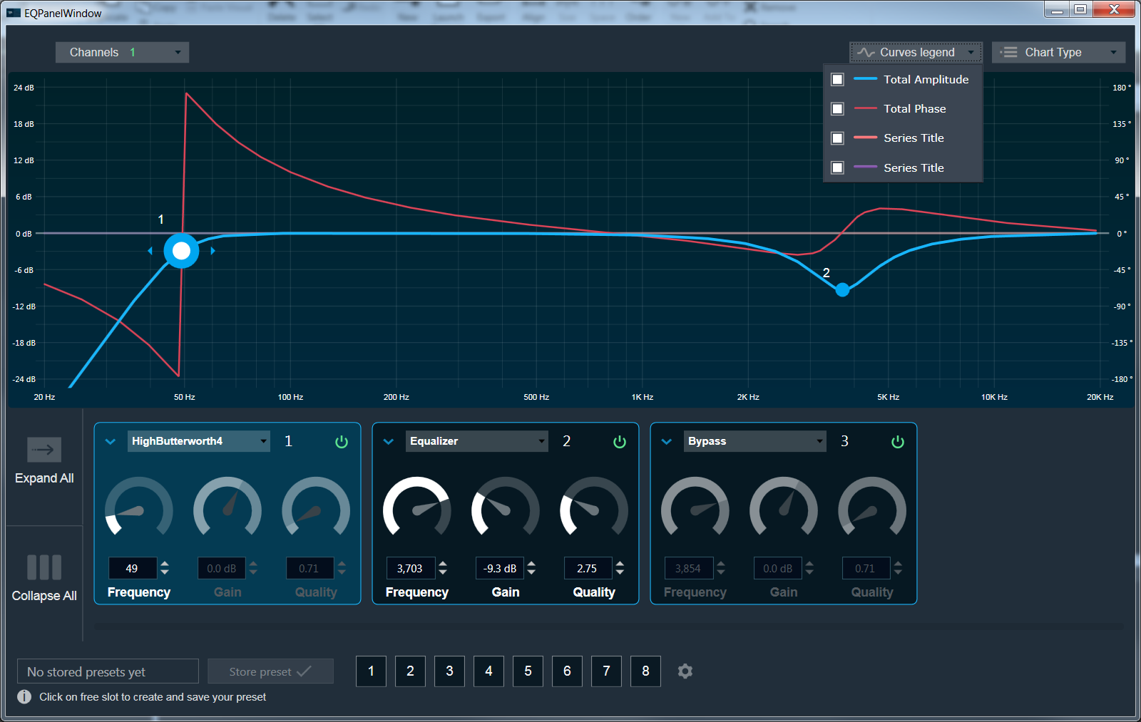
Core Routing
- User can connect starting from input of the virtual core to core objects inside it and then to the output of the virtual core.
- Connecting the virtual core input to its output is not allowed. A core object has to be put in between virtual core input and output pins.
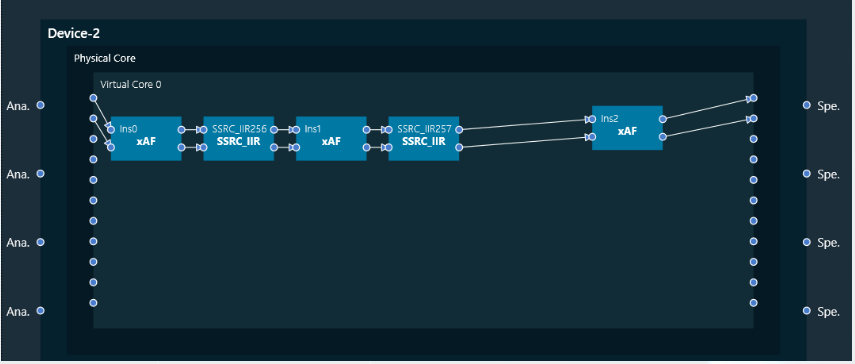
- For connecting between the instances, both the connecting core objects should have same block length and sample rate.
- If there is a need to connect two instances with different Block Length/Sample Rate, then user may use a Buffer/SSRC_IIR objects to get the desired output.
Device identification feature will only be enabled for audio libraries versions 13 and greater.