Harman Logo
AUDIOWORX
  • Home
  • Documentation
  • Videos
  • Release Notes
  • Login
Harman Logo
AUDIOWORX
  • Home
  • Documentation
  • Videos
  • Release Notes
  • Login
Harman Logo
AUDIOWORX
  • Home
  • Documentation
  • Videos
  • Release Notes
  • Login
  • Getting Started
  • User Guides
  • Developer Guides

Table of Content

Global Tuning Tool

  1. About Global Tuning Tool
    1. System Requirements
    2. Global Tuning Tool Workflow
  2. Workspace Overview
    1. Home Screen
      1. Home screen Options
      2. Application Options
    2. Device Designer Overview
      1. Tools
      2. Connection
      3. Import and Export
      4. Tuning
      5. Device Panels
    3. Devices and Template View
    4. About Core Objects Toolbox
    5. Device Operations
    6. Properties Panel
    7. Device View
    8. Help
  3. Configurations
    1. Configure State Variable
    2. Configure Default Control-Ids
    3. Configure Preset Controller
      1. Configuring Controller Slot
      2. Core Object Settings
      3. Custom Actions Settings
      4. Exporting Preset Configurations
      5. Maintain Folder Structure
      6. Loading Slots on the Device
      7. Handling Dual Responses
      8. Send Preset Data Online
    4. Link Window
    5. Configure Controller
    6. Launch MIPS Profiling
    7. Launch Memory Profiling
    8. Editing Memory Latency
    9. Configure Streaming and Polling
      1. Start Live Streaming
      2. Record Streaming Data
      3. FFT for Streaming
    10. Configure File controller
    11. Configure Control IDS
    12. Custom Device Usage
    13. Multi-xAF Library Support
    14. Configure External Endpoints
  4. Operations
    1. Create a New Project
    2. Create Signal Flow
    3. Connecting a Device
    4. Routing (Connections)
    5. Device Synchronization
    6. Launching Multiple Signal Flows
    7. Tune a Signal Flow
  5. Designing Custom Panel
    1. Panel Designer Ribbon
      1. Text Design
      2. Fader Design
      3. Rotary Design
      4. Button Design
      5. Box Design
      6. LED Design
      7. Meter Design
      8. Other Design
      9. Images
      10. Advanced
    2. Panels View
    3. Custom Panel Properties View
    4. Designer Workspace
    5. Editor Windows
      1. Parameter Address Editor
      2. Multi-Parameter Address Editor
      3. System Function Editor
      4. State Indication Setup Window
      5. Select Color Window
      6. Discrete Values Editor
      7. Indication Configuration Editor
      8. LED Values Editor
      9. Graph Parameters Window
      10. Scale Editor
    6. Create a Custom Panel in GTT
  6. Working with Parameter Set
    1. Parameter Set Overview
      1. Configuring Parameter Data
      2. Apply Delta in Parameter Sets
      3. Retrieve and Verify Parameter
      4. Import and Export Set File
      5. Preset Comparison
      6. Parameter Sets Explorer Color
      7. Switch Between Multiple Parameter
      8. Saving and Loading Set File
      9. Search in Parameter Sets
    2. Create a Parameter Set in GTT

Signal Flow Designer

  1. Overview Of Signal Flow Designer
  2. Components of Signal Flow Designer
  3. Operations in Signal Flow Designer
    1. Pin Labelling
    2. View Audio Object Metadata
    3. Column Name Configuration Panel
    4. Upgrade Audio Object
    5. Audio Object Processing State
    6. Metering the Signal Flow
    7. Copy and Paste Operation
    8. Undo and Redo Operation
    9. Block Control
    10. Signal Flow Design Validation
    11. Securing Audio Objects
  4. Create a Signal Flow
  5. Tune a Signal Flow
  6. Native Panels
    1. Launching Native Panel
    2. Common Operation in Native Panel
    3. Configuring Custom Native Panels
  7. Additional Audio Parameters
  8. Harman Audio Library Service
  9. Multiple Framework Instances Support
  10. Feedback loop in Signal Flow
  11. Compound Audio Object
    1. Create a Compound Audio Object
    2. Import and Export CAO
    3. Tuning and Editing CAO
    4. Create Preset for CAO
    5. Edit CAO Instance
    6. Set password for CAO
    7. Linking Custom Panel to CAO
    8. Multi dll support for CAO
    9. Delete a Compound Audio Object

Audio Object Description

  1. Audio Object Description Overview
  2. Interface Objects
    1. AudioIO
    2. ControlIn
    3. ControlOut
  3. Basic Objects
    1. Delay
      1. Delay Panel
    2. Gain
      1. Gain Panel
    3. Level Monitor
      1. Level Monitor Panel
    4. FaderBalance
      1. Fader Balance Panel
    5. Volume and Mute
      1. Volume and Mute Panel
    6. VolumeLite
  4. Control Objects
    1. Control Math
    2. Control Grouper
    3. Control GroupSplitter
    4. Control Multi Adder
    5. Control Mixer
      1. Control Mixer Panel
    6. Control Router
      1. Control Router Panel
    7. Control Smooth
    8. AudioToControl
    9. Lookup Table (LUT)
      1. Lookup Table (LUT) Panel
  5. Routing Objects
    1. Router
      1. Router Panel
    2. Splitter
    3. Demux
    4. Selector
  6. Source Objects
    1. Noise Generator
      1. Noise Generator Panel
    2. Wave Generator
    3. FilePlayer
  7. Mixer Objects
    1. Adder
    2. Matrix Mixer
      1. Matrix Mixer Panel
    3. Merger
    4. Fader Matrix
  8. Dynamic Object
    1. Limiter
      1. Limiter Panel
  9. Filter Objects
    1. ParameterBiquad
      1. Parameter Biquad Panel
    2. CoefficientBiquad
      1. Coefficient Biquad Native Panel
    3. Tone Control Extended
      1. Tone Control Extended Panel
    4. XoverBiquad
      1. Xover Biquad Panel
    5. FastConv
      1. Fast Conv Panel
    6. FIR Filter
      1. FIR Filter Panel

Real Time Analyzer

  1. Real Time Analyzer Overview
  2. Real Time Analyzer Components
  3. Settings
    1. Channels Settings
    2. Generator Settings
    3. Analyzer Settings
    4. Microphone Calibration
    5. RTA Advanced Settings
      1. Sound Card Settings
      2. Plugin Host Setting
      3. Advance Analyzer Settings
      4. Advance Generator Settings
      5. Graph Display Settings
      6. Mimo Convolver Settings
      7. Recorder Settings
      8. Routing Settings
    6. Saving and Loading RTA File
  4. Integrated Virtual Process Options
  5. Probe Point Configuration
  6. Real Time Data View
  7. Graph Settings and Measurement
  8. Traces
    1. Trace Toolbar
    2. Trace Configuration
    3. Trace Functionalities
    4. RTA Shortcuts
  9. Analysing Audio Signal

Measurement Module 2.0

  1. Measurement Module Overview
  2. Configurations
    1. Device Output Mapping
    2. Generator
    3. Test Sound
  3. Understand Measurement Process
    1. Scene Setup
    2. Speaker Configuration
    3. Microphone Configuration
    4. Define Measurement
    5. Measurement Session

Central Viewer

  1. Central Viewer Overview
  2. Central Viewer Window
    1. Configurations
    2. Scene Mode
    3. Chart Selector
    4. Waterfall Chart
    5. Graph Area
    6. Curve Lists
    7. Domain Selector
  3. Import Export Central viewer settings

Starter Kit Utility Tool

  1. Starter Kit Utility Tool
  2. Useful Commands for Starter Kit
  3. Starter Kit Troubleshooting
  • Global Tuning Tool
  • Configuring Controller Slot

3.3.1.Configuring Controller Slot

Steps to configure preset controller slot:

  1. Go to the Standard toolbar and open Preset Controller.

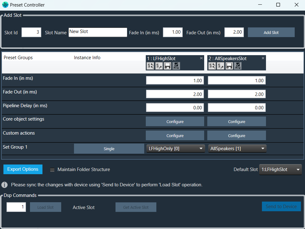
    On the Preset Controller window you can see the following details:

    • In the Slot Id, the serial number starting from 1 (or the next available slot) will be displayed.
    • The Slot Name, Fade In, and Fade Out will be filled in with default values.
    • All the Set groups created in parameter sets screen containing the parameters of the device are displayed as rows in set map table.
  2. Enter the values in Slot Id, Slot Name, Fade In, and Fade Out, and click Add Slot.

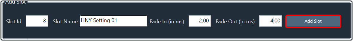
    A new slot column added with entered details and default value (None) for set groups available in the table.
  3. Enter the Pipeline Delay in the text box. The pipeline delay is used as a delay after applying the preset to the Load Slot operation and before starting to ramp up. The pipeline delay is the time required for the history buffers (which have already been cleared) to be filled with valid data before the start of the ramp-up. The value can be set from 0 to 65535 ms.
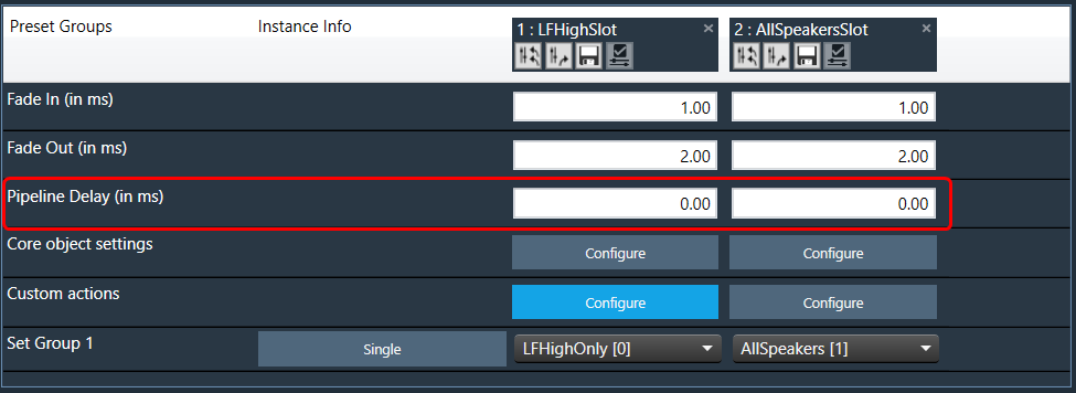
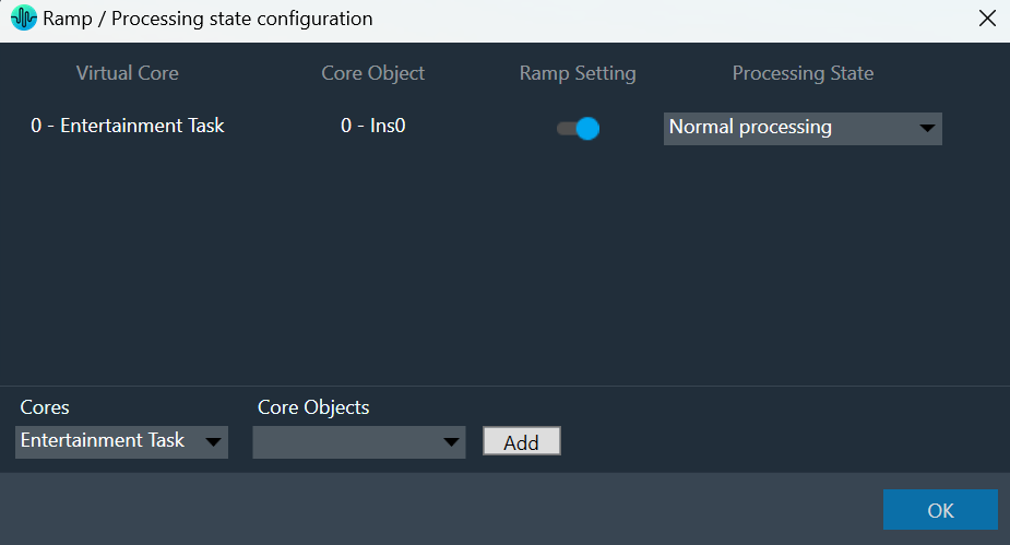
  4. In the Core object Setting row, click Configure. This opens the Core state configuration window.
  5. On the Core object configuration window, Enable or Disable ramping for individual core objects using the toggle button.
    Instances which have active set groups in this slot will automatically be added to this window and cannot be removed.
    For more details about Core object configuration, refer to Core Object Settings
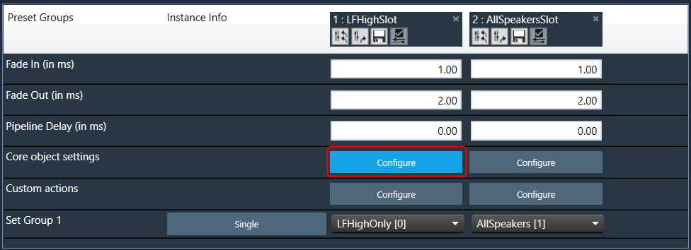
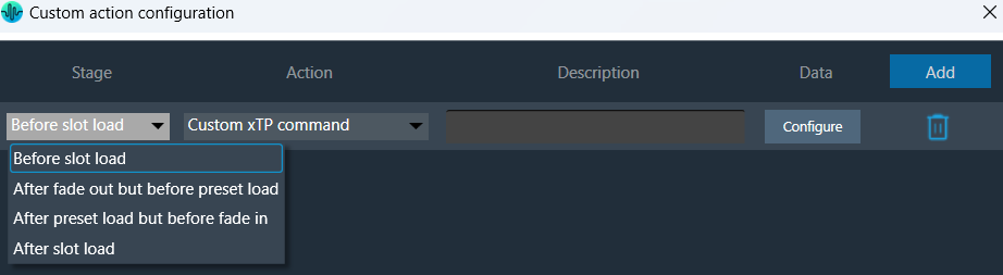
  6. (Optional) If you want to add custom actions, in the Custom actions row, click Configure. This opens the Custom action configuration window.
    On this window you define custom actions.  For more details about Core object configuration, refer to Custom Actions Settings
  7. In the Set Group row, click on the drop-down to set a group created in the parameter sets screen.

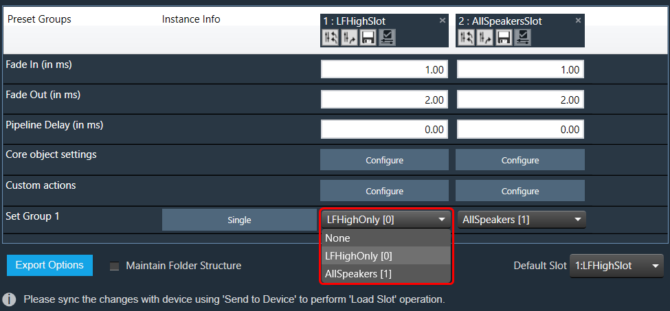
    If the “None” value is selected for any set group no parameter set from that group is loaded for this slot.
  8. Click on the Single to see the core and instance.
    The instances associated with the set group are shown next to the set group. If the group contains parameters of only one instance, the instance info is “Single”, otherwise it will display “Multiple”.
  9. Double-click on the table column header to edit the slot name.

    Ramp Settings configuration is supported from S+2 device library version.

  10. Click on the “X” icon available on any column to delete the slot.

Slot Options

Retrieve Slot: The Retrieve Slot option in the generic sets window reads the state variable values of all the sets in a slot and updates them in the in the corresponding sets of Parameter Sets. Retrieve Slot button is available in the header of each slot.

Apply Delta Slot: The Apply Delta Slot feature only sends tuning values of the parameter which is updated in the slot. The tuning values of the presets are send to the device via XTP Tuning write messages. Apply Delta Slot option is available in the header of each slot.

Export Slot: Once you have created a Set Map, click on the “Export Slot” option, and browse the desired path.

Flash file created in binary format. For virtual devices, use the file name as “sect262144.flash”.

Generic sets are persisted in the database, just like any other data in GTT.

Generic sets are also persisted in the .gttd file when the project is exported, and the same is available after importing. The selection of the default slots is dynamic and will not be persisted.

Verify Slot: This functionality is designed to compare the presets loaded on a device with those available in the GTT  in order to ensure their accuracy.

This feature is available only in online mode. i.e. only when the device is connected.

To verify preset values, select a slot and then click the ‘Verify slot’ option. A read command is sent to the device for each state variable within of all presets under a slot. Once the value has been read, it will be compared with the corresponding value in the preset. If all values match, the verification process is considered successful. However, if any values do not match, an error message will be displayed, and an error report will be generated.

Sample error report is as attached here Set 1[2].

« Configure Preset ControllerCore Object Settings »
Suggest Edit
  • Careers
  • Contact
  • Sitemap
  • News

© 2025 HARMAN International. All Rights Reserved. Privacy Policy | Cookies | Terms of Use

If you are using a screen reader and are having problems using this website, please call (800) 645-7484 for assistance.