//============================================================
// (C) 2017 Harman International Industries, Incorporated.
// Confidential & Proprietary. All Rights Reserved.
// ============================================================

/*!
*   file      AwxiAudioObjExtMemRecs.cpp
*   brief     Memory related description Source file
*   details   Implements the audio object memory related API
*   details   Project    Extendable Audio Framework
*   copyright Harman/Becker Automotive Systems GmbH
*
       2020
*
       All rights reserved
*   author    xAF Team
*/

/*!
*   include files required to request the dynamic memory
*/
#include "AwxAudioObjExtMemRecs.h"

xUInt8 CAwxAudioObjExtMemRecs::getMemRecords(xAF_memRec* memTable, xAF_memRec& scratchRecord, xInt8 target, xInt8 format)
{
	xUInt8 numMemRecords = (static_cast(ENABLE_BLOCK) == m_EnMemory) ? static_cast(NUM_MEM_RECORDS) : static_cast(FLOATARRAY);
	//m_Param memory
    memTable[PARAM].alignment = 4;
    memTable[PARAM].size = static_cast(static_cast(m_NumAudioIn) * NUM_PARAMS_PER_CHANNEL * sizeof(xFloat32));
	memTable[PARAM].label = "Tuning Parameters";

	//m_Coeff memory
    memTable[COEFF].size = static_cast(static_cast(m_NumAudioIn) * sizeof(xFloat32));
	memTable[COEFF].alignment = 4;
	memTable[COEFF].label = "Gain Values";

	//m_MemBlck memory(Abstracted Tuning Memory)
	if (static_cast(ENABLE_BLOCK) == m_EnMemory)
	{
		memTable[FLOATARRAY].size = FLOAT_ARRAY_SIZE * sizeof(xFloat32);
		memTable[FLOATARRAY].alignment = 4;
		memTable[FLOATARRAY].label = "Abstracted Tuning Memory values";
	}
    return numMemRecords;
}
Audio Object Example – AwxAudioObjExtToolbox.h
// ============================================================
// (C) 2017 Harman International Industries, Incorporated.
// Confidential & Proprietary. All Rights Reserved.
// ============================================================

/**
*   file      AwxAudioObjExtToolbox.h
*   brief     AwxAudioObj Audio Object Toolbox - Header file
*   details   Project    Extendable Audio Framework
*   copyright Harman/Becker Automotive Systems GmbH
*
       2017
*
       All rights reserved
*   author    xAF Team
*   date      March 28, 2023
*/

#ifndef AWXAUDIOOBJEXT_TOOLBOX_H
#define AWXAUDIOOBJEXT_TOOLBOX_H

/*!
*   xaf mandataory includes
*/
#include "AwxAudioObjExtMemRecs.h"
#include "AudioObjectToolbox.h"
#include "XafDefs.h"

/** here you can add all required include files required for
    the core functionality of your objects
**/

class CAwxAudioObjExtToolbox : public CAudioObjectToolbox, public CAwxAudioObjExtMemRecs
{
public:
    /**
    *    Default ctor / dtor to initialite member variables of the audio object
    */
    CAwxAudioObjExtToolbox();
    virtual ~CAwxAudioObjExtToolbox();

	/**
    *    Returns the object description
    *    return pointer to structure describing object configuration.
    */
    const tObjectDescription*   getObjectDescription() OVERRIDE;

	/**
     *    Writes object template information to the buffer returns number of bytes written
     *    param  info   audio object tuning info.
     *    param  buffer buffer for XML output.
     *    param  maxLen maximal length of the buffer.
     *    return size of generated xml file.
     */
	xUInt32 getXmlObjectTemplate(tTuningInfo* info, xInt8* buffer, xUInt32 maxLen) OVERRIDE;

	/**
     *    brief  Returns the overall object description used in the object
     *            within the device description file
     *    param  info pointer to TuningInfo structure
     *    param  buffer pointer to buffer used for file creation.
     *    param  maxlen max allowed size of generated file.
     *    return size of generated device.ddf file.
     */
	xUInt32 getXmlFileInfo (tTuningInfo* info, xInt8* buffer, xUInt32 maxLen) OVERRIDE;

	/**
    *    Returns the mode description of object
    *    param  mode    index of the selected mode
    *    return pointer to the object mode description
    */
	const tModeDescription* getModeDescription  (xUInt32 mode) OVERRIDE;

	/**
    *    This function sets the object configuration based on user settings indicated in GTT
    *    param  configOut   the configuration of the object sent back to the tool
    *    return error code
    */
	xAF_Error getObjectIo(ioObjectConfigOutput* configOut) OVERRIDE;

	/**
     *    Returns the additional variable description
     *    param  index   index of the additional parameter
     *    return instance of additional variable description
     */
	const additionalSfdVarDescription* getAdditionalSfdVarsDescription(xUInt32  index) OVERRIDE;

	/**
      *    brief  Creates metadata entries for the specific audio object
      *            this function must be overridden by each object supporting
      *            the metadata feature. Otherwise default data will be created.
      */
	void createStaticMetadata () OVERRIDE;

	/**
     *    brief  Creates mode and configuration dependent metadata entries for the specific audio object
     *            this function must be overridden by each object supporting
     *            the metadata feature.
     *    param  configIn  the configuration of audio in, out and num elements passed in by the design tool
     *    param  configOut the configuration of the object sent back to the tool
     */
    void createDynamicMetadata(ioObjectConfigInput& configIn, ioObjectConfigOutput& configOut) OVERRIDE;
protected:
};
#endif //AWXAUDIOOBJEXT_TOOLBOX_H
Audio Object Example – AwxAudioObjExtMemRecs.h
// ============================================================
// (C) 2017 Harman International Industries, Incorporated.
// Confidential & Proprietary. All Rights Reserved.
// ============================================================

/**
*   file      AwxAudioObjExtMemRecs.h
*   brief     Simple demo Audio Object MemRecs - Header file
*   details   Project    Extendable Audio Framework
*   copyright Harman/Becker Automotive Systems GmbH
*
       2017
*
       All rights reserved
*   author    xAF Team
*   date      July 7, 2021
*/

#ifndef AWXAUDIOOBJEXT_MEM_RECS_H
#define AWXAUDIOOBJEXT_MEM_RECS_H

/*!
*   xaf mandataory includes
*/
#include "AwxAudioObjExt.h"
#include "MemRecordProperties.h"

/** here you can add all required include files required for
    the core functionality of your objects
**/


class CAwxAudioObjExtMemRecs : public CAwxAudioObjExt, public CMemoryRecordProperties
{
public:

    xUInt8 getMemRecords(xAF_memRec* memTable, xAF_memRec& scratchRecord, xInt8 target, xInt8 format) OVERRIDE;
};
#endif //AWXAUDIOOBJEXT_MEM_RECS_H
Adding external audio object into AudioworX package
External audio objects can be added to the framework without re-compiling the libraries provided by AudioworX. There are following use cases to be supported:
- Third party audio object code to be compiled and linked (Source and headers placed in specific folder)
- Third party audio object is already pre-compiled and libraries needs to be linked (header + library)
General assumption is that each use case can be satisfied for multiple 3rd party objects which are added to the extAudioObject.lib which itself needs to be linked to the application code on the target or to the xAFVirtualamp.dll based on one of the 3 mentioned use cases. It must be ensured all use cases can be used in parallel for different objects which means, every 3rd party object can be integrated individually by following one of the 3 proposed solutions or a combination of them. After a successful compilation and linking process a post-build step shall be applied to validate that all mandatory APIs for all added objects have been implemented correctly.
Common pre-requisites for all use cases
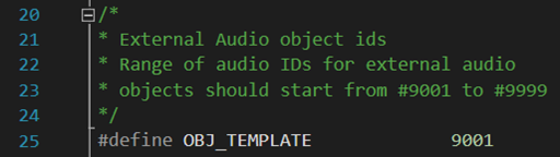
- Define unique audio object id
- #define OBJ_TEMPLATE 9001
- extendable-audio-frameworkexternalincExternalObjAudioIds.h or project specific path and name
- make sure the defined id is in the range of 9002 and 9999 and not used by any other object ID
- object name, c++ class name and header file names are matching the name used in the #define. E.g. user is creating MyObject ->
- #define OBJ_MYOBJECT 9002;
- C++ class name CMyObject (C is mandatory, camel case is optional)
- MyObject.h
- MyObjectMemRecs.h
- MyObjectToolbox.h
- Tell the build script which files to be picked up
- Directly in cmake by adding cpp files and libraries to be compiled and linked
- Path to a CmakeLists.txt file containing all required information
Third party code to be compiled and linked (Source and headers placed in specific folder)
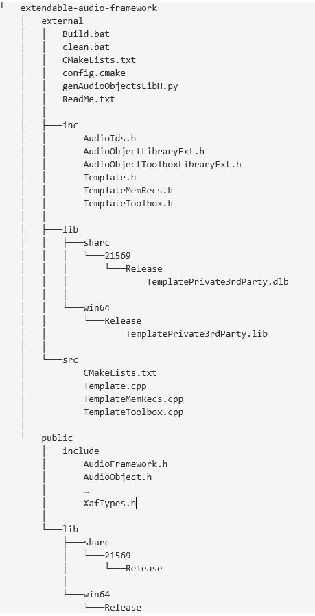
The external 3rd party build solution allows the developer to add source files, header files and libraries into a predefined folder structure. The Template audio object shall be used as a reference example on how to implement the third party code the for the external object. The CMakeLists.txt in the external folder must be modified accordingly to include the newly added cpp file(s) and library(s).
Folder structure for external audio object.
Third party object is pre-compiled and needs to be linked only (header + library)
This use case assumes that external object(s) has been build according to AWX specifications and the result of this build is supposed to be linked to other audio objects in the xAFVirtualAmp.dll. To achieve this, the developer must add the following files into the external sub folders:
- Inc
- Myobject.h
- MyobjectMemRecs.h
- MyobjectToolbox.h
- Lib
- xafMyObject-lib_release.ext (.ext ==.lib, .dlb, etc. based on the target)
- MyObjectPrivate.ext
The folder structure and naming inside the lib folder must match the ones which are released within the xafpubliclib. The developer must ensure, that libraries are available for all supported targets (WIN64, Sharc, etc.) and placed properly in the correct sub-folders. In addition to that, the CMakeLists.txt must be changed to link the additionally added libraries. The Release cmake file will have a section with proper comments on how to do so. There will be additional .bat file will be provided to make it convenient for the end user for linking and creating .dll
Building External AO
Prerequisites
1. Developer should generate the corresponding libraries before starting the build process execution. Otherwise, there will be errors when executing the batch file Build.bat.
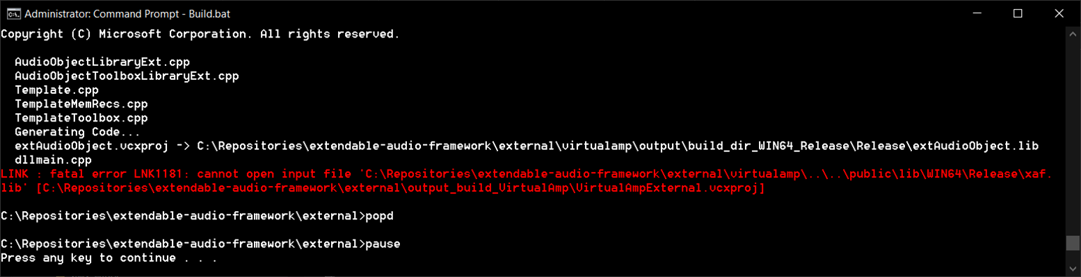

For generating xAF libraries:
python build.py --platform=WinPc --target=Win64 --program=allExtObjects --profile=Release
For generating AWX VirtualAmp:
python build.py --target=Win64 --program=virtualAmp --profile=Release --group=all
2. Place the the external audio object’s source code under externalsrc.
3. Place the external audio object header file under externalinc . The header file name should be equal to the external audio object class name. For example, if the audio object name is CTemplate, the header file name should be Template.h.
4. Make sure the external audio object’s pre-processor macro is defined in file externalincExternalObjAudioIds.h. The name should be OBJ_”header file name” and the value should be in the range between 9002 and 9999.
E.g. Audio Object Template ID:
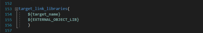
5. If additional libraries need to be linked, add them in the file CmakeLists.txt located in:
extendable-audio-frameworkexternalsrc
Steps for building Audio Object Template
1. Open a command prompt window in Admin mode.
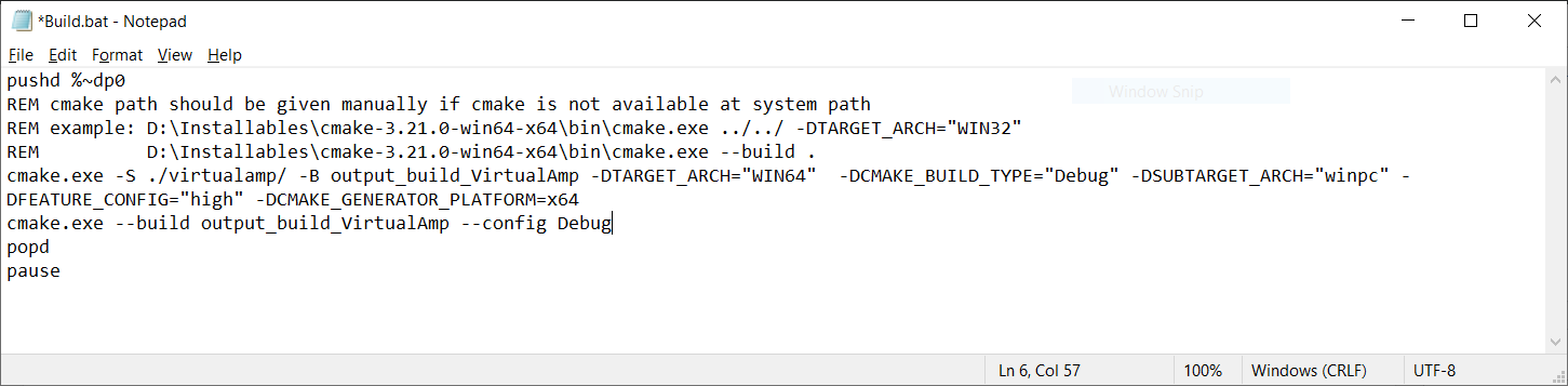
2. Execute the batch file Build.bat
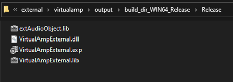
3. After the build process is complete, the corresponding VirtualAmpExternal.dll file will be available at the path externalvirtualampoutputbuild_dir_WIN64_ReleaseRelease.
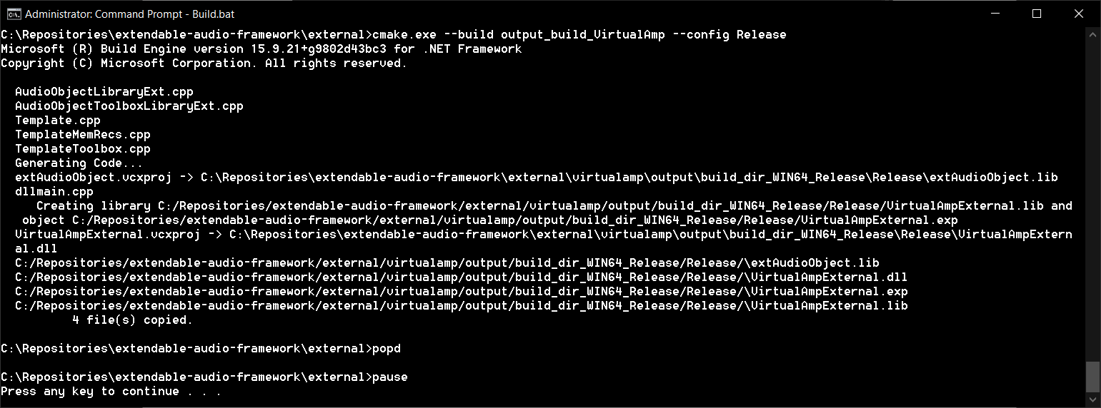
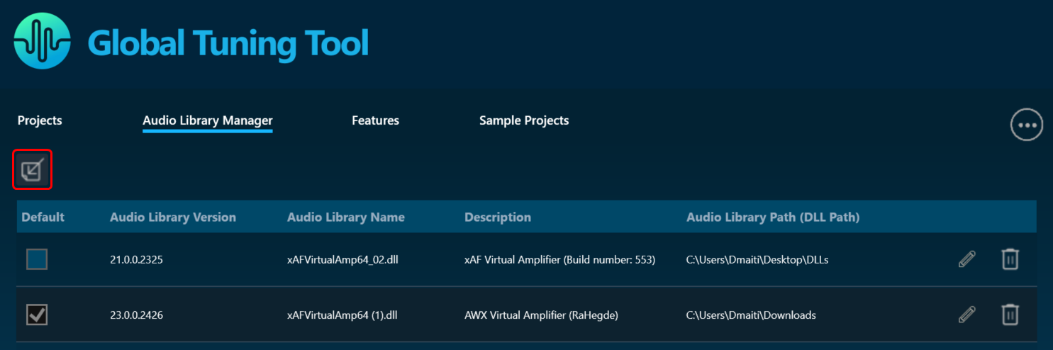
4. The generated .dll file can be imported as an audio library into GTT to update the toolbox with the newly added audio object(s).
If the developer needs to use debug build mode to make sure everything is working as expected, the file Build.bat can be modified accordingly by changing -DCMAKE_BUILD_TYPE=”Release” to -DCMAKE_BUILD_TYPE=”Debug” and –config Release to –config Debug.
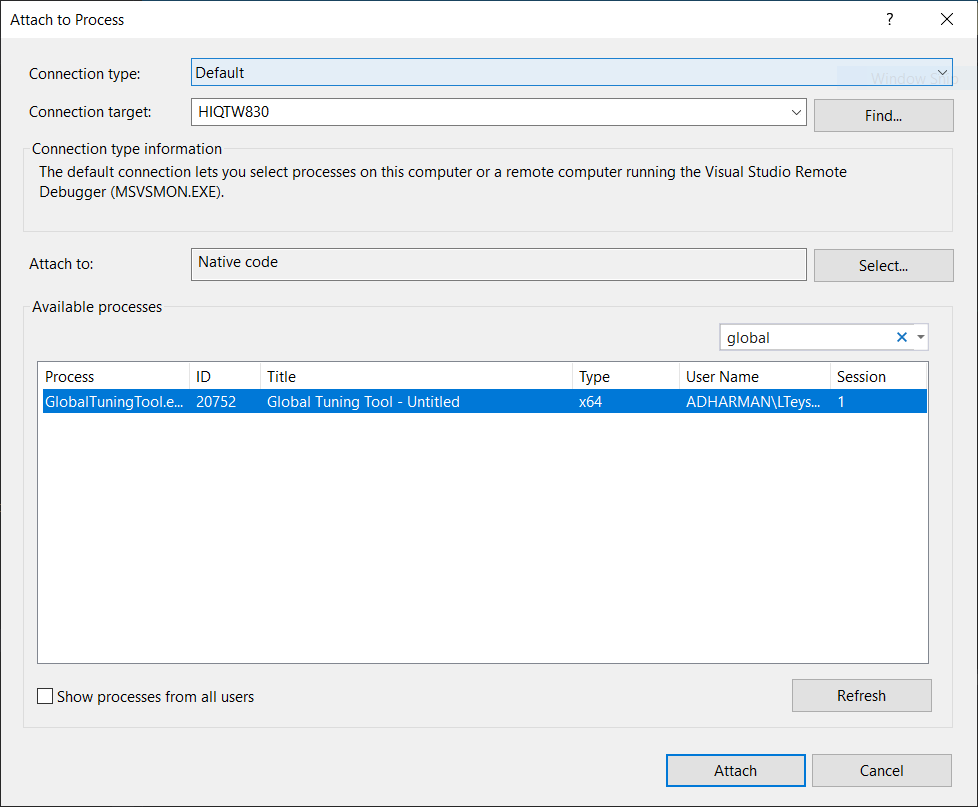
To debug the audio object in Visual Studio, the developer has to select the option Debug->Attach to Process… Then, select Attach to: Native code. Finally, filter out the desired process:
– Toolbox:

– Calc function and tuning:
Overview
The audio object developer must create the three classes listed below in order to create any new algorithms or audio objects.
- Audio object class that inherits CAudioObject base class.
- Audio object memory record class that inherits Audio object class and CMemoryRecordProperties base class.
- Audio object tool box class that inherits CAudioObjectToolbox base class and Audio object memory records class.
Audio object Class
- CAudioObject: The CAudioObject base class has all the hooks to interact with the framework that in turn provides the hooks to the outside world. By inheriting CAudioObject, the audio object developer needs to simply implement the features they require for their new audio object and all the hooks would automatically be provided.
Additionally, the CAudioObject provides default implementations, such as bypass, that the object developer would get without having to write any additional code. - CAudioObjectToolbox: By inheriting CAudioObjectToolbox all the hooks would automatically be provided to the tuning tool.
- CMemoryRecordProperties:The CMemoryRecordProperties provides hooks to add memory records for generic and processor specific records.
These classes should be declared in the separate header files.
In this guide all examples and explanations are given for creating AudioworX objects based on source code. However, the audio object developer can still inherit the CAudioObject base class and implement its methods by calling methods of their own non-AudioworX ported libraries. As long as a public header file is provided and a library is linked, this approach is valid.
Source Code Type
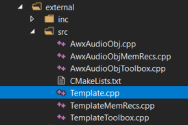
The audio object developer must split the implementation of these classes into at least three source code (cpp) files:
- generic: This file implements generic source code (not processor specific) for the embedded functionalities, i.e. init, calc, tuneXTP etc.
- toolbox: This source code file implements code that will only be used and compiled for use with GTT. This code will not be part of any embedded library. The contents of this file describe the interaction of the object in GTT during design time and provides metadata that will assist the user in configuring the object during signal flow design
- memrecs: This source file implements the code to add memory records required for audio objects
- processor: Processor specific optimizations are usually implemented in their own separate source code files that are only compiled for the given processor. These processor specific files will work in conjunction with the generic file and they do not have to re-write it.
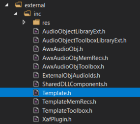
For example below is snapshot of files used in template audio object for Generic, Memory record, and Toolbox implementation.

Once the audio object development is complete, two libraries must be compiled:
- A toolbox one that will be loaded into GTT.
- A processor/target specific one.
Basic Features and APIs
Below are the features that most developers will need during their audio object development. The order the methods get called during initialization may be helpful to audio object developers.
The Audio object constructor is called by the framework. Audio Object developers should use the constructors to initialize their classes to a suitable state. No member variables and pointers should be un-initialized.
CAudioObject::CAudioObject()
The constructor initializes various member variables.
This method is an abstract method in the base class so it MUST be implemented by every audio object. This simply returns the class size of the given audio object.
/**
*    Returns the size of an audio object
*/
virtual unsigned int getSize() const = 0;This function initializes all internal variables and parameters. It is called by the framework (CAudioProcessing class). In this method, the object should initialize all its memory to appropriate values that match the device description specified in the toolbox methods (getXmlFileInfo, etc)
void CAudioObject::init()
{
}
If the audio object requires additional configuration variables, then the user must also implement the method to initialize that data via assignAdditionaConfig(). For more details, refer Audio Object Additional Configuration.
If this method is not overwritten, it is an empty method that will not do anything.
The calc() function executes the audio object’s audio algorithm every time an audio interrupt is received. This function is called when the audio object is in “NORMAL” processing state only. This function takes pointers to input and output audio streams and is called by the CAudioProcessing class when an audio interrupt is received.
The audio inputs and outputs are currently placed in two different buffers for out of place computation. xAF expects audio samples stored in input buffers to be processed and stored in output buffers.
void CAudioObject::calc(xAFAudio** inputs, xAFAudio** outputs)
{
}
If the object/algorithm does not have any logic to execute during an audio interrupt, this method does not need to be overridden. By default, it is empty. For example, some control objects do not need to execute any logic during an interrupt and, accordingly, they do not override this method.
This functionality alerts an object when its parameter memory is updated or modified. It provides information on the exact variables that were modified and allows the object to update internal variables accordingly. An example is in a filter block, where a parameter update (for example a gain/frequency/q change) triggers the recalculation of the filter coefficients in the tuning code. The API triggered is CAudioObject::tuneXTP().
void CAudioObject::tuneXTP(int subblock, int startMemBytes, int sizeBytes, xBool shouldAttemptRamp)
{
}
An ID-based memory addressing scheme is used instead of pure memory offsets. The CAudioObject→tuneXTP() method is called by the framework in CAudioProcessing→setAudioObjectTuning().
CAudioObject::tuneXTP() take in four integers representing the:
- sub-block: index of the sub-block in the audio object.
- startMemBytes: memory offset (in bytes) from the beginning of the sub-block memory.
- sizeBytes: number of the parameters tuned (size in bytes).
- shouldAttemptRamp: flag to indicate audio object should attempt to ramp the tuning parameters or not.
The subblock, startAdr and size are passed into the audio object to enable the calculation of the elements it needs to tune.
Implementation
Once triggered, the function’s implementation is heavily dependent on the audio object itself and on the corresponding tuning panel (or Device Description/ memory layout) that the tuning tool will use to tune the audio object.
Inside this method tuneXTP(), the received tuning data is NOT checked for valid range limits.
– If the Audio Object (AO) is tuned from GTT, the GTT ensures that the tuning parameters remain within the range prescribed by the toolbox methods.
– If the Audio Object (AO) is tuned using methods other than GTT, like SVE or xTP tuning, it is the responsibility of those entities to ensure that the tuning parameter values remain within the valid range as mentioned in the Audio Object Description User Guide.
The developer needs to take into consideration the following while designing an object:
- The set file header size. If an object uses a large number of sub-blocks, each sub-block will require additional header data to store its values in the initial tuning file.
- The number of sub-blocks. If there are a lot of sub-blocks, and developers are tuning a big chunk of data, there will be many more xTP messages sent compared to an audio block with fewer sub-blocks.
- The calculations required. Having more sub-blocks can reduce the calculations required in the AudioObject::tuneXTP() functions. The audio object can focus on calculations for a narrower section of audio object memory, which is the sub-block.
For example, if a parameter biquad block is being tuned, the index or sub-block ID passed in by the CAudioProcessing class could determine:
- If a specific channel is being tuned. Once triggered, the function should:
- Recalculate the filter coefficients characterizing all filters of that specific Biquad channel.
- Use the memory offset and size variables to recalculate only the filter coefficients whose corresponding parameters were modified.
- A specific filter within a specific channel. Once triggered, this will only compute the coefficients of a single filter.
The xAF team has implemented the Parameter biquad block with the sub-block definition referring to a channel in the biquad block rather than one specific filter. The xAF also uses memory offset and sub-block to recalculate as few filter coefficients as possible.
Examples of what the tuning methods of each individual Audio Object trigger are listed below:
| Audio Object | Description |
| Delay | Sets the delay time in milliseconds. Each channel may have different delay and update buffers. |
| Gain | Sets the gain of each channel. |
| Parameter Biquad | Sets the type, frequency, gain, quality of a filter and recalculate filter coefficients for all filters in a channel. |
| Limiter | Sets the limit gain, threshold, attach time, release time, hold time and hold threshold. |
| LevelMonitor | Sets the frequency and time weighting of level meter. |
Audio object control is carried out through CAudioObject→controlSet(). When a control message is received, it triggers the CAudioProcessing→setControlParameter(..) function, which in turn triggers the Control Input object control function, ControlIn→controlSet(..).
This then routes the control from the control input object to each object intended to receive the message through the audio object controlSet() method.
virtual int controlSet(int pin, float val);where pin: is the input control pin index being updatedval: the new value the control pin is being updated with
Objects that can be modified by control variables like volume, need to configure their object class control input and output values. These control I/Os are determined during the design of the audio object and can depend on the user configuration of the object during the signal design stage.
For example, a volume audio object will have multiple audio input and output channels. It will also have an input control that receives volume changes from the HU and an output control that relays those changes to other objects that depend on volume control.
These pins are a one to one connection between objects. If, at the output of the volume object, the volume control needs to be forwarded to multiple audio objects, the signal designer must add a control relay (ControlMath->splitter) object that can route those signals to multiple objects.
The implementation of this function is specific to the audio object. For example, a volume audio object control command will fade the volume value in the audio object starting from the old gain value and ending with the new gain value sent through the control command.
An object can also pass control to another object connected to its control output via the following CAudioObject→setControlOut(..) method. This method identifies which object should receive the output and passes the value to it.
/*!
*   Helper method for writing control to mapped outputs
*   param index - which of the object's control outputs we are writing to
*   param value - value we are writing out to the control output
*/
void setControlOut(int index, float value);
To be able to externally read the value of a control variable from an audio object, that data must be placed in the state memory of the object and described in the description file used by the GTT tool. This is done through the Device Description section.
Finally, objects that do not interact with any controls do not need to override this method.
controlSet MUST NOT write to another objects memory, if that memory is part of a larger block of memory that must be changes altogether. For example, controlSet must not write into memory containing filter coefficients because changing one coefficient alone is bound to break the filter behavior
Advanced Features and APIs
These methods are optional and are usually used for more advanced algorithms that have a large memory footprint or require advanced features like live streaking.
This code will be compiled for embedded libraries and used at runtime.
Audio Object Additional Configuration
This is the first method called by the framework to the object after its properties are setup according to the signal flow configuration. This method allows the object the opportunity to setup its configuration. The framework retrieves the additional configuration data the object is expecting from the signal flow file and sets these two audio object variables:
- m_AdditionalSFDConfig – this is a void pointer that holds the additional configuration data
- m_SizeofAdditionalVars – this variable will contain the size (in bytes) of the additional data
The object is then responsible for configuring its internal states based on this data provided. The API to implement is:
void assignAdditionalConfig()
{
}
An example is provided below for the delay audio object.
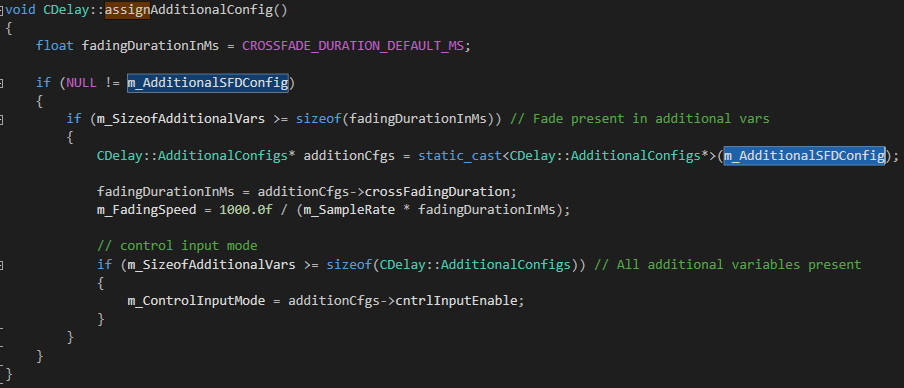
In the toolbox configuration, the delay object specifies it has the following 2 additional configuration variables:
typedef struct AdditionalConfigs
{
xFloat32 crossFadingDuration;   ///< first additional config param == Crossfading duration
xUInt8 cntrlInputEnable;        ///< second additional config param == Control input mode (disabled, oneSet, multiset)
}
So, accordingly, this is the data it expects as the output from the tool once the signal flow is designed.
The endianness of this additional configuration data is passed to the object in little endian format.
The Sub-blocks represents logical divisions of a block’s (or audio object’s) memory. They are partitions of the audio object’s memory.
There are many reasons to use sub-blocks in an object.
- Tuning data preservation is facilitated by the use of sub-blocks.
- The data can be organized into more logical chunks.
- The data will also be easier to debug.
- In some cases, tuning preset files can store much less data. This is due to the fact that sub-blocks of the memory can be individually stored in the preset files as opposed to the entire object’s memory.
Sub-blocks belonging to the same object do not necessarily need to have the same sub-block size.
The two API calls associated with setting up sub-blocks in an object are:
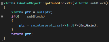
xInt8* getSubBlockPtr(xUInt16 subBlock)
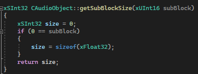
xSInt32 getSubBlockSize(xUInt16 subBlock)
- getSubBlockPtr() is called by the framework to retrieve pointer to start of the subblock.
- getSubBlockSize() is called by framework to get size of the subblock in bytes
Here we will create an example of a simple object. This object has one parameter (m_Gain). It’s a float so its size is four bytes. Since it is our only parameter we will only have one subblock it’s subblock will be zero (we start at zero).
In this code we only return a valid pointer if our subblock is as expected. If subblock is zero then we return a pointer to our parameter memory – which in this case is the address of our member float. Memory referenced doesn’t have to be a member variable of course, often it is a reference directly to a requested memory record. Sometimes objects will allocate one record but map several subblocks to the memory, spacing them out appropriately. You are free to do what you want as long as you don’t reference global memory as your object has to support multiple instances.
Likewise for this method the return for an error case is the default (0). If the framework sees a 0 size record or nullptr returned from the subblock method it will return an error over xTP and not attempt to write out of bounds. It will also return an error if address + size in the tuneXTP method exceeds the bounds dictated here. (Eg: subblock size is 16, but I want to write 8 bytes starting at address 12, this would be denied).
Whether your data is defined in DDF as ‘Tuning’ or ‘State’ it still will have a subblock. The following fields in GTT’s SV Viewer.
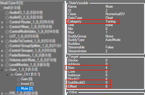
In the above picture we can see how this information translates to the DDF side.
SubBlockID is the same subblock as above. Offset is your address within the subblock, size is the size of the variable. You can also see above the category here is ‘Tuning’. A subblock is either ‘Tuning’ or ‘State’ and it cannot be split between them.
If an audio object not require any sub-blocks (no tuning or state parameters), these methods don’t need to be overridden.
Design Time Configuration
The steps below are the minimum required to setup the configuration of an audio object that can be designed from SFD. The base class (CAudioObject) methods must be overridden and the framework will use these overridden methods to provide structures to inform SFD of your object’s settings. These methods are provided to GTT/SFD via a DLL interface.
The designing of the audio object, start with configuring object descriptions.
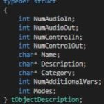
The object description describes the default configuration of the object, when the object is dragged into signal flow designer view in GTT. Default configuration of the object will be Name, Description and Category of the object. Additionally, supported operating Modes and the objects required Additional configuration variables.
The table provide details of description of variables :
|
Member
|
Description
|
|
NumAudioIn
|
This is the default number of audio inputs. It can be overridden as the object is configured.
|
|
NumAudioOut
|
This is the default number of audio outputs. It can be overridden as the object is configured.
|
|
NumControlIn
|
This is the default value, which can be overridden during the design of the audio object and refers to the number of input control signals an object receives.
|
|
NumControlOut
|
Same as NumControlIn but for output.
|
|
Name
|
This is a string with the name of the object.
|
|
Description
|
This describes what the audio object does.
|
|
Category
|
There are various categories in the SFD. This will sort the audio object under that category. For example, the category for a biquad object is “filter”
|
|
NumAdditionalVars
|
This is the number of additional variables an object needs for design configuration purposes. The minimum is 0
|
|
Mode
|
This is the number of modes the object supports. The minimum is 1.
|
The object developer needs to set m_Descriptions in the header file:
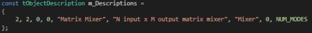
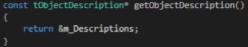
Once the object description is set, developers need to override the virtual getObjectDescription method inherited from the base class CAudioObject:
Once the object’s overall description is provided, a mode description has to be provided for every “Mode” supported by the object. This number is specified in the section above.
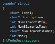
The table below provides a description of the variables required to describe each mode:
|
Member
|
Description
|
|
Label
|
The label of the mode described in the subsequent fields.
|
|
Description
|
Description of what this mode does.
|
|
NumElementsMin
|
The minimum number of elements permitted.
|
|
NumElementsMax
|
The maximum number of elements permitted.
|
|
NumElementsLabel
|
The label for the number of elements. For example, the number of elements in the Parameter Biquad block represents the number of Biquad filters within the Biquad block. This field is populated with ’Number of Biquads‘ for the Biquad block.
|
|
Mask
|
Four bits are used to indicate to GTT if it is possible to configure the audio channels and the number of elements (one for configurable):
|
The basic configuration information is written to the m_Descriptions variable in the audio object header file. The tObjectDescription structure displays all the variables necessary for configuration that are not dependent on the mode of the object.
For a mode dependent description, the tModeDescription needs to be provided. The example below describes and object that has 2 modes.
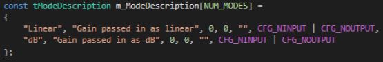
Once the mode description(s) is set, developers need to override the virtual getModeDescription method inherited from the base class CAudioObject.

Additionally, developers must implement a function for each audio object that describes the audio and control I/O, based on what they configured in the design tool. This function interacts with the object through the dll described above. The code below shows an example of this function implemented for the merger object that always has zero controls and only number of audio inputs is configurable. The number of outputs is dictated by the number of audio inputs as seen below.
xAF_Error CMergerToolbox::getObjectIo(ioObjectConfigOutput* configOut)
{
configOut->numAudioOut = m_NumAudioIn + 1;
configOut->numControlIn = 0;
configOut->numControlOut = 0;

return xAF_SUCCESS;
}
This method may rely on the following member variables depending on the object mask.
- m_NumAudioIn
- m_NumAudioOut
- m_NumElements
- m_Mode
- m_AdditionalSFDConfig
configOut is made up of the settings returned by the getObjectIo() function and is composed of:
- numAudioInputs
- numAudioOutputs
- numControlIn
- numControlOut
Advanced Design Time Configuration
Following are the advance design time configuration.
- Additional Variable Configuration
- Adding Additional Variables to Audio Object
- Audio Object description file for tuning and control
Additional Variable Configuration
Additional configuration variables are optional parameters that are needed if a specific object/algorithm needs configuration parameters beyond the default ones. Objects by default have configuration for (as mentioned above):
- Channels
- Elements
- Modes
An object can choose to utilize all the default variables or not. However, if the object needs more configuration variables, that’s where additional variables come in. A good example is parameter biquad audio object:
- Channels are used
- Elements represent number of biquads field
- Object Mode is the drop down.
However, the parameter biquad object also allows the user to select the filter topology and whether ramping is needed or not. Those two are represented with additional variables. These are fully customizable by the objects.

Adding Additional Variables to Audio Object
The object needs to inform the toolbox regarding the number of additional variables it needs. This is already described above as part of the object description. Besides the number of additional variables, the object needs to have a description of each additional variable. The audio object developer can provide the following:
Besides the number of additional variables, the object needs to have a description of each additional variable. The audio object developer can provide the following:
- Label for additional variable (example: filter enable or disable)
- Data type for the additional variable
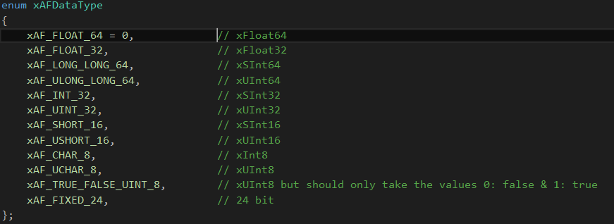
String data type is not supported, as it will add additional bytes to the flash memory. Strings are used only in GTT and not required on target.
- Defaults & Range
- Min
- Max
- Default value
- The dimension for each additional variable
- Data order – Describes how data is ordered. e.g. ascending or descending order
- Dimension description
- Label
- Size of each dimension
- Axis start index (Float always irrespective of datatype)
- Axis increment (Float always irrespective of datatype)
Starting in R release – the sizes of a dynamic additional variable (NOT the count of variables, the size of each variable) can change based on user inputs.
To enable this functionality, make sure to see the static metadata page. You must set the static metadata parameter isAddVarUpdateRequired to true.
Here are the restrictions and features:
- You can access the following members to change your size –
- m_NumElements
- m_NumAudioIn
- m_NumAudioOut
- You can only refer to these if they are true inputs (IE: you are NOT setting them in getObjectIO)
- Example : Your mask says m_NumElements and m_NumAudioOutare NOT configurable by the user (so they are considered derived values).
- You cannot utilize m_NumElements and m_NumAudioOut for changing additional var size – this would create a two way dependency as additional vars are INPUTS to getObjectIO
- You can use m_NumAudioIn freely
Below is an example of an object that has four additional variables.
| First additional variable | Second additional variable |
|
|
| Third additional variable | Fourth additional variable |
|
|
The example can be referred to here
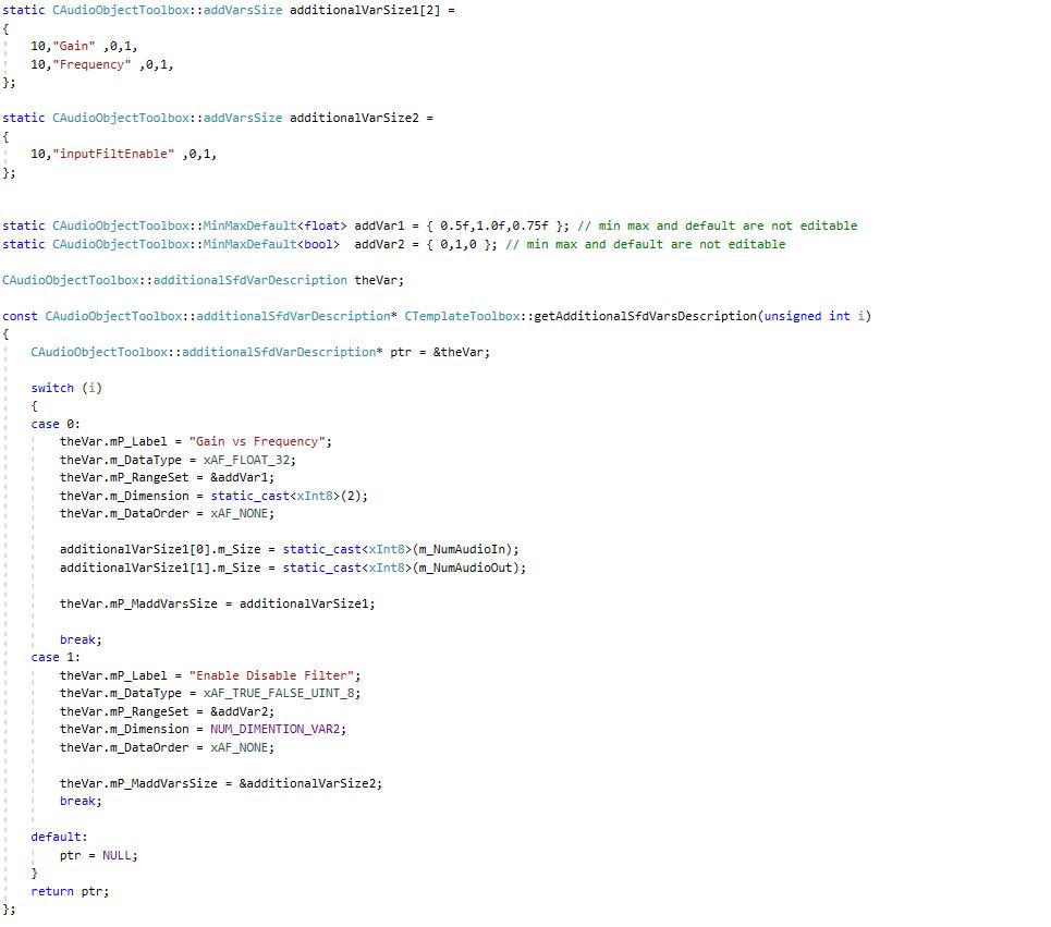
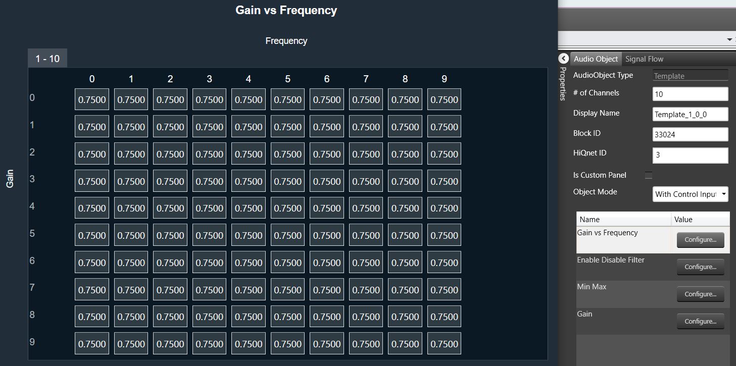
An example of the result in the SFD is shown below, with the configuration of additional variable 1:
Audio Object description file for tuning and control
Once a signal flow design is complete, SFD calls the following three Audio Object API functions, getXmlSVTemplate(), getXmlObjectTemplate(), and getXmlFileInfo(), to generate XML that describes the parameter memory layout for tuning purposes and state memory layout for control and debug purposes. This data depends on the object configuration designed in the signal flow.
These functions are enabled only when generating the XML file on a PC. The getXmlSVTemplate() function is called once and used for state variable templates, a single parameter, or control value. This state variable template can be reused in the object template or even the device description. The getXmlObjectTemplate() creates an object template that can be reused in another object template or in the device description. The getXmlFileInfo() uses the block ID assigned by the SFD and the HiQnet address of an object. HiQnet ID of the StateVariable must be unique in an object – even across hierarchical levels.
This data describes the parameter memory layout for tuning purposes and state memory layout for control purposes:
unsigned int CAudioObjectToolbox::getXmlSVTemplate(tTuningInfo* info, char* buffer, unsigned int maxLen)

{

}
unsigned int CAudioObjectToolbox::getXmlObjectTemplate(tTuningInfo* info, char* buffer, unsigned int maxLen)

{

}
unsigned int CAudioObjectToolbox::getXmlFileInfo(tTuningInfo* info, char* buffer, unsigned int maxLen)

{

}
This data must precisely describe the memory layout of the object. Here are some general guidelines:
- Each object should start with a new HiQnet block value.
- Each object should have a unique block ID value.
- Block ID refers to an entire audio object. How sub-blocks are used, depends on the object developer. This is tied to how the developer writes the tuneXTP function. For example, each sub-block in a Biquad that contains multiple filters and multiple channels, can refer to the multiple filters on one channel. Alternatively, each sub-block can refer to one filter in the Biquad.
- This file and tuning are directly related and should be implemented or laid out in the same order.
- Each parameter or state value in an object that the developer wants to expose to the user should be wrapped and described in the segment.
- Category should be set to ‘Tuning‘ for parameter memory and to ’State‘ for control memory or state memory.
To ease the generation of this data, the xAF has created XML helper functions. These functions can be used when writing getXmlSVTemplate(), getXmlObjectTemplate() functions.
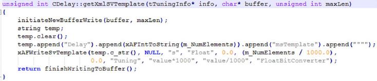
The helper function is shown below for an example where getXmlSVTemplate() for a Delay object is written using writeSvTemplate():
For more xml helper functions:
- Internal customers: Refer to XafXmlHelper.h and XafXmlHelper.cpp.
- External customers: Contact Harman.
For more information and details, please check the Device Description File specification guide.