The MIPS window presents the CPU load of cores, core objects and audio objects of the connected device.
MIPS profiling data is fetched from the device (hardware) using xTP Commands and the user can optimize signal flow based on this information.
MIPS window is enabled only when the device xAF dll version is 18.x.x.xxx or higher.
Signal flow should be flashed before launching MIPS.
MIPS profiling data of non-xAF instance core objects (Buffer,Splitter…etc) is available only from X release(24.x.x.xxxx) audio library onwards.
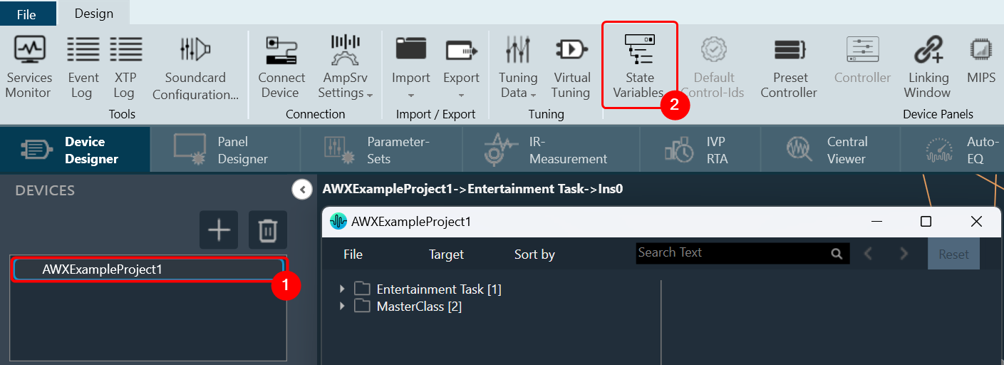
Launch MIPS Profiling
Steps to launch MIPS profiling:
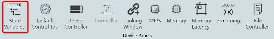
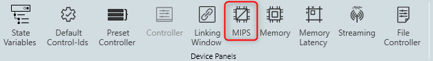
- Select the device node and click MIPS. This opens the MIPS window for the selected device.
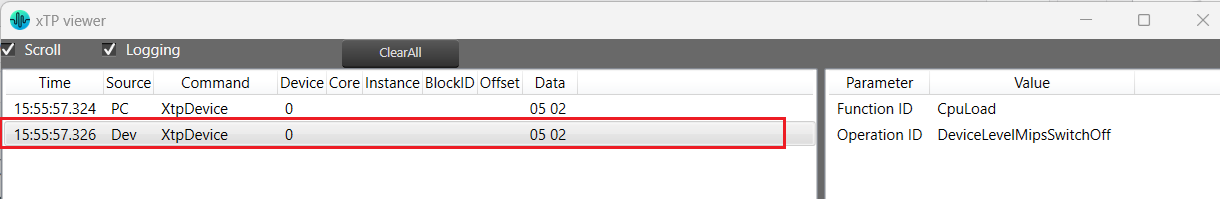
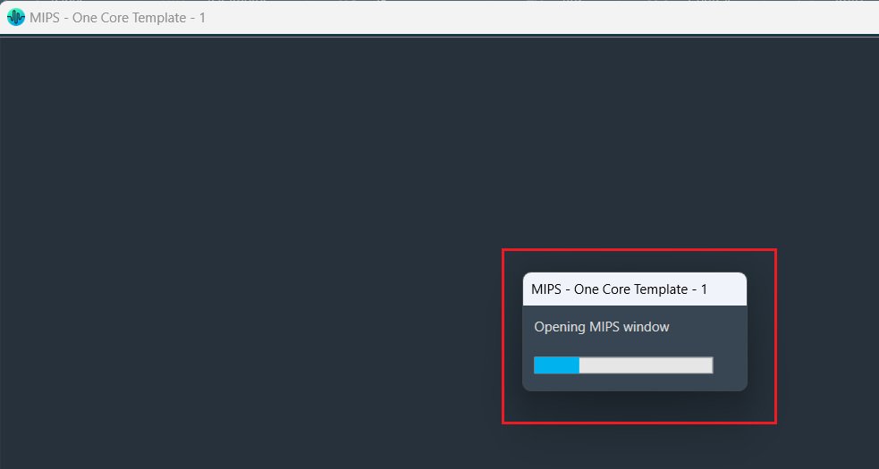
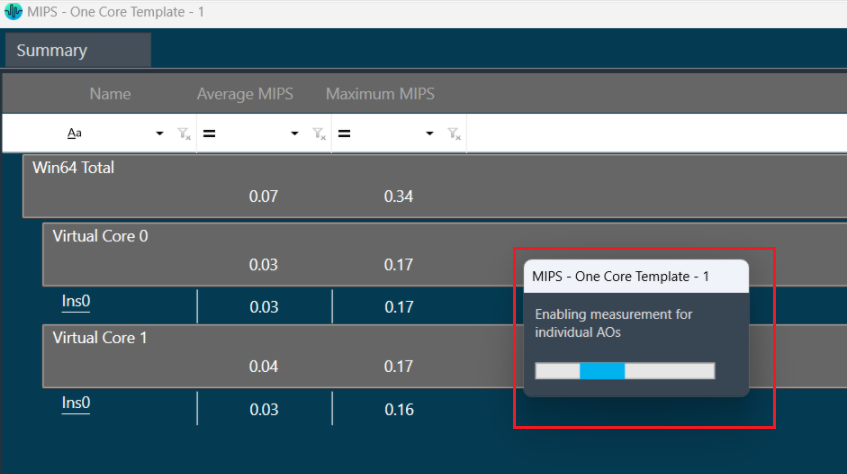
MIPS measurement on (0x64000501) and Audio Object level MIPS measurement off command (0x64000504) will be sent while opening the MIPS window and a progress window will be seen as per the below screenshot.
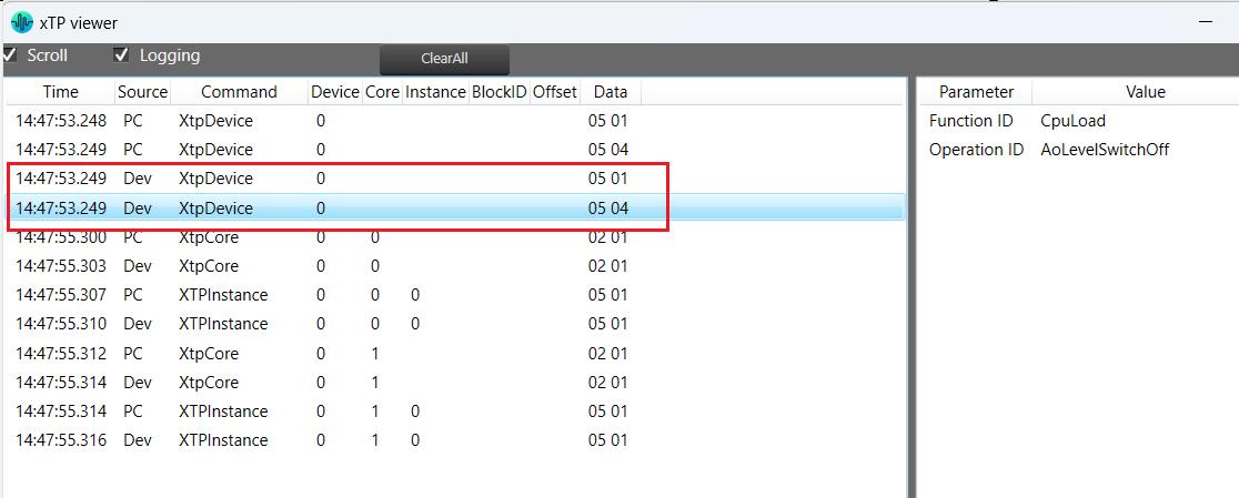
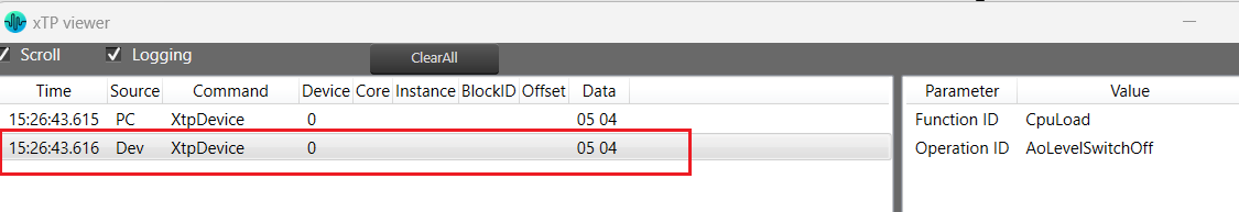
The following command will be displayed in the xTP Log Viewer.
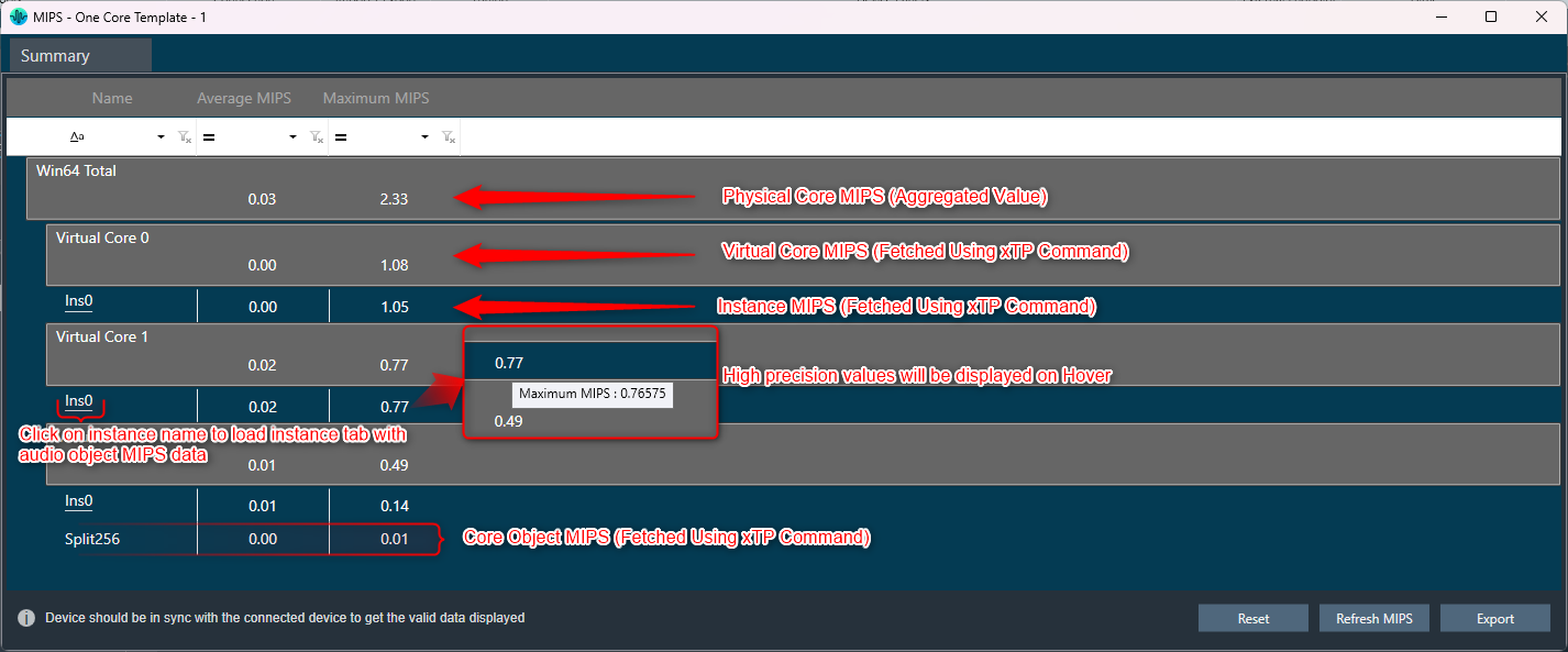
Summary Tab
- Present virtual core and core object MIPS data (Average MIPS and Maximum MIPS) retrieved from the device using the xTP Command.
- MIPS data displayed on the physical core are the aggregated values of its virtual cores.
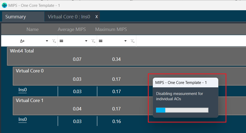
- Audio Object level MIPS measurement off command (0x64000504) will be sent while switching to the Summary tab from the Instance tab and a progress window will be seen as per the below screenshot.
Below command will be seen in xTP Log Viewer.
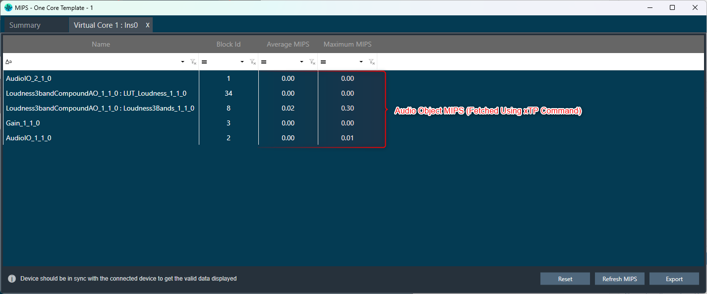
Instance Tabs
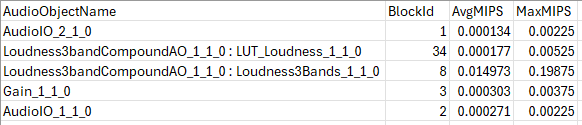
- A new tab corresponding to the selected instance will be loaded, displaying audio-object MIPS data retrieved via the xTP Command.
- Inner audio objects will be displayed alongside compound audio objects for compound audio objects.
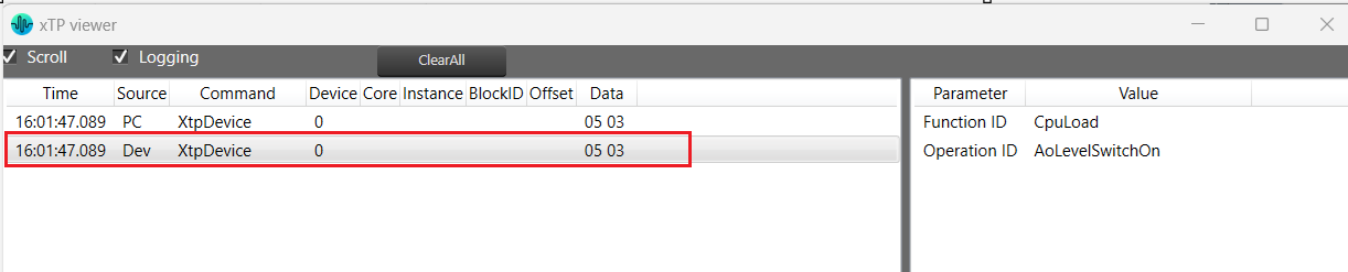
- Audio Object level MIPS measurement on command (0x64000503) will be sent while opening a new Instance tab or switching to the Instance tab from the Summary tab and a progress window will be seen as per the below screenshot.
Below command will be seen in xTP Log Viewer.
Reset
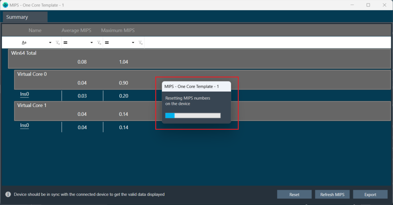
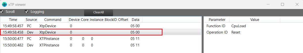
When you click the Reset option, the MIPS number for the device will get reset for the selected tab and Reset command (0x64000500) will be sent and a progress window will be displayed as per the below screenshot.
Below command will be seen in xTP Log Viewer.
Refresh MIPS: When you click the Refresh Mips option, the MIPS data for the current tab will be refreshed.
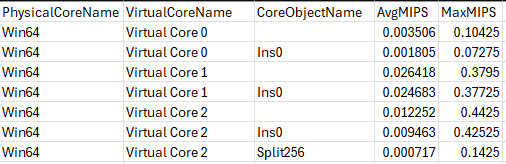
Export to CSV: When you select the Export option, the Mips data for the current tab will be exported to a CSV file. The CSV format is shown below.
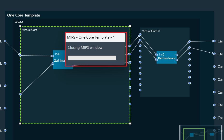
Closing MIPS Window: When you click on cross (x) to close the MIPS window, the MIPS measurement off command (0x64000502) will be sent and a progress window will be displayed as per the below screenshot.
Below command will be seen in xTP Log Viewer.