In the AudioworX Starter Kit, the Raspberry Pi 5 functions as the audio processor running the AWX Amp Application. This application receives raw audio input streams from and sends back processed audio to HiFiBerry ADC8x add-on and DAC8x HATs via the 4 stereo input audio ports and the 4 stereo output audio ports, respectively. In the rest of the document, the Raspberry Pi 5 with the HiFiBerry HATs together (the core of the Starter Kit) is referred to as the “AudioworX Starter Kit” or simply, the “Starter Kit”.
The following sections describe the hardware connections needed for a functional AudioworX Starter Kit in detail.
- Basic Starter Kit Hardware Connections
- Hardware Connections in Active Speaker Setups
- Hardware Connections in Passive Speaker Setups
- Verifying the Starter Kit Connections
Basic Starter Kit Hardware Connections
The Starter Kit can be used in both active and passive speaker setups. In both cases, the Starter Kit requires the following basic hardware connections to be made:
- Direct ethernet connection to the PC using an ethernet cable,
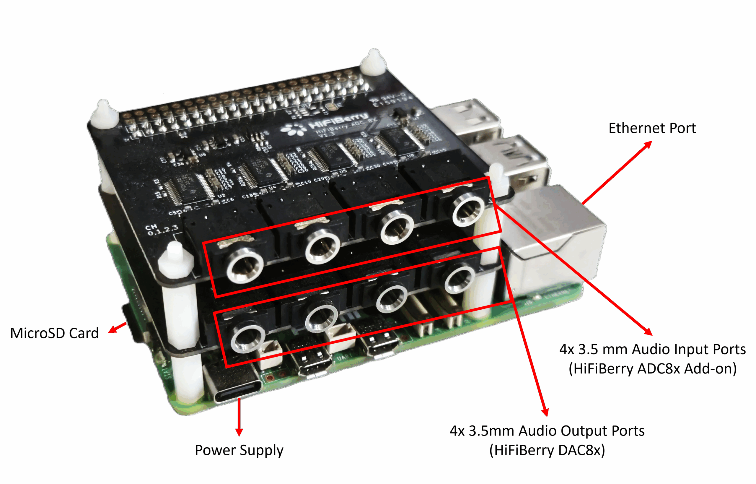
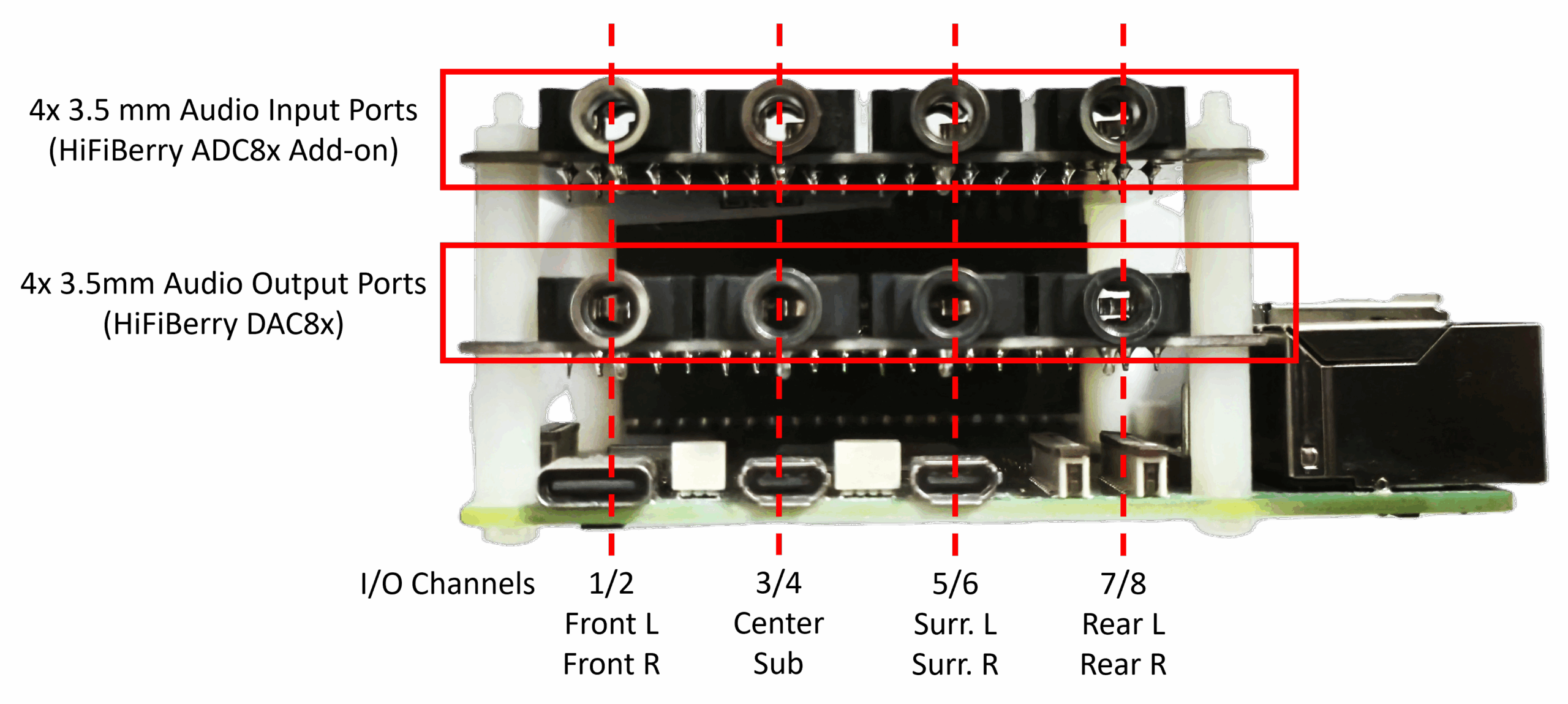
- 8-channel line audio input via the 4 stereo audio input ports (top row – HiFiBerry ADC8x Add-on) using 3.5mm connectors,
- 8-channel line audio output via the 4 stereo audio output ports (bottom row – HiFiBerry ADC8x Add-on) using 3.5mm connectors,
- The power supply.
The image below shows the Starter Kit and its connection ports.
For the Starter Kit to be fully operational, the PC and the Raspberry Pi must be accessible to each other through a Local Area Network (LAN) and the preferred mode is via direct ethernet connection as indicated in the block diagram in the active and passive speaker setup block diagrams given in the following sections.
However, in situations where a direct ethernet connection cannot be made, the Starter Kit functions as a Wi-Fi hotspot (access point) named AP_AWXStarterKit with the password “starterkithotspot” for the PC to directly connect via Wi-Fi. Refer to section “Starter Kit Configuration > Wi-Fi Config” in SKUtility Tool – Graphical Application for more details.
Hardware Connections in Active Speaker Setups
For multi-channel active speaker setups (powered speakers) on test benches or in listening rooms, the audio output channels on the Starter Kit can be directly connected to the speakers, enabling a full 7.1 speaker configuration. The below block diagram shows the hardware connections in an active speaker setup.
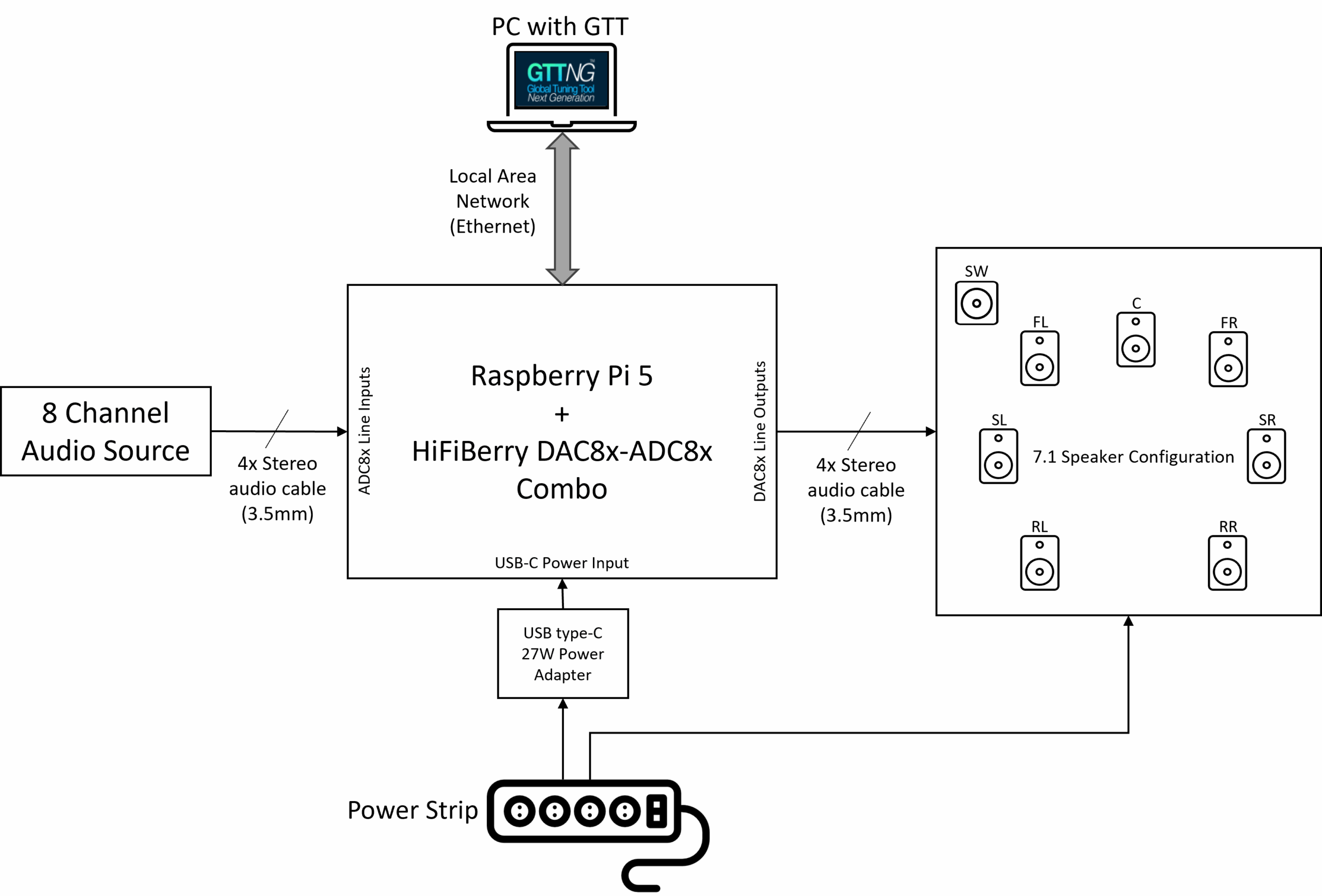
The Starter Kit has been configured by default to run the example project described in The Starter Kit Example Project. In this configuration, the audio output channels follow the 7.1 speaker configuration, and the speakers are expected to be connected to the 3.5 mm audio output ports as follows:
- Front Left and Front Right speakers to the first port,
- Center speaker and the Subwoofer to the second port,
- Surround/Side Left and Surround/Side Right speakers to the third port, and,
- Rear Left and Rear Right speakers to the fourth port.
The above diagram assumes 7.1 audio for the input ports as well (in line with The Starter Kit Example Project. Channels 1 and 2 (Front L and Front R) are typically used for a stereo input, and the rest of the channels may be used as deemed fit for the audio processing pipeline application, for example, microphones with pre-amp (since the inputs are line-level).
Generally, in a standard TRS (tip-ring-sleeve) 3.5 mm audio jack, the tip carries the left channel, and the ring carries the right channel audio. However, identifying them and connecting them to the correct speaker requires careful consideration. To simplify this, the Starter Kit example project has a Router audio object in its signal flow to route the signals correctly in software.
Hardware Connections in Passive Speaker Setups
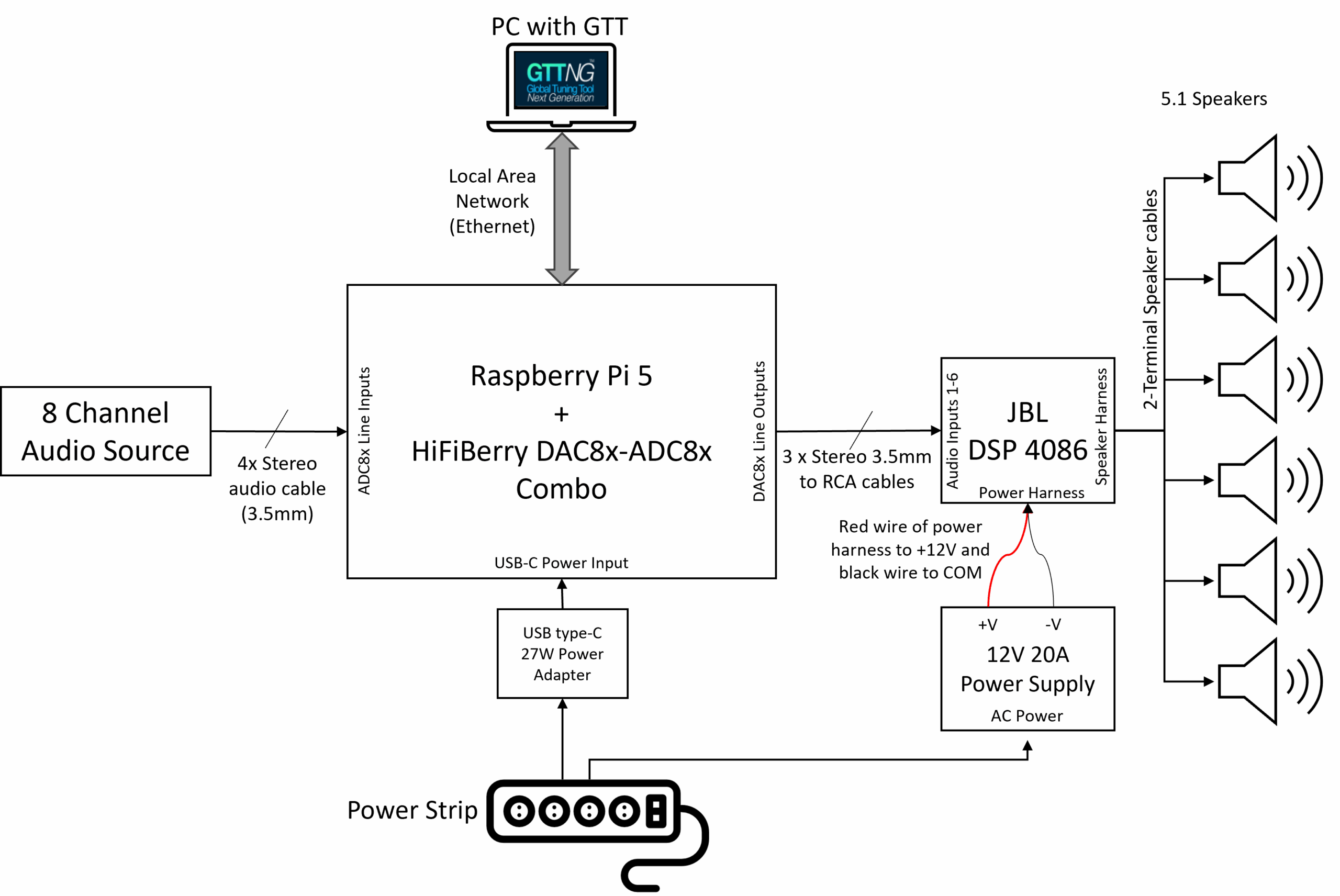
The description in this section uses the JBL DSP-4086 car audio amplifier for illustrative purpose. However, an AudioworX Starter Kit package may contain a different amplifier, may be similar in usage and specification, whose integration steps may vary.
For a multi-channel passive speaker setup like in a car, an additional power amplifier is needed since the HiFiBerry DAC8x can only output line-level signal (+4 dBu, approx. 2.1Vrms), which is insufficient to drive passive speakers in most cases.
For such systems, the Starter Kit package includes a JBL DSP-4086 car audio amplifier (or similar), a 6-input and 8-output amplifier that can drive 4Ω or 8Ω loudspeakers up to a maximum of 40W per channel. The on-board DSP in the amplifier is deliberately bypassed and the amplifier is configured to pass-through the 6 input audio channels to the first 6 output channels (the last 2 output channels are not used), with only power amplification to drive the speakers, thereby fully centralizing all audio DSP functions to the AWX Amp application in the Raspberry Pi 5.
The block diagram below shows the hardware connections for such systems.
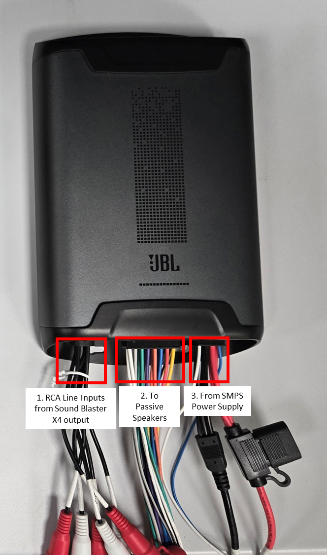
Hardware Connections for the JBL DSP-4086
The following connections are to be made at the JBL DSP-4086 amplifier end:
-
- RCA Audio Inputs from the Starter Kit (bottom row of 3.5 mm ports), using 3.5mm to RCA stereo cables:
- First output port of the Starter Kit to Channels 1 and 2 of the JBL amplifier,
- Second output port of the Starter Kit to Channels 3 and 4 of the JBL amplifier,
- Third output port of the Starter Kit to Channels 5 and 6 of the JBL amplifier.
- Speaker Harness to the passive speakers via speaker cables (each speaker output has a + and – terminal labelled on the JBL speaker harness wires):
- Channels 1 and 2 to the Front Left and Front Right speakers,
- Channels 3 and 4 to the Center and Sub-woofer speakers,
- Channels 5 and 6 to the Side Left and Side Right speakers.
- Power from the SMPS Power Supply:
- Red wire (positive power terminal) to the +V terminal of the SMPS power supply,
- Black wire (negative power terminal) to the COM terminal of the SMPS power supply,
- Blue thin wire (Remote In) to the +V terminal of the SMPS power supply.
JBL DSP-4086 Car Amplifier Connections
- RCA Audio Inputs from the Starter Kit (bottom row of 3.5 mm ports), using 3.5mm to RCA stereo cables:
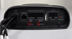
4. Ensure that the physical switches on the JBL amplifier are set to the following states:
-
- “Input Level” switch to “LO” (extreme left position),
- “Turn-on Mode” switch to “REM” (extreme left position).
The next section describes how to verify if the Starter Kit is configured properly and is functioning as expected.
Verifying the Starter Kit Connections
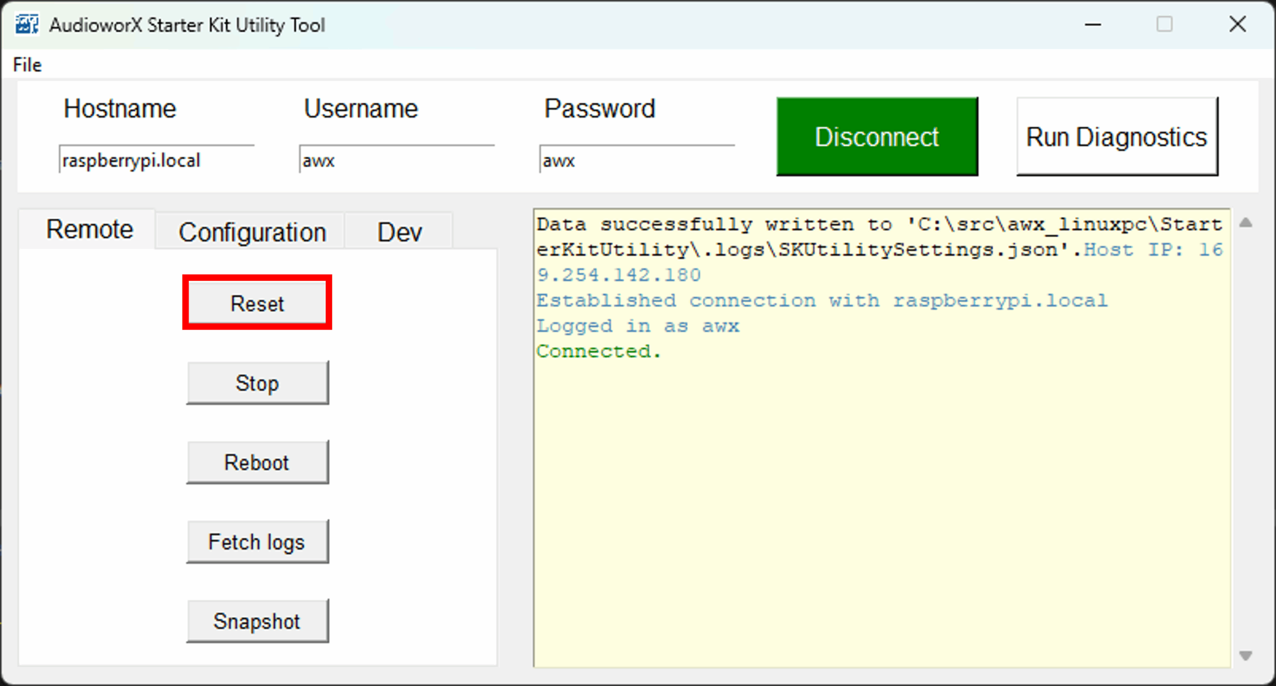
The SKUtility tool’s “Diagnostics” feature can be used to verify if the Starter Kit hardware is properly configured, connected and is functioning as expected. To run diagnostics:
- Ensure that the Starter Kit is powered on,
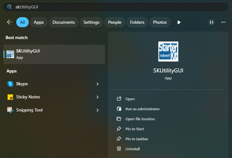
- Run the SKUtilityGUI.exe from the start-menu,
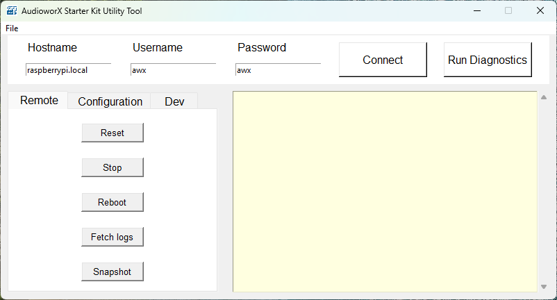
- Type in the user credentials to log into the Starter Kit (the default credentials are pre-filled as shown in the below figure).
- Press the “Run Diagnostics” button.
This will print a log in the right-hand side pane of the SKUtilityGUI as shown below.
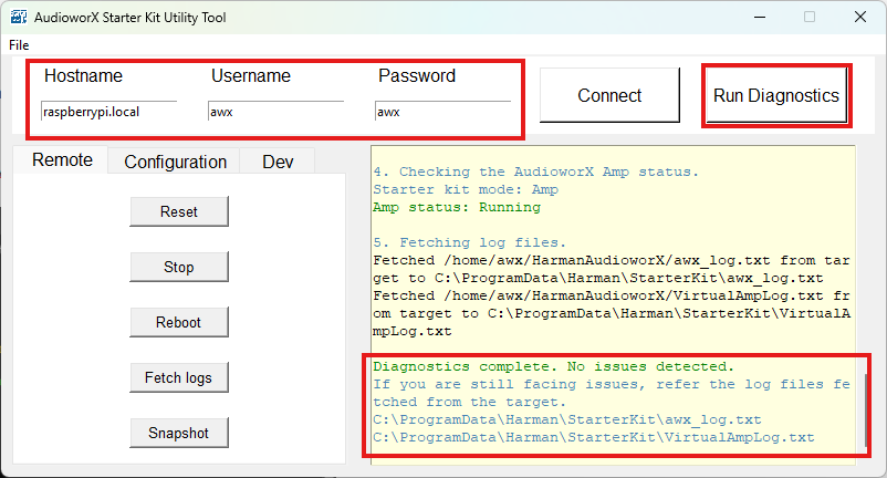
If the Starter Kit is properly configured, the text “Diagnostics complete. No issues detected.” will be displayed in the log as highlighted above. If the diagnostic detects issues with the Starter Kit, refer to Starter Kit Troubleshooting.
The SKUtility Diagnostics feature only verifies the basic configuration. Troubleshooting the speaker connections is out-of-scope for the diagnostic tool (including the amplifier connections and configuration). The most basic method for diagnosing audio output is to use a pair of headphones and manually plug it into each audio output port to verify audio output.
AudioworX Starter Kit packages received directly from Harman AudioworX contain hardware components that are pre-configured. The above instructions are sufficient to begin executing GTT workflows with the Starter Kit. If the components are purchased independently, write to Harman AudioworX support at AudioworXSupport@harman.com to receive detailed steps on configuring each component.