Memory Latency

Memory latency shows the amount of time taken by the CPU from initiating a request for assessing memory to actual reading or writing data at the requested memory.

In AudioworX, the latency of the memory request is abstracted and only measured in relative levels.

  • Level 1 – fastest memory available in the platform.
  • Level 16 – slowest.

The Memory Latency Editor provides a way to configure latency levels for individual audio object memory records from GTT.

During design time, GTT retrieves memory records for audio objects from the audio library in the following cases:

  • While adding an audio object.
  • Modifying audio object i.e changing the number of inputs, outputs, number of elements, or selected mode.
  • Modifying additional parameter value.
  • Upgrading audio object.
  • Import of project which defaults to a different dll other than the created one.
  • Upgrading device framework to version 17 dll or above.
  • The changing target type of Core.
  • Changing Sample Rate or Block Length of instance.

GTT supports Memory Latency feature only if the xAF dll version is 17.x.x.xxx or above.

Editing Memory Latency

Memory records will have default latency selected by the Audio Object developer. GTT provides the option to set the latency for every memory record of the audio object in the Memory Latency Editor.

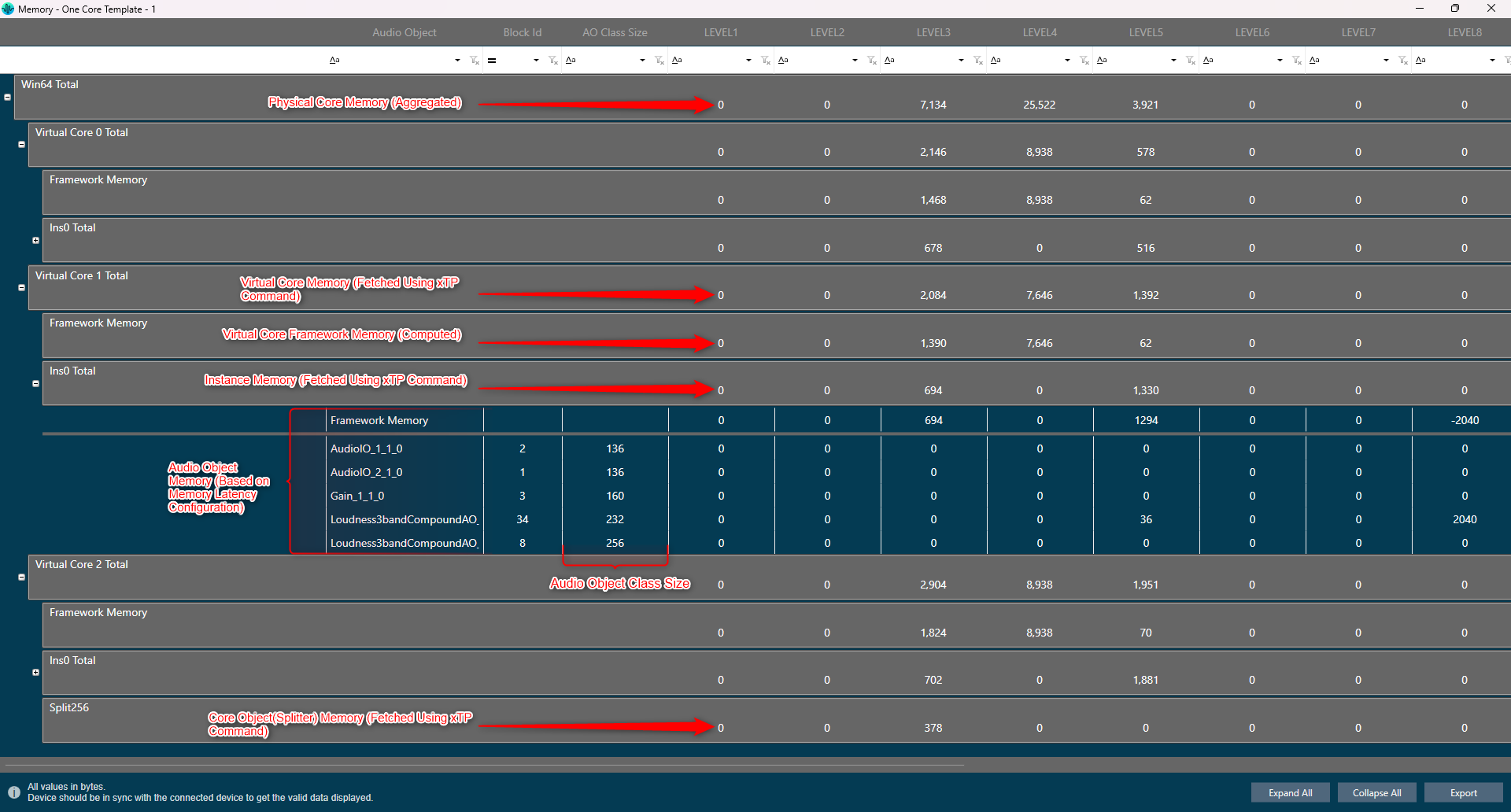
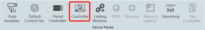
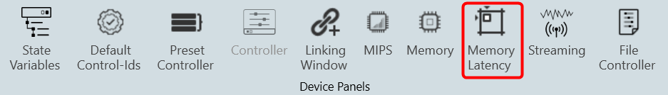
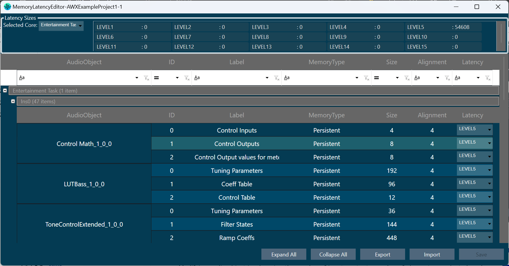
  1. Select the device node and click Memory Latency. This opens the Memory Latency window for the selected device. When the Memory window is launched, a multi-level collapsible grid with core, instance, and audio objects will be displayed.

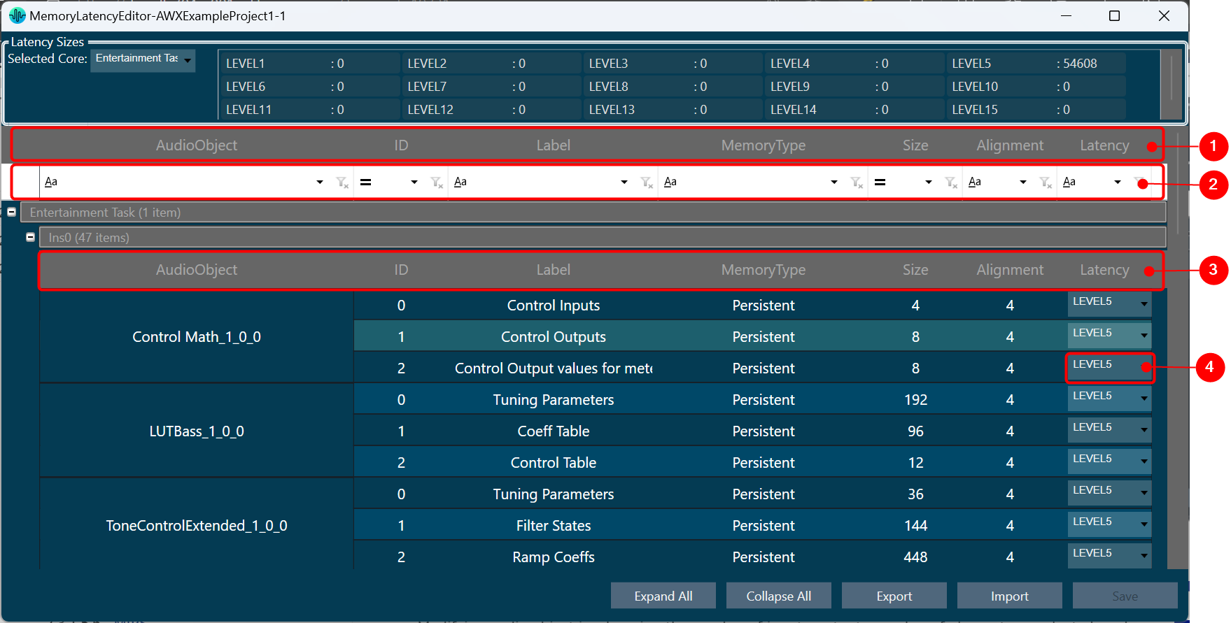
1 – Header, 2 – Column Filter, 3 – Header, 4 – Latency Sector

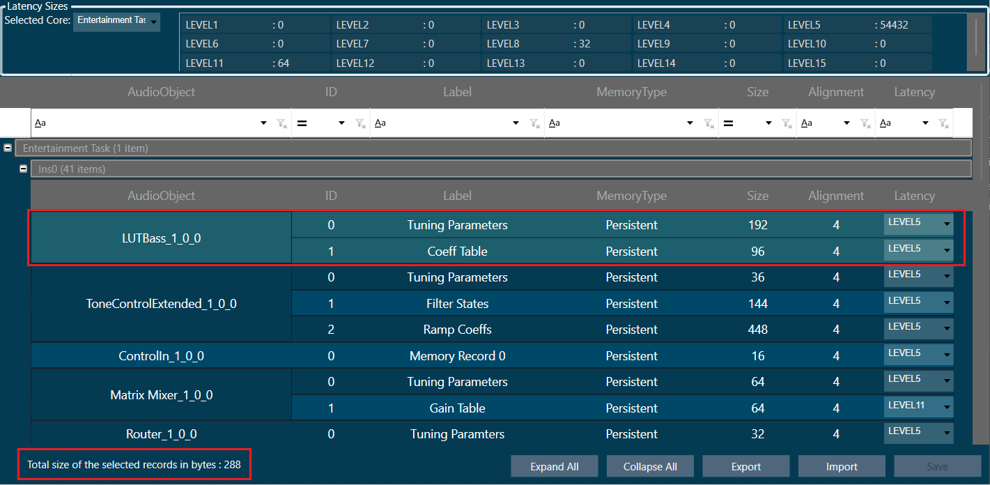
  • Multiple memory latency record selection: You can select multiple records in the memory latency window.
    • To select the specific rows – Hold Ctrl and click on the required rows. This method is useful when you want to preform action on specifics rows.
    • To select a set of row – Click on the first row of the set, hold Shift, and then select last row of the set. This method is most useful when selecting a large number of rows in a range.

Sum of all the selected memory latency record size will be shown as “Total size of the selected records in bytes” in the memory latency window.

“Total size of the selected records in bytes” will be visible only on selecting any memory latency record in the window.

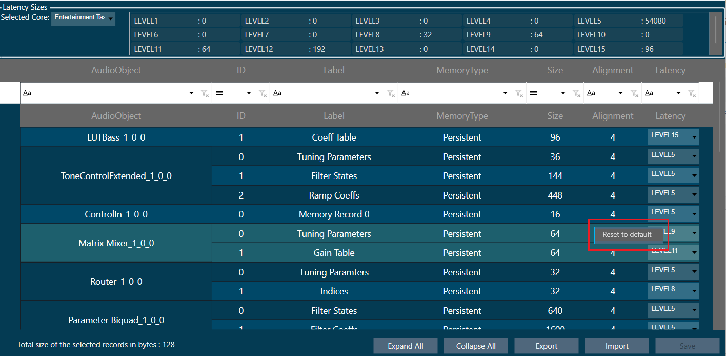
  • Reset to default latency level: You can reset the selected records to its default latency level.  Right click on selected records or anywhere on latency grid. A context menu “Reset to default” option will be displayed. Click on the “Reset to default” option, all the selected records of the latency level will be set to default value which is “LEVEL5”. Click on “Save” button and it will be saved into database.
    • To reset records to default latency level for the specific rows – Hold Ctrl, select on the required rows, and then right-click on selected records. A context menu “Reset to default” option will be displayed. Click on the “Reset to default” option.
    • To reset records to default latency level for a set of row – Click on the first row of the set, hold Shift, select last row of the set, and then right-click on selected records. A context menu “Reset to default” option will be displayed. Click on the “Reset to default” option.

  • Saving Latency memory: Only Latency can be selected. Other attributes of memory records are read-only. When you click on Save, the Latency for the memory record will be saved.

The Save Button is disabled until a change in latency is detected.

  • Send Memory Records to Device: Send Signal Flow will handle sending Memory records to the Device with a specified latency. When the signal flow send is successful, the device will boot up with the memory latency specified.
  • Import Export of Project having Memory Record: Memory latency is preserved if the export and import occur on the same xAF dll by version.
    If the dll version changes, Import will generate a new memory record based on the new target xAF dll version.
  • Copy Paste of Audio Object or Core Object Containing Memory Latency: If the properties of the source and targets are the same, memory latency is retained in the pasted object.
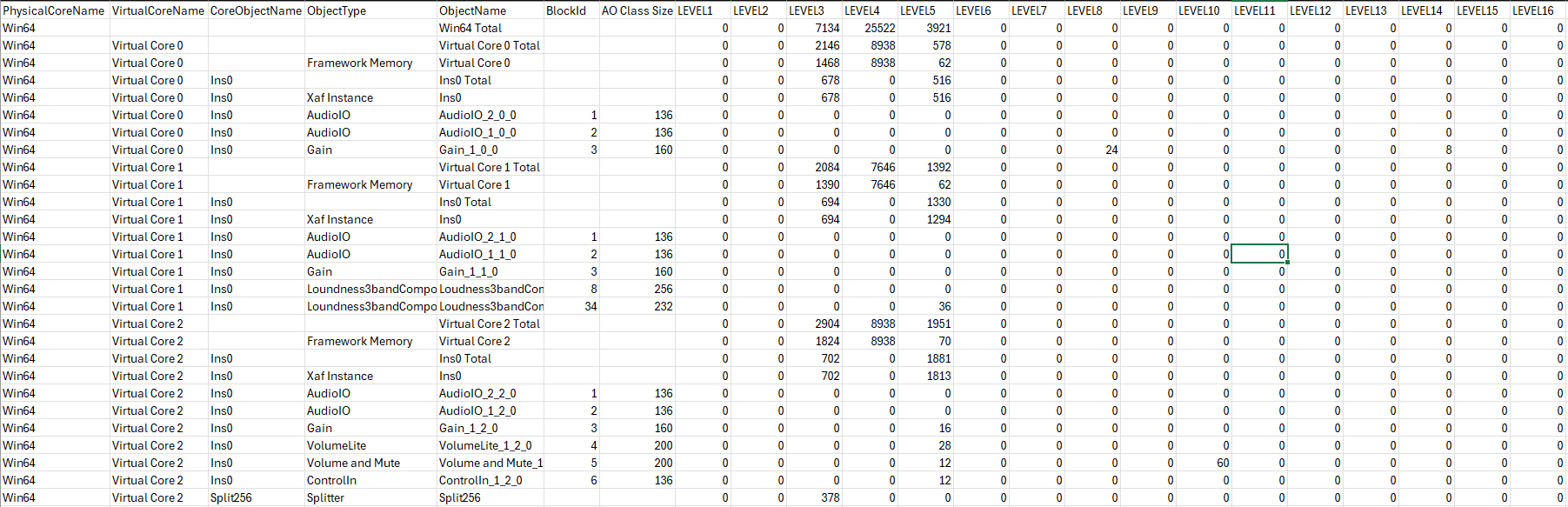
  • CSV Import/Export: You can export and import of memory map to CSV files. The primary operation of this feature is to export memory latency to CSV, adjust memory levels, and then import the updated memory levels back into the GTT. When the memory map form file does not match the one in GTT, GTT will request permission to import only the items that match.

Memory

The Memory window presents the CPU memory of cores, core objects and audio objects of the device in a single multi-level grid.

Memory profiling data of cores and core object is fetched from the device (hardware) using xTP Commands, and the memory of the audio object is fetched based on its memory latency configurations.

Overhead Memory consumed by core and instance is calculated and displayed as ‘Framework Memory’. You can optimize signal flow or adjust latency based on this information.

Apart from memory profiling data, the class size of each audio object is also fetched from the device using xTP commands and displayed in the memory window from the X release(24.x.x.xxxx) audio library onwards.

Memory window is only enabled if the device xAF dll version is 18.x.x.xxx or higher.

Before starting the Memory window, the signal flow should be flashed.

If the memory latency configuration is updated, the signal flow should be flashed again and the memory window should be restarted.

Memory profiling data of non-xAF instance core objects (Buffer,Splitter…etc) is available only from the X release(24.x.x.xxxx) audio library onwards.

Launch Memory Profiling

Steps to launch Memory profiling:

  1. Select the device node and click Memory. This opens the Memory window for the selected device.

When the Memory window opens, it will show a collapsible grid with core, instance, and audio objects.

  • The physical core memory values displayed are the sum of its virtual cores.
  • xTP Commands retrieve virtual core and core object memory from the device.
  • Memory latency configurations are used to fetch audio-object memory.
  • Overhead Memory consumed by the core and instance is calculated and displayed as ‘Framework Memory’.
  • xTP Commands are used to retrieve audio object class size based on the block ID of the audio object.

  • Expand All: Expands all rows of the collapsible grid.
  • Collapse All: Collapses all rows of the collapsible grid.
  • Export to CSV: Click on the Export option to export the memory data of the device in a CSV file.  The exported file will have a row for Framework Memory for Virtual core, Instance, Audio Objects, and Physical core along with columns PhysicalCoreName, VirtualCoreName, CoreObjectName, ObjectType, ObjectName, BlockId, AO Class Size and Level1 to Level 16 as per the below image.

MIPS

The MIPS window presents the CPU load of cores, core objects and audio objects of the connected device.

MIPS profiling data is fetched from the device (hardware) using xTP Commands and the user can optimize signal flow based on this information.

MIPS window is enabled only when the device xAF dll version is 18.x.x.xxx or higher.

Signal flow should be flashed before launching MIPS.

MIPS profiling data of non-xAF instance core objects (Buffer,Splitter…etc) is available only from X release(24.x.x.xxxx) audio library onwards.

Launch MIPS Profiling

Steps to launch MIPS profiling:

  1. Select the device node and click MIPS. This opens the MIPS window for the selected device.
    MIPS measurement on (0x64000501) and Audio Object level MIPS measurement off command (0x64000504) will be sent while opening the MIPS window and a progress window will be seen as per the below screenshot.

The following command will be displayed in the xTP Log Viewer.

Summary Tab

  • Present virtual core and core object MIPS data (Average MIPS and Maximum MIPS) retrieved from the device using the xTP Command.
  • MIPS data displayed on the physical core are the aggregated values of its virtual cores.
  • Audio Object level MIPS measurement off command (0x64000504) will be sent while switching to the Summary tab from the Instance tab and a progress window will be seen as per the below screenshot.

Below command will be seen in xTP Log Viewer.

Instance Tabs

  • A new tab corresponding to the selected instance will be loaded, displaying audio-object MIPS data retrieved via the xTP Command.
  • Inner audio objects will be displayed alongside compound audio objects for compound audio objects.
  • Audio Object level MIPS measurement on command (0x64000503) will be sent while opening a new Instance tab or switching to the Instance tab from the Summary tab and a progress window will be seen as per the below screenshot.

Below command will be seen in xTP Log Viewer.

Reset

When you click the Reset option, the MIPS number for the device will get reset for the selected tab and Reset command (0x64000500) will be sent and a progress window will be displayed as per the below screenshot.

Below command will be seen in xTP Log Viewer.

Refresh MIPS: When you click the Refresh Mips option, the MIPS data for the current tab will be refreshed.

Export to CSV: When you select the Export option, the Mips data for the current tab will be exported to a CSV file. The CSV format is shown below.

Summary Tab
Instance Tab

Closing MIPS Window: When you click on cross (x) to close the MIPS window, the MIPS measurement off command (0x64000502) will be sent and a progress window will be displayed as per the below screenshot.

Below command will be seen in xTP Log Viewer.

Link Window

The Linking Window is designed to assist you by reducing the number of audio parameter configurations. It enables you to organize the filters and channels. When you set one item in a group, the remaining items in the group will have the same value.

By default, all the groups link are enabled. If you want to disable the specific group link, click on the toggle button to disable it.  GTT will store the group linking status in project file.

If you want to disable all the groups link, select the Disable Linking checkbox.

Create a New Group

Steps to create a new group:

  1. Open Linking Window, expand the task, and drag-drop the object to the right-side section under Groups. A new group is created, expand the new group. Under the new group, you can view the added object.

Renaming Groups: Double-click on a group name to rename it.

Only groups can be renamed; Audio objects cannot be renamed.

Removing Objects: Click on the remove icon to remove the object. This will also delete all child objects.

Removing Groups: Click the remove icon to the right of the group. This will also delete all child objects.

Add Object to Existing Group

Steps to add object to an existing group:

  1. Open Linking Window, expand the task, and drag-drop the object to the right-side section under target group. A new group is created, expand the new group. Under the new group, you can view the added object.

If an object cannot be added to a specific group, the color of that group will change to grey.

If the object is added to the group, the color of the group will change to blue.

Linking Rules

  • Each of the audio objects can be part of only one group.
  • If a child audio object is part of a group, the parent element cannot be part of that group.
  • Groups can contain only one type of audio object. For example, you cannot link a Biquad with a Delay. Each group can contain more than one AO.
  • Objects in groups are linked according to their order. For example, if you link two EQ channels, the first Biquad from the first channel will be linked with the first Biquad from the second channel.
  • Changing links is done live. You do not need to close the window for the changes to be working.

Controller

The controller window is used to send instance commands.

The controller feature is enabled only when the device xAF dll version is lower than 18.x.x.xxx.

Steps to setup controller:

  1. Enter a valid Core Id and Instance Id and click on Get Status to get the current available slot of the device. The response from the device will be displayed in the Response section.
  2. Click Save to save the current instance data on the device to the memory slot entered.
  3. Click Load to load the data from the memory slot to the device RAM.

If there is any error in the device connection or if any invalid Core Id and/or Instance Id were entered, the error message “Request failed!!!! Please make sure […]” will be displayed.

Configuring Preset Controller

The preset controller is the central place for managing and organizing how you will load presets in your signal flow.  It also contains other related features such as creating .set files, storing sets, and recalling sets of parameter sets available.
A “Slot” is a group of parameters set one level above. You can create multiple such slots and do any actions like create set files, store , recall etc.
In addition to GTT functionalities, it is also possible to send Xtp commands to device. There are XTP commands to send slot map and Load the slot on to device. You need to export all .set files and manually flash on to the amp.

To know more about  the Preset Controller functionality, refer to below topics.

Limitations in Preset Controller

  • After the set map is configured, if parameter sets are deleted, a generic sets window should be reopened to see the changes.
  • Generic sets window can be opened only one at a time. If a new window has to be opened for a new device, the currently opened window will be automatically closed (changes made will be retained).
  • Parameter sets are project specific. Generic sets are device-specific.
  • Only basic validations are done. Illegal values are yet to be handled. Ex: Entering a string value for fade in –out is considered illegal and will not be handled.
  • Signal flow and presets saved on the device should be in sync.
  • The slot map and set files export is offline. The user shall make sure that these files are in sync with GTT for better visualization.
  • All the presets configuration, slot map, and preset data are sent together in “Send To Device”. There is no option to send these data individually.
  • For any changes in presets or maps, the user is expected to send all data (config, map, and presets).

Virtual device naming conventions. The set files should always follow the “preset [preset id]” naming convention. Example preset0, preset1, etc. when checkbox “Maintain Folder Structure” is unchecked.

When exporting the slot map file for Virtual Device usage, the name should always be sect262144.flash.

If set groups overlap for a given audio object, the one loaded last will override the first.  The order is not guaranteed so it is not recommended to do this.

Exploring GTT Workspace

The GTT workspace consists of several tabs, including the Home screen, Device Designer, Panel Designer, and Parameter Sets. Additionally, there are specialized tabs for tasks such as IR Measurements, IVP RTA, Central Viewer, Auto EQ, and AI Module. This guide focuses on providing information about the Home screen, Device Designer, Panel Designer, and Parameter Sets tabs.

Related Topics

Device Designer Overview

The Device Designer comprises of various tools and interfaces that are used to create and run audio processing systems on hardware. The Device Designer contains the canvas and modules needed to create the signal processing template, while the SFD interface handles most of the target and audio object interactions.

When you launch a project in GTT, the Device Designer screen appears, which includes the following elements:

  1. Ribbon and Group: The ribbon is composed of six groups, each of which represents a subset of program functionality. In addition to these programs, there are also additional contextual programs that automatically appear depending on what is currently selected.
    The GTT ribbon comprises six groups: Tools, Connection, File, Tuning, Device Panels, and External Endpoints. Each group has specific tools of related functions. It gives you quick access to the tools and functions you need to complete a task.

    • Tools: This group includes three tools: Services Monitor, Event Log, and xTP Log. The event log and xTP log in GTT can both be checked and monitored using all these tools.
    • Connection: This group includes tools to set up the connection between the physical or virtual device, such as configuring socket connections and port settings. Additionally, it facilitates you to establish the connection once it has been configured.
    • Import/Export: This group allows you to import and export device files, tuning data files, device description data files, and corporate pin data.
    • Tuning: This group includes Tuning Data and Virtual Tuning. Using Tuning Data, you can open and tune the audio files. Virtual Tuning enables the measurement of impulse responses of an acoustic environment using the AudioworX measurement Module.
    • Device Panels: This group includes the following tools: State Variables, Default Control-Ids, Present Controller, Controller, Linking Window, Mips, Memory, Memory Latency, Streaming, and File Controller. Each of these tools is equipped with a unique set of functions.
    • External Endpoints: This feature allows external tuning to communicate with the device. The GTT will receive the requests from external tuning tools and send them to the device via GTT. This is made possible by a WCF service endpoint that third-party tools can access.
  2. Devices List: This section displays the list of projects. In addition, you can add and delete a device.
  3. Toolbox: This section display core levels of processing, such as block length conversion, merger/splitter, and sample rate conversion within the audio processing pipeline.
  4. Device Operations: This section contains several functions related to physical/virtual devices like Load Device Config, Edit Device, Send Device Config, Send Signal Flow, Export SFD, and Control Ids.
  5. Properties Panel: A Device Template is a combination of three layers – Physical Layer, Virtual Core, and Core Object. When you select one of the cores, the properties of the core are displayed on the right side. If required you can modify the core properties.
  6. Device View: The workspace is used to add devices and program the device core. You can use the magnifier function to adjust and change the size of the design workspace.

Tuning

Tuning Data

You need to connect a device to GTT to send/receive tuning or state data.

When the device is connected you will get the following options.

  • Send Tuning Data
  • Receive Tuning Data
  • Receive State Data

Virtual Tuning

This feature will be removed in the future Global Tuning Tool release.

Virtual Tuning allows you to measure impulse responses of an acoustic environment using the AudioworX Measurement Module. Based on these measurements, a production signal flow can be virtually tuned.

For this purpose, two new audio objects are implemented in AudioworX:

  • IppMimoConvolver
  • Time Multiplexer

IppMimoConvolver: The IppMimoConvolver audio object provides MIMO convolution with FIR filters using the Intel Integrated Performance Primitives (IPP) library, a multi-threaded software library of multimedia and data processing applications. It is highly optimized for various Intel® architectures and is a comprehensive library of out-of-the-box, domain-specific functions. The library is available for the Linux, MacOS, Windows and Android operating systems.

In the SFD, you can select the following object parameters at design time:

  • Number of input channels
  • Number of output channels
  • Number of taps of filters

Tuning: For each filter combination in IppMimoConvolver, this object exposes these one tuning parameters set to the GTT

  • Coefficients: The coefficients of the filters can be imported from .csv files. The filter taps that are set in the GTT must match the taps of the filter that is imported from the .csv file.

Filter coefficients can also be loaded directly from a Measurement Module session that has been pre-measured in AudioworX.

Time Multiplexer: The Time Multiplexer combines multiple input audio signals into a single audio signal by dividing the input channels into equal fixed length time slots and mixing them into a common output channel with fading between channels.

The length of the time slots and the fading characteristics can be configured at runtime.

The output signal is the signal of one input channel at a time. The next input channel becomes the first input channel again when the last input channel is reached. Depending on the fading mode, there might be a block length of fading between 2 channels.

In the SFD, you can select the following object parameters at design time:

  • Number of input channels

Tuning: This audio object exposes four tuning parameters to the GTT.

  • Mode: The mode can be set to:
    • Normal Mode: Performing multiplexing
    • Active Channel Mode: Single channel passed to the output
    • Off: No output
  • Multiplex number of blocks : Only evaluated in “Normal mode”. It presents a number of blocks (block length) after which to switch to the next input.
  • Fading mode: Only evaluated in “Normal mode”. It sets a type of fading method:
    • Cosine square fading
    • Linear fading
    • No fading (hard switch)
  • Active channel
    • If in mode “Active channel mode” – The channel number of the input channel that will be routed to the output channel.
    • If in mode “Normal mode” – Set the selected channel as current input and continue with the next channel in normal/multiplex mode after the configured number of blocks.

Virtual Tuning Configuration Prerequisites

The steps listed below describe how to configure an IppMimoConvolver object using GTT.

  1. Create a signal flow with the IppMimoConvolver object with m inputs, n outputs, and j number of taps for filters.
  2. Create a measurement with n mics and m speakers.
  3. Adjust measurement length, sample rate, etc to get exactly the required amount of coefficients (ir data points) before starting measurement.

Once the above steps are done, select the device (which contains a mimo object) from the device list to activate the device tab.

Steps to launch Virtual Tuning:

  1. Select a device, and click Virtual Tuning. This opens the Virtual tuning configuration screen.
    Graphical user interface, text Description automatically generated

Apply Coefficients to Virtual Tuning

Steps to apply coefficients to Virtual Tuning:

  1. Open Virtual Tuning and select suitable Measurement Session.
  2. Select Convolution Object to which the Coefficients to be applied.
  3. Click Apply.

The selected measurement’s IRData is retrieved and applied to the convolver object. A toast message appears, stating that the coefficients were successfully applied.
Graphical user interface, text, application Description automatically generated

Virtual Tuning Panel: The IppMimoConvolver panel is used to view the coefficients assigned to the object. This panel provides the following functions.

  • Flat
  • Import
  • Export
  • Import All

Import and Export

Import

  • Tuning Data: Use this option to import an existing tuning file (*.set or *.setr).

Users can use the following hints to see if the “imported tuning file” has made any changes to the device:

  • Check the State Variable Explorer to see if the values of the corresponding state variables have changed.
  • If the device and GTT are in sync, sending tuning data should cause the frequency response to change.
  • The user can manually create a set column to obtain the current state of the state variables after importing the tuning data file on the device.
  • The user can use the set column that is already present after importing the tuning data file on the device and pressing the “store” button. If the set column in the set file contains state variables, the user can view the modifications.

Export

  • Tuning Data: Use this option to export a tuning file (*.set or *.setr).

This method creates a .set file which contains all the object tuning data, that includes all of the device’s state variables. For example, if certain objects are not tuned, their default tuning values will be exported to the set file.

  • Export DDF Data: Use this option to export a device description data file (*.ddf ).
  • Export Control Pin Data: Use this option to export Control Pin Data (*.csv).

If no configured control pin data is available its shows the message “Control pin not configured for device”.

  • Device Template: Use this option to save device template file  (*.flash).

Important

The Device File option is hidden by default.

Steps to make Device File option visible under in Import/Export option:

1. Go to GTT installation path and locate GlobalTuningTool.exe.Config file.

Location: C:Program FilesHarmanHarmanAudioworXtoolsGTT

2. Open the file in any text editor (notepad) and update “AudioObjectDeveloperMode” attribute under “appSettings” node as shown below.

3. Set Value = true to enable Device File option. Similarly, set Value = false to disable Device File option.

Restart the GTT to take effect of updated setting.