Device Designer Overview

The Device Designer comprises of various tools and interfaces that are used to create and run audio processing systems on hardware. The Device Designer contains the canvas and modules needed to create the signal processing template, while the SFD interface handles most of the target and audio object interactions.
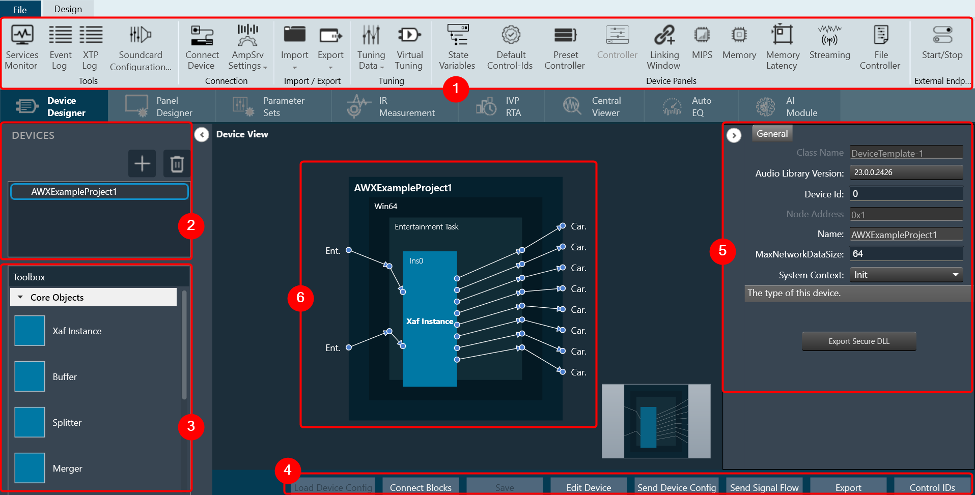
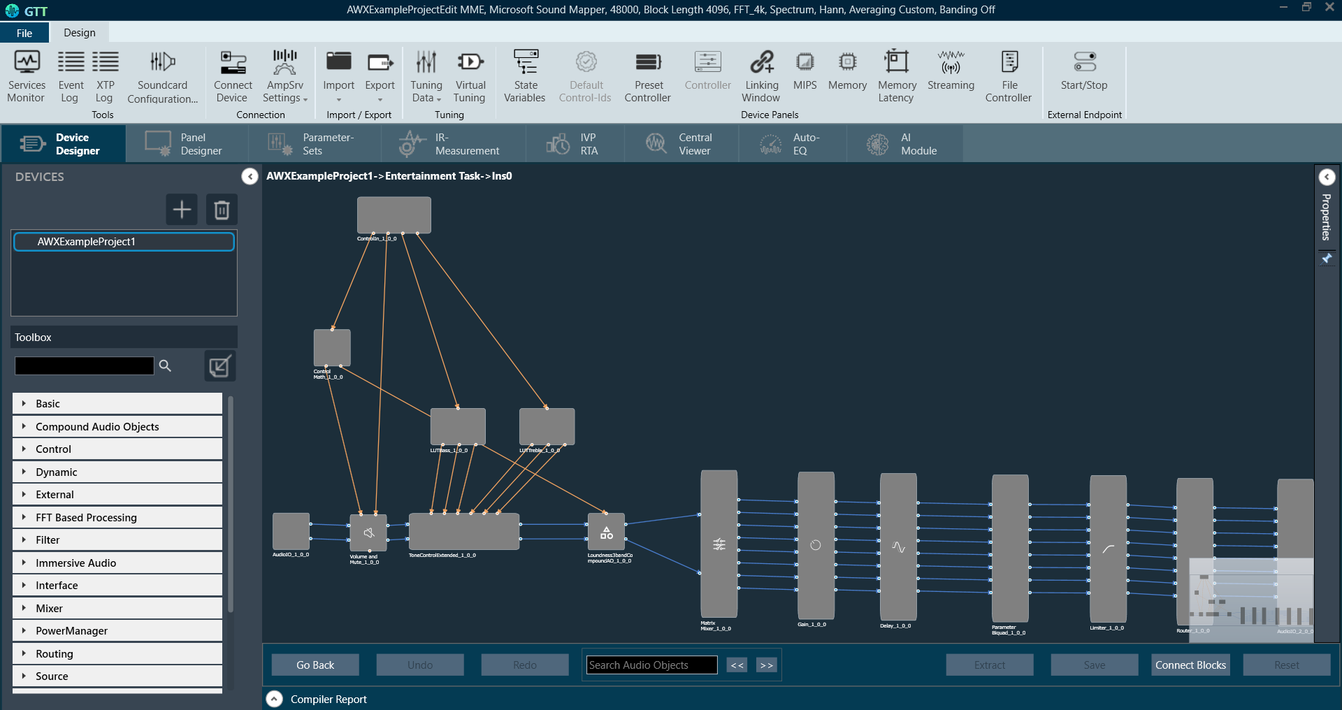
When you launch a project in GTT, the Device Designer screen appears, which includes the following elements:

  1. Ribbon and Group: The ribbon is composed of six groups, each of which represents a subset of program functionality. In addition to these programs, there are also additional contextual programs that automatically appear depending on what is currently selected.
    The GTT ribbon comprises six groups: Tools, Connection, File, Tuning, Device Panels, and External Endpoints. Each group has specific tools of related functions. It gives you quick access to the tools and functions you need to complete a task.

    • Tools: This group includes three tools: Services Monitor, Event Log, and xTP Log. The event log and xTP log in GTT can both be checked and monitored using all these tools.
    • Connection: This group includes tools to set up the connection between the physical or virtual device, such as configuring socket connections and port settings. Additionally, it facilitates you to establish the connection once it has been configured.
    • Import/Export: This group allows you to import and export device files, tuning data files, device description data files, and corporate pin data.
    • Tuning: This group includes Tuning Data and Virtual Tuning. Using Tuning Data, you can open and tune the audio files. Virtual Tuning enables the measurement of impulse responses of an acoustic environment using the AudioworX measurement Module.
    • Device Panels: This group includes the following tools: State Variables, Default Control-Ids, Present Controller, Controller, Linking Window, Mips, Memory, Memory Latency, Streaming, and File Controller. Each of these tools is equipped with a unique set of functions.
    • External Endpoints: This feature allows external tuning to communicate with the device. The GTT will receive the requests from external tuning tools and send them to the device via GTT. This is made possible by a WCF service endpoint that third-party tools can access.
  2. Devices List: This section displays the list of projects. In addition, you can add and delete a device.
  3. Toolbox: This section display core levels of processing, such as block length conversion, merger/splitter, and sample rate conversion within the audio processing pipeline.
  4. Device Operations: This section contains several functions related to physical/virtual devices like Load Device Config, Edit Device, Send Device Config, Send Signal Flow, Export SFD, and Control Ids.
  5. Properties Panel: A Device Template is a combination of three layers – Physical Layer, Virtual Core, and Core Object. When you select one of the cores, the properties of the core are displayed on the right side. If required you can modify the core properties.
  6. Device View: The workspace is used to add devices and program the device core. You can use the magnifier function to adjust and change the size of the design workspace.

Tuning

Tuning Data

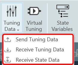
You need to connect a device to GTT to send/receive tuning or state data.

When the device is connected you will get the following options.

  • Send Tuning Data
  • Receive Tuning Data
  • Receive State Data

Virtual Tuning

This feature will be removed in the future Global Tuning Tool release.

Virtual Tuning allows you to measure impulse responses of an acoustic environment using the AudioworX Measurement Module. Based on these measurements, a production signal flow can be virtually tuned.

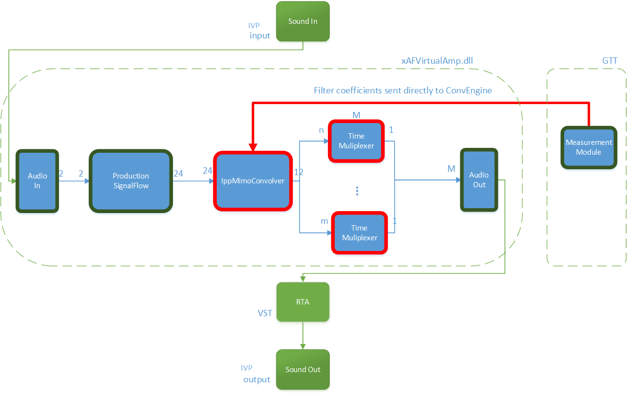
For this purpose, two new audio objects are implemented in AudioworX:

  • IppMimoConvolver
  • Time Multiplexer

IppMimoConvolver: The IppMimoConvolver audio object provides MIMO convolution with FIR filters using the Intel Integrated Performance Primitives (IPP) library, a multi-threaded software library of multimedia and data processing applications. It is highly optimized for various Intel® architectures and is a comprehensive library of out-of-the-box, domain-specific functions. The library is available for the Linux, MacOS, Windows and Android operating systems.

In the SFD, you can select the following object parameters at design time:

  • Number of input channels
  • Number of output channels
  • Number of taps of filters

Tuning: For each filter combination in IppMimoConvolver, this object exposes these one tuning parameters set to the GTT

  • Coefficients: The coefficients of the filters can be imported from .csv files. The filter taps that are set in the GTT must match the taps of the filter that is imported from the .csv file.

Filter coefficients can also be loaded directly from a Measurement Module session that has been pre-measured in AudioworX.

Time Multiplexer: The Time Multiplexer combines multiple input audio signals into a single audio signal by dividing the input channels into equal fixed length time slots and mixing them into a common output channel with fading between channels.

The length of the time slots and the fading characteristics can be configured at runtime.

The output signal is the signal of one input channel at a time. The next input channel becomes the first input channel again when the last input channel is reached. Depending on the fading mode, there might be a block length of fading between 2 channels.

In the SFD, you can select the following object parameters at design time:

  • Number of input channels

Tuning: This audio object exposes four tuning parameters to the GTT.

  • Mode: The mode can be set to:
    • Normal Mode: Performing multiplexing
    • Active Channel Mode: Single channel passed to the output
    • Off: No output
  • Multiplex number of blocks : Only evaluated in “Normal mode”. It presents a number of blocks (block length) after which to switch to the next input.
  • Fading mode: Only evaluated in “Normal mode”. It sets a type of fading method:
    • Cosine square fading
    • Linear fading
    • No fading (hard switch)
  • Active channel
    • If in mode “Active channel mode” – The channel number of the input channel that will be routed to the output channel.
    • If in mode “Normal mode” – Set the selected channel as current input and continue with the next channel in normal/multiplex mode after the configured number of blocks.

Virtual Tuning Configuration Prerequisites

The steps listed below describe how to configure an IppMimoConvolver object using GTT.

  1. Create a signal flow with the IppMimoConvolver object with m inputs, n outputs, and j number of taps for filters.
  2. Create a measurement with n mics and m speakers.
  3. Adjust measurement length, sample rate, etc to get exactly the required amount of coefficients (ir data points) before starting measurement.

Once the above steps are done, select the device (which contains a mimo object) from the device list to activate the device tab.

Steps to launch Virtual Tuning:

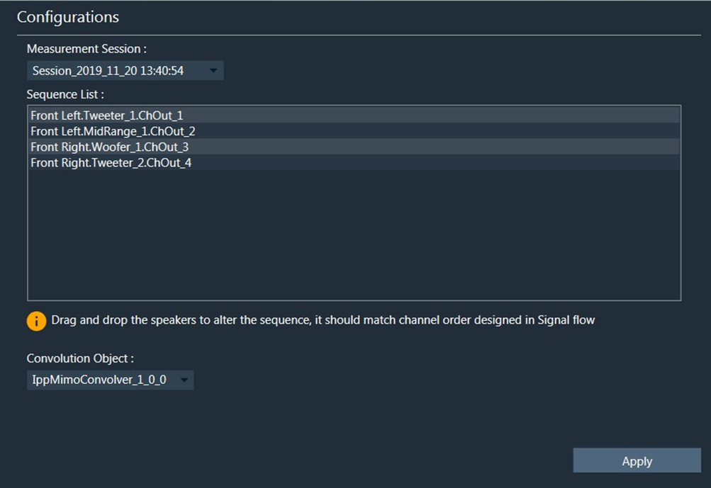
  1. Select a device, and click Virtual Tuning. This opens the Virtual tuning configuration screen.
    Graphical user interface, text Description automatically generated

Apply Coefficients to Virtual Tuning

Steps to apply coefficients to Virtual Tuning:

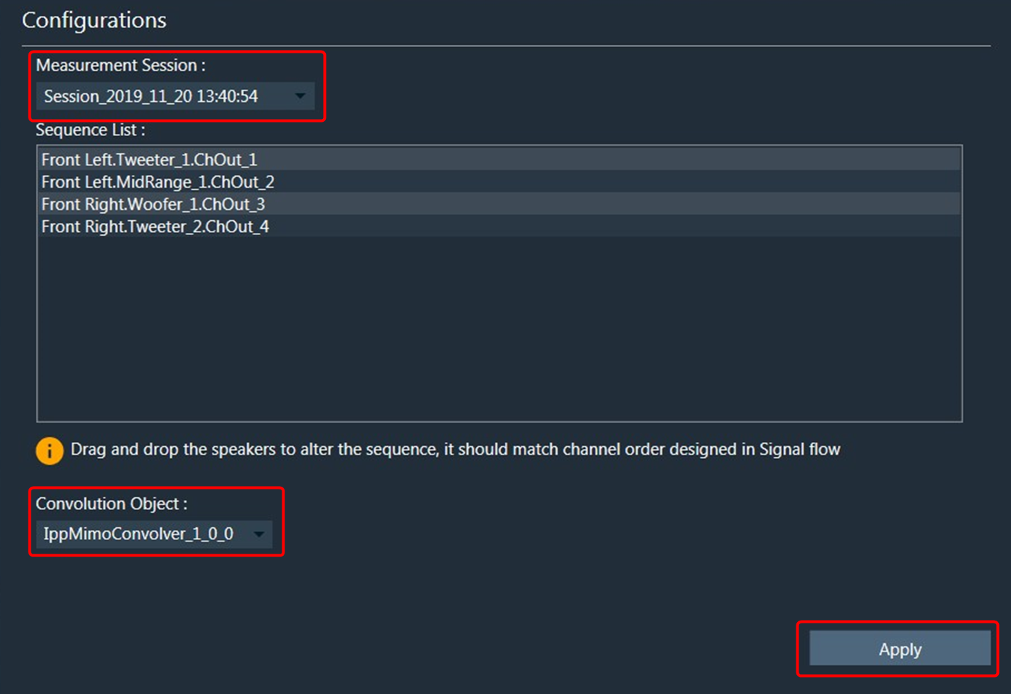
  1. Open Virtual Tuning and select suitable Measurement Session.
  2. Select Convolution Object to which the Coefficients to be applied.
  3. Click Apply.

The selected measurement’s IRData is retrieved and applied to the convolver object. A toast message appears, stating that the coefficients were successfully applied.
Graphical user interface, text, application Description automatically generated

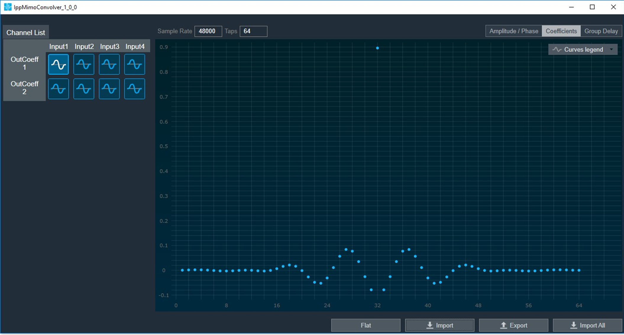
Virtual Tuning Panel: The IppMimoConvolver panel is used to view the coefficients assigned to the object. This panel provides the following functions.

  • Flat
  • Import
  • Export
  • Import All

About Global Tuning Tool

The Global Tuning Tool (GTT) is a software tool developed by Harman International, a leading audio and electronics company. The tool is designed to help audio engineers to create audio post-processing pipelines and tune audio the systems to get the best audio performance.

This is a windows-based tool that is part of the Harman AudioworX product suite. The Global Tuning Tool includes a comprehensive set of core audio functions, a powerful signal flow designer, tuning tool, and the framework for processing the entire audio signal path, enabling easy integration of both HARMAN and 3rd party technologies.

Key Features of Global Tuning Tool

  • Real-Time Analysis: The software provides real-time analysis of audio system performance, allowing engineers to quickly tune the system as per requirement.
  • System Optimization: The Global Tuning Tool uses advanced algorithms to optimize the audio system performance, based on the specific acoustics of the venue and the desired sound quality.
  • Intuitive User Interface: The Global Tuning Tool features an intuitive user interface, with easy-to-use tools and visualizations, making it easier for engineers to make adjustments and optimize the sound system performance.
  • Preset Management: The software includes a library of preset configurations for different types of venues and events, making it easier for engineers to get started and save time during the tuning process.
  • Signal Flow Designer: The software allows users to drag and drop audio processing modules such as volume, limiter, filters, and mixers onto a virtual canvas, and then connect the input/output pins of modules to create a signal flow diagram. The signal flow diagram provides a visual representation of the path that an audio signal takes through a system, including where it is processed, amplified, and mixed with other signals.

Relative Topics

Routing (Connections)

Routing in device view is supported at different levels

  • Device Routing.
  • Core Routing.

Device Routing

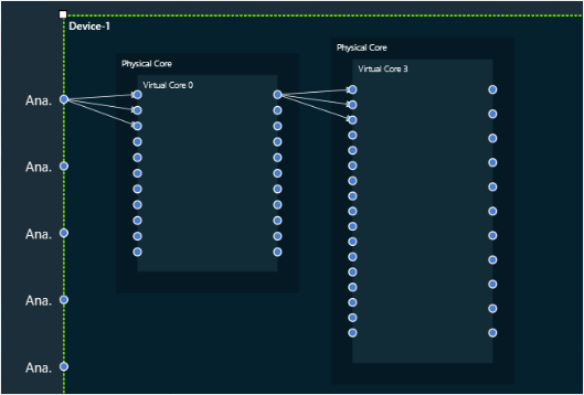
  • User can connect starting from input of the Device to any virtual core inside it.
  • Routing is also possible between the virtual cores. i.e., A virtual core output could be connected to the input of another virtual core.
  • 1:N routing is supported at this level. i.e., A device input can connect to multiple Virtual Cores. And a virtual Core Output could be connected to multiple virtual core inputs.
  • Not all the device inputs can connect to all Virtual Cores and similarly not all Virtual Cores can be connected to each other. There are few validations put in place. Please find the below list of validations for device routing.

Validations

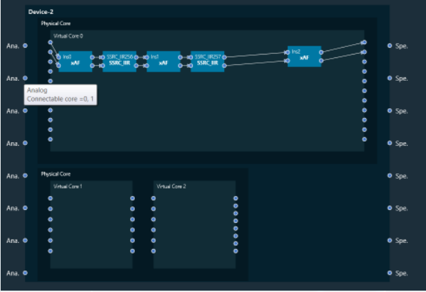
    • Based on the information available on the Device, the connectable cores for a Device input is displayed when ever the user hovers on the input connection pin. Also the connection pin name is displayed on hovering the mouse. The below image indicates the Device input pin 2 can be connected to Virtual Core 0 or Virtual Core 1.
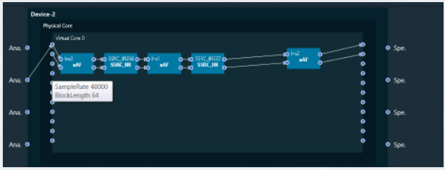
    • Each Virtual Core is associated with some Sample Rate and Block Length. This information could be seen when hovered over the Virtual Core Pin.
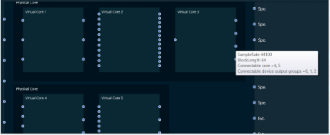
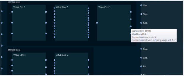
    • Based on the information available on the Device, the Connectable cores and Connectable device output groups for a Virtual core output is displayed when ever the user hovers on the output connection pin. The below image indicates the Virtual core 3 output  pin 3 can be connected to Virtual Core 4 or 5 or Device output group 0, 1 or 2. Virtual Core Outputs can connect to other virtual core inputs even if the sample rate and block lengths do not match.
    • Device output group can be known by hovering on the device output pin. In the below image the pin Speaker belongs to Group 0.

Core Routing

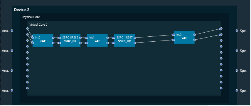
  • User can connect starting from input of the virtual core to core objects inside it and then to the output of the virtual core.
  • Connecting the virtual core input to its output is not allowed. A core object has to be put in between virtual core input and output pins.
  • For connecting between the instances, both the connecting core objects should have same block length and sample rate.
  • If there is a need to connect two instances with different Block Length/Sample Rate, then user may use a Buffer/SSRC_IIR objects to get the desired output.

Device identification feature will only be enabled for audio libraries versions 13 and greater.