Source objects category contains following audio objects.
Noise Generator Panel
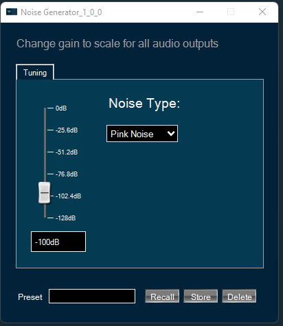
The Noise Generator Panel is used to change noise type and noise level. In SFD you can configure several output channels. The same noise type and level will be applied to each channel.
Noise Generator panel works only with PRO object modes “Pro-Prbs” and “Pro-Lcg”. Panel will not work in “WhiteNoise” and “PinkNoise” object modes.
Changing Noise Level
You can change the noise level by three ways:
- Using slider button: Select the slider to adjust the value.
- Using mouse scroll: Use mouse scroll to adjust the value.
- Enter an exact value in the text box.
Changes will take place after hitting the “Enter” key or by moving the focus away from the text box.
Changing Noise Type
You can change the noise type by clicking on the combo-box and selecting the type.
Possible noise generator types are:
- White Noise
- Pink Noise
Delay Panel
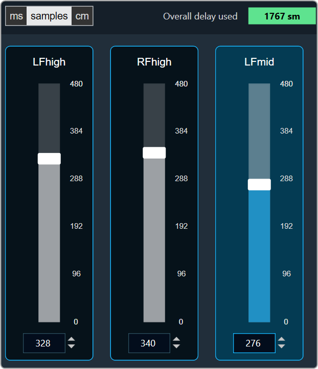
The Delay panel associated with Delay audio object. The Delay panel is used for changing the delay of the signal for each channel.
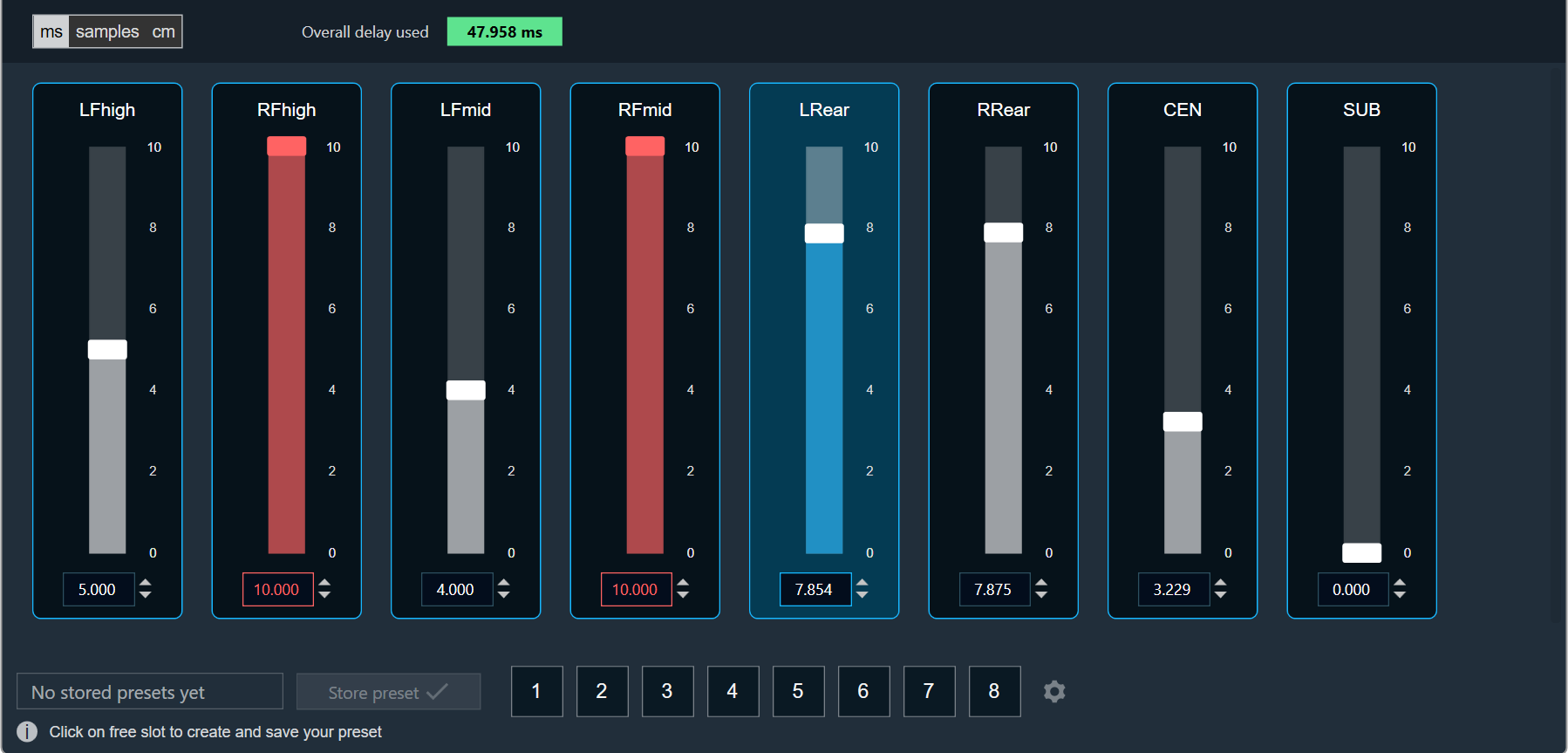
- Maximum / Minimum Delay Value: The maximum and minimum delay values are from corresponding state variable of Delay.
- Threshold Values: The maximum and minimum threshold values are derived from the GTT in the ParameterStore. Once the threshold value is reached, the Delay value bar will change to red color.
- Maximum threshold value: 95 %
- Minimum threshold value: Not set
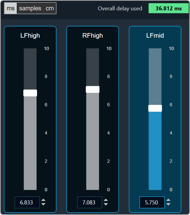
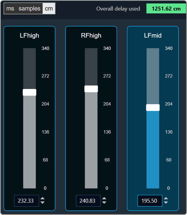
- Changing Units: You can switch between the milliseconds, samples, centimeters.
| Milliseconds
|
Samples
|
Centimeters
|
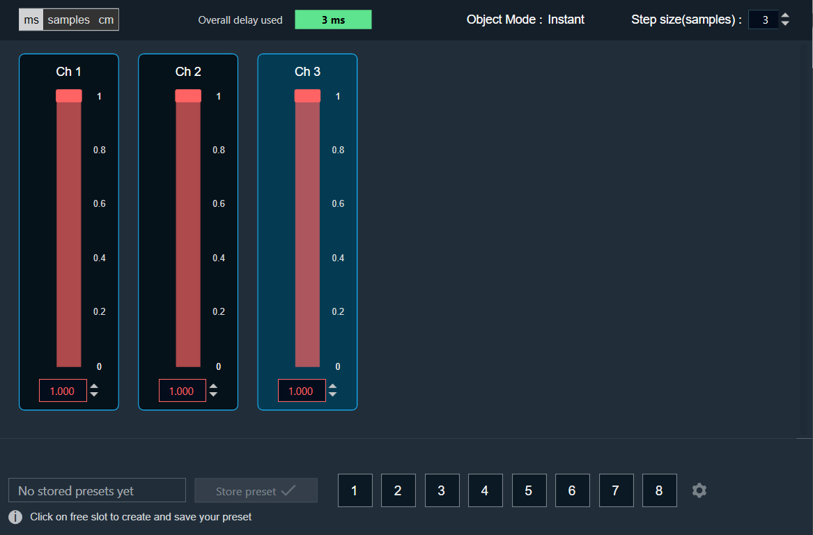
- Object Mode (Instant/CrossFade): In GTT the delay values are derived from the parameter store. Each channel’s delay value is configurable from 0 to Max Delay.
- Object Mode (DelayPool): In GTT the delay values are derived from the parameter store. When the object mode is set to DelayPool, the “Overall delay used” shown is sum of delay values of all the channels. Sum of the delay of channels is expected not to exceed Max Delay. Changes in delay values are accepted by the audio object only when sum does not exceed Max Delay.
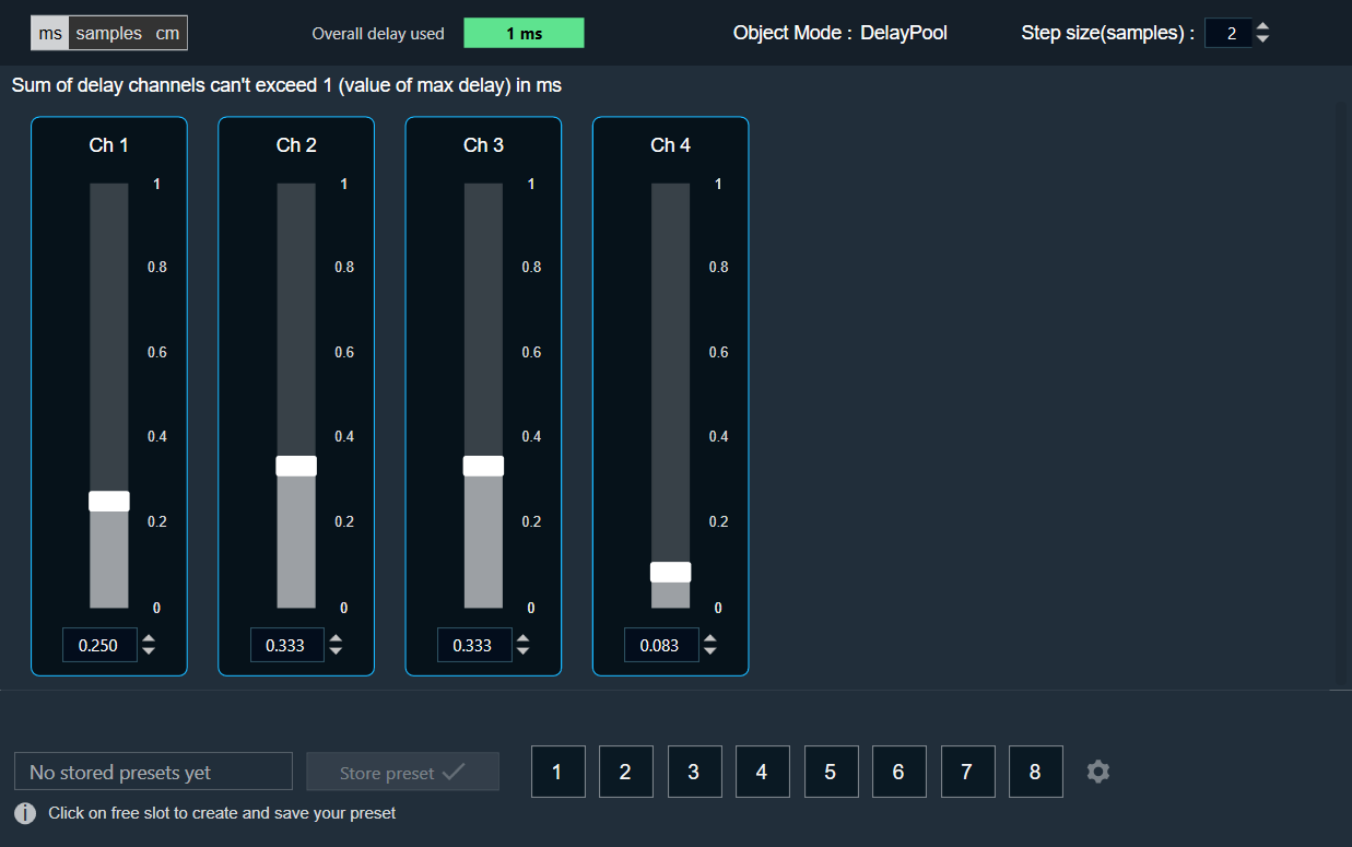
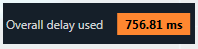
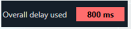
You can find the overall “delay value used” at the top of the Delay panel. The value in text area changes its color depending on the percentage of the maximum overall delay value.
-
- Up to 80 % of the delay pool
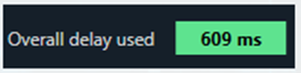
- From 80 % – 100 % of the delay pool
- 100 % of the delay pool
- Up to 80 % of the delay pool
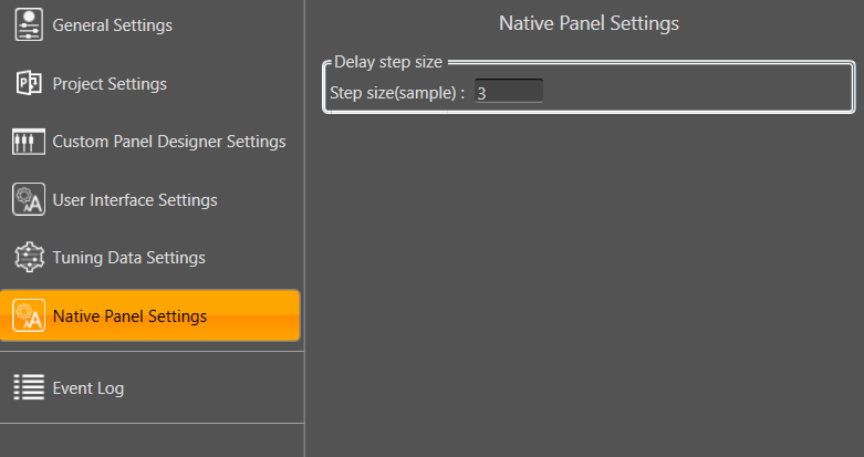
- Step Size for delay: In the application settings, you can change the global step size. The local step size in the delay audio object is derived from the global step size specified in the application settings. When you change the value of the local step size, the global step size value is no longer used.
To change the Delay Value
You can change the delay value in four ways:
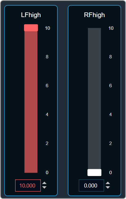
- Using slider button: Select the slider to adjust the delay value.
- Using mouse scroll: Hover on the respective column and use mouse scroll to adjust the delay value.
- Using text box: Select the respective column and enter the dB value within the specified minimum and maximum range. Once you’ve entered the value, press Enter, and the slider will automatically adjust based on the input.
- Using the increase and decrease buttons
 the delay calculated step value (based on max delay (ms)).
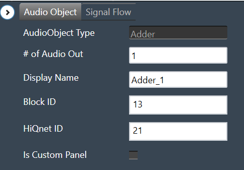
Adder
The Adder audio object sums the samples of 2 audio channel input buffers and writes their sum to the output buffer. Thus, the number of input channels is always twice the number of output channels:
This module sums the pairwise contents of m_NumAudioIn audio buffer channels and writes the result to the output buffer. For this audio module, m_NumAudioIn is always double m_NumAudioOut.
Use Case: This object can be deployed whenever the sum of two audio channels or pairs of audio channels is required in the audio pipeline.
Adder Properties
Below table describes about the Adder audio object properties and functionality.
| Properties | Description |
| # of Audio Out | Adder audio object has a number of input channels that is double the number of output audio channels.
The number of output channels is configurable in SFD, and the number of input channels is derived accordingly. |
| Display Name | Display the name of the Adder audio object in signal flow design. It can be changed based on the intended usage of the object. |
Mode
There are no mode available for Adder audio object.
Additional Parameters
There are no additional parameters available for Adder audio object.
Tuning Parameters
There are no tuning parameters available for Adder audio object.
Control Interface
There are no control parameters available for Adder audio object.
Native Panel
Adder audio object does not support native panel.
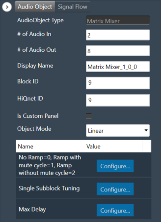
Matrix Mixer
The Matrix Mixer audio object is used to calculate weighted output audio based on a combination of input audio. In addition to this, the object also supports delay of input channels.
Use Case: The Matrix Mixer takes in a configurable number of input and output channels. Each output of this object is a weighted sum of all the input channels. Any input can get summed into any output with or without a delay.
Matrix Mixer Properties
Below table describes about the Matrix Mixer audio object properties and functionality.
| Properties | Description |
| # of Audio In | Number of input channels.
|
| # of Audio Out | Number of output channels.
|
| Display Name | Display the name of the Matrix Mixer audio object in signal flow design. It can be changed based on the intended usage of the object. |
| Object Mode | Matrix Mixer object operates in one of the following two modes.
|
This object supports DelayMatrixMixer function.
Mode
The Matrix Mixer object supports two different modes of operation.
| Mode | Description |
| Linear (Default) | In this mode, the gain values (channel weights) are configurable on a linear scale in the range -10 to +10. |
| dB | In this mode, the gain values are configurable in decibels in the range between -128 dB to 20 dB and these decibel values are converted to linear values by xAF by the formula given below before multiplying with input channel samples.
|
Additional Parameters
The Matrix Mixer audio object can be configured with the following additional parameter:
| Parameter | Descriptions | |
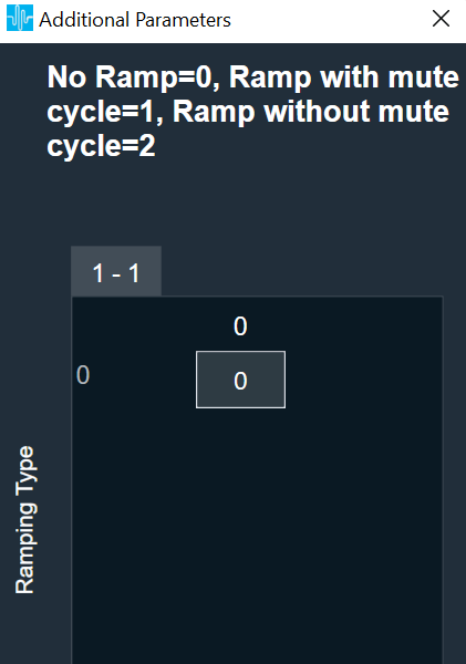
| No Ramp = 0,
Ramp with mute cycle = 1, Ramp without mute cycle = 2 |
The mixer also has three ramping types that can be configured through an additional number of parameters:
In the SFD, you can set the number of input and output channels. These channels do not need to be identical. The mode and ramping type are also configurable in the SFD. In the GTT, the Matrix Mixer exposes variables for tuning, for each input and output channel. You can modify these to change the weights used to scale the input channels. In the ramp modes, additional ramp time and control variables are exposed as explained above |
 |
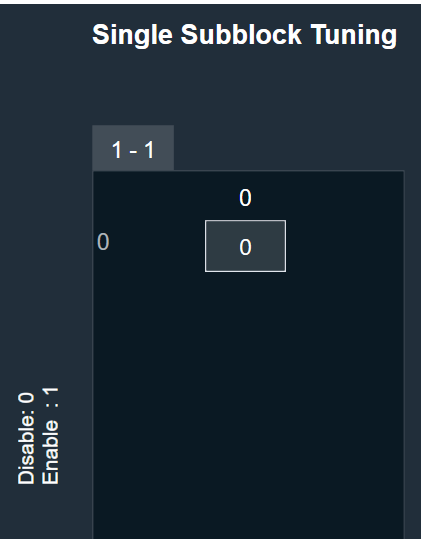
| Single Subblock Tuning | The object has an additional configuration variable “Single Subblock Tuning” to enable or disable it. On enabling it, allows contiguous memory allocation and the gain values can be tuned as single subblock.
By Default, Single Subblock Tuning is disabled. |
 |
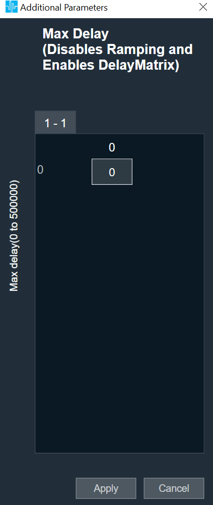
| Max Delay | The object has an additional configuration variable “Max Delay”.
Range: The value ranges from 0 to 500000 samples. By default, it is set to 0 samples. Ramp with mute cycle and Ramp without mute cycle types are not supported when Max delay is greater than 0. There is no native panel for DelayMatrixMixer |
 |
Tuning Parameters
The GTT can read or write into parameter memory using tuning command respectively. The memory stores a value per output channel that has a gain value to be multiplied by per input channel based on the mode. These parameters are tunable. Assuming the object is composed of NIn input channel and Nout output channels, the description will look as follows (depending on gain type).
For No Ramp mode
Parameter memory for “No Ramp” mode with Linear Gain
| Linear Gain | ||||||||
| Sub-block ID (Single Subblock tuning: Disabled) |
Sub-block ID (Single Subblock tuning: Enabled) |
Name | Type | Unit | Min | Max | Default | Description |
| 0 | 0 | float | -10 | 10 | 0 | NIn gain inputs for Ch0 output | ||
| 1 | 0 | NIn gain inputs for Ch1 output | ||||||
| … | 0 | … | ||||||
| Nout-1 | 0 | NIn gain inputs for ChNout-1 output | ||||||
Parameter memory for “No Ramp” mode with Logarithmic Gain
| Logarithmic Gain | ||||||||
| Sub-block ID (Single Subblock tuning: Disabled) |
Sub-block ID (Single Subblock tuning: Enabled) |
Name | Type | Unit | Min | Max | Default | Description |
| 0 | 0 | float | dB | -128 dB | 20 dB | -128 dB | NIn gain inputs for Ch0 output | |
| 1 | 0 | NIn gain inputs for Ch1 output | ||||||
| … | 0 | … | ||||||
| Nout-1 | 0 | NIn gain inputs for ChNout-1 output | ||||||
For Ramp with mute cycle mode
It has an additional ramp time configurable parameter.
Parameter memory for “Ramp with mute cycle” mode ramping with Linear Gain
| Linear Gain | ||||||||
| Sub-block ID (Single Subblock tuning: Disabled) |
Sub-block ID (Single Subblock tuning: Enabled) |
Name | Type | Unit | Min | Max | Default | Description |
| 0 | 0 | float | -10 | 10 | 0 | NIn gain inputs for Ch0 output | ||
| 1 | 0 | NIn gain inputs for Ch1 output | ||||||
| … | 0 | … | ||||||
| Nout-1 | 0 | NIn gain inputs for ChNout-1 output | ||||||
| Nout | 1 | Ramp Time | float | ms | 0 | 5000 | 500 | The time it takes for the ramp to complete. This value is split in half between muting and unmuting stages of the output signal. |
Parameter memory for “Ramp with mute cycle” mode ramping with Logarithmic Gain
| Logarithmic Gain | ||||||||
| Sub-block ID (Single Subblock tuning: Disabled) |
Sub-block ID (Single Subblock tuning: Enabled) |
Name | Type | Unit | Min | Max. | Default | Description |
| 0 | 0 | float | dB | -128 dB | 20 dB | -128 dB | NIn gain inputs for Ch0 output | |
| 1 | 0 | NIn gain inputs for Ch1 output | ||||||
| … | 0 | … | ||||||
| Nout-1 | 0 | NIn gain inputs for ChNout-1 output | ||||||
| Nout | 1 | Ramp Time | float | ms | 0 | 5000 | 500 | The time it takes for the ramp to complete. This value is split in half between muting and unmuting stages of the output signal. |
For “Rampwithout mute cycle” mode
It has an additional ramp characteristics parameters which are ramp down time, ramp up time, ramp down shape and ramp up shape.
Parameter memory for “Ramp without mute cycle” mode ramping with Linear Gain
| Linear Gain | ||||||||
| Sub-block ID (Single Subblock tuning: Disabled) |
Sub-block ID (Single Subblock tuning: Enabled) |
Name | Type | Unit | Min | Max | Default | Description |
| 0 | 0 | float | -10 | 10 | 0 | NIn gain inputs for Ch0 output | ||
| 1 | 0 | NIn gain inputs for Ch1 output | ||||||
| … | 0 | … | ||||||
| Nout-1 | 0 | NIn gain inputs for ChNout-1 output | ||||||
| Nout | 1 | Ramp down Time | float | ms | 0 | 5000 | 500 | The time it takes for the ramp to complete. |
| Nout | 1 | Ramp up time | float | ms | 0 | 5000 | 500 | The time it takes for the ramp to complete. |
| Nout | 1 | Ramp down shape | Int | 0 | 2 | 1 | Ramping shape, it can be jump (0), linear (1) and exponential (2). | |
| Nout | 1 | Ramp up shape | int | 0 | 2 | 1 | Ramping shape, it can be jump (0), linear (1) and exponential (2). | |
Parameter memory for “Ramp without mute cycle” mode ramping with Logarithmic Gain
| Logarithmic Gain | ||||||||
| Sub-block ID
(Single Subblock tuning: Disabled) |
Sub-block ID
(Single Subblock tuning: Enabled) |
Name | Type | Unit | Min | Max | Default | Description |
| 0 | 0 | float | dB | -128 dB | 20 dB | -128 dB | NIn gain inputs for Ch0 output | |
| 1 | 0 | NIn gain inputs for Ch1 output | ||||||
| … | 0 | … | ||||||
| Nout-1 | 0 | NIn gain inputs for ChNout-1 output | ||||||
| Nout | 1 | Ramp down time | float | ms | 0 | 5000 | 500 | The time it takes for the ramp to complete |
| Nout | 1 | Ramp up time | float | ms | 0 | 5000 | 500 | The time it takes for the ramp to complete |
| Nout | 1 | Ramp down shape | int | 0 | 2 | 1 | Ramping shape, it can be jump (0), linear (1) and exponential (2). | |
| Nout | 1 | Ramp up shape | int | 0 | 2 | 1 | Ramping shape, it can be jump (0), linear (1) and exponential (2). | |
DelayMatrixMixer
The object functions as DelayMatrixMixer with Delay Pool when the additional configuration variable “Max Delay “ is set to more than 0 samples. A “Delay” tuning parameter is added in addition to the gain parameter for each input channel. The delay buffer (of length Max Delay) is shared by all the channels. Therefore, the available delay for each channel depends on the delay values configured for the other channels. The input channels are multiplied with the channel weights and are applied with delay configured and summed at the output channel.
| Parameter | Description | Range | Default |
| Delay | Delay to be applied across each channel. | 0 to Max Delay(samples) | 0 |
| Gain | Gain to be applied across each channel | Linear: -10 to +10
dB: -128 dB to 20 dB |
Linear: 0
dB: -128 dB |
Control Interface
There are no control parameters available for Matrix Mixer audio object.
Merger
The Merger audio object applies linear gain to all channels and sums all channel samples to generate an additional output channel. In the GTT, this object exposes m_NumAudioIn variables that represent the weights by which the input channels are scaled to generate the output for the last output channel. Scale values are to be set in db.
Use Case: This object can be deployed whenever a combination of input channels is required in the audio pipeline.
Merger Properties
Below table describes about the Merger audio object properties and functionality.

| Properties | Description |
| # of Audio In | Number of output channels is always one greater than the number of input channels. The first m_NumAudioIn output channels are just copies of the input channels.
Number of output channels is always number of input channels plus one. The first m_NumAudioIn output channels are just copies of the input channels. Default number of inputs pins is 2 and output pins is 3. |
| Display Name | Display the name of the Merger audio object in signal flow design. It can be changed based on the intended usage of the object. |
Mode
There are no mode available for Merger audio object.
Additional Parameters
There are no additional parameters available for Merger audio object.
Tuning Parameters
Below table describes the tuning parameters of Merger audio object.
| Parameter | Description | Data Type | Unit | Default | Range |
| Gain | Each input channel has one gain tuning parameter that specifies the weighting factor to be used to generate the additional output. | float | dB | -128 | -128 to 20 |
Control Interface
There are no control parameters available for Merger audio object.
Native Panel
Merger audio object does not support native panel.
Router
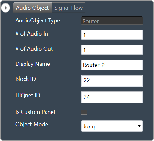
The Router audio object routes any of the input channel to any output channel without changing samples of the source. Additionally, you can route the same input channel to multiple output channels.
In the SFD, you can select the values that they prefer for “# Input channels” and “# Output channels”. These values can be distinct.
Use Case: This object can be deployed whenever each output channel is routed to any one of the input channels.
Router Properties
Below table describes about the Router audio object properties and functionality.
| Properties | Description |
| # of Audio In | Enter the number of input channels.
|
| # of Audio Out | Enter the number of output channels.
|
| Display Name | Display the name of the Router audio object in signal flow design. It can be changed based on the intended usage of the object. |
| Object Mode | Router object operates in one of the following two modes.
|
Mode
Router object supports two different modes of operation. After selecting the router object in GTT, one can configure the modes as described below.
By default, the router object is configured to operate in the Jump mode.
- Jump: In this mode, the object performs the tuning or routing without any ramping and switches the input to output routing between two calc calls. This might cause clicks and pops if no fading or mute stage is performed on an instance or core level.
- Ramping: In this mode, the object will perform a ramping while changing the input to output routing. In addition to the routing parameters this mode supports a tuning of the ramp time in the range of 0 to 5 seconds.
Presently, the object supports only linear ramping. The ramping type is not configurable.
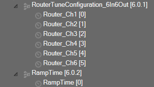
If the router is configured with six input and six output channels, the tuning parameters will be displayed in GTT as shown below.
Additional Parameters
There are no additional parameters available for Router audio object.
Tuning Parameters
Below table describes the tuning parameters of Router audio object.
| Parameter | Description | Unit | Data Type | Default | Range |
| Router | Each output channel has this parameter to configure the Input channel number to route to the particular output channel.
This parameter is available in both modes. |
None | ULong | 1 | 1 to Number of Audio Inputs |
| RampTime | Ramping time
This parameter is available only in Ramping mode |
Seconds | Float | 0.5 | 0 to 5 |
Control Interface
There are no control parameters available for Router audio object.
Splitter
The Splitter audio object copies the samples of one input channel to multiple output channels.
Use Case: This object can be deployed whenever an input channel to an object is required to be replicated to multiple channels at the output.
Splitter Properties
Below table describes about the Splitter audio object properties and functionality.
| Properties | Description |
| # of Audio Out
# of Audio In |
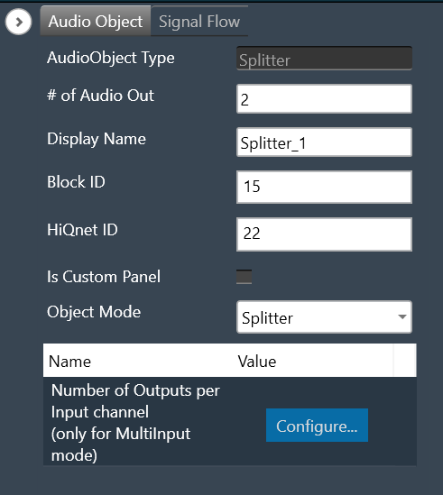
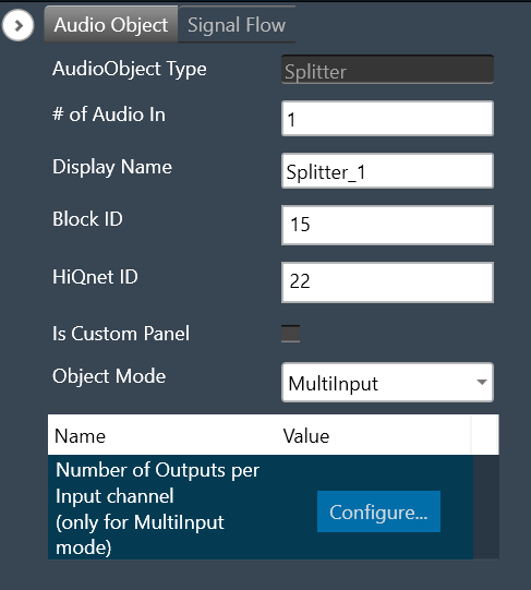
In Splitter, the number of input and output channels depends on the selection of object mode.
– # of Audio Out: When the object mode set as “Splitter”, you can configure number of the output channel in the “# of Audio Out” field.
# of Audio Out is the default configuration. – # of Audio In: When the object mode set as “MultiInput”, you can configure number of the input channel in the “# of Audio In” field as per below range.
|
| Display Name | Display the name of the Splitter audio object in signal flow design. It can be changed based on the intended usage of the object. |
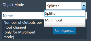
| Object Mode | The audio object channel can be configured in one of the two operation modes.
|
Mode
Splitter object operates in one of the two modes.
- Splitter
- MultiInput
| Mode | Description |
| Splitter | The purpose of Splitter mode is to copy the input audio data N times to the output buffers. In this mode you can set the number of output channels and number of input channel is always fixed to one. The object replicates the single input channel to all output channels of the object. This is the default mode. The additional parameter “Number of Outputs per Input channel” is not supported in Splitter mode. |
| MultiInput | The purpose of the MultiInput mode is to use one instance of the audio object instead of instantiating it N times if you have N channels. The number of output channels equals the number of audio inputs multiplied by the value entered in the additional configuration variable “Number of Outputs per Input channel”. The maximum number of audio outputs is determined by the number of inputs, as number of output channel per object cannot exceed 255. It splits multiple signals the same number of times. The number of copies of each input channel produced at the output is determined by the value set in the additional configuration variable. 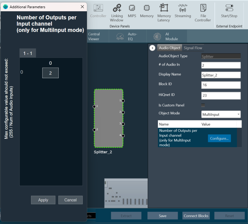 In this mode, the splitter takes in input 1 and sends it to output 1 and 2. Input 2 is sent to output 3 and 4. 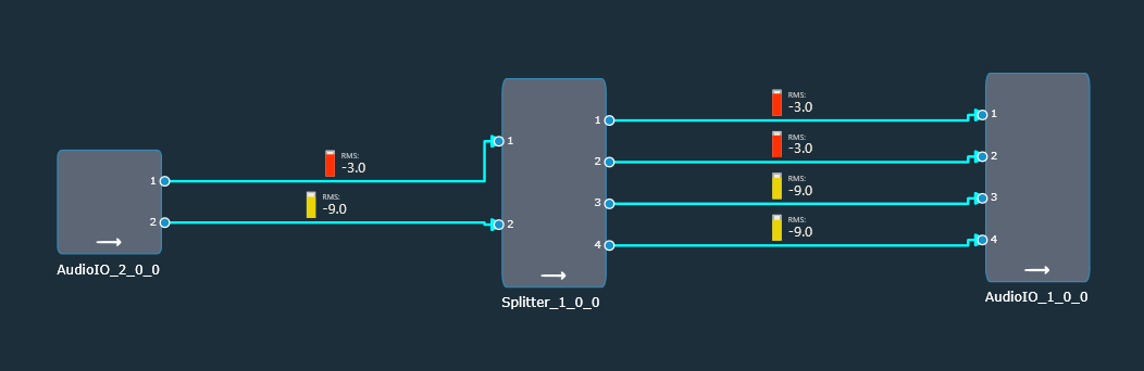 |
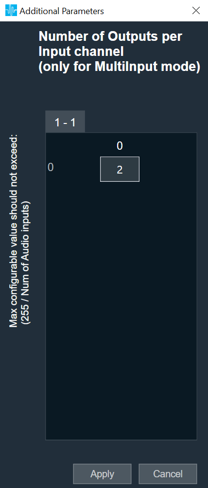
Additional Parameters
| Parameters | Description | |
| Number of Outputs per Input channel | The object has an additional configuration variable “Number of Outputs per Input channel” for MultiInput mode. It denotes the number of copies of each input channel. It is configurable between 2 to (255/Number of Audio Inputs). ForFor example, if number of audio inputs are set to 25. Then the “Number of Outputs per Input channel” value is configurable between 2 to 10 as the maximum number of output channels supported cannot exceed 255. Default: 2 |
 |
Tuning Parameters
There are no tuning parameters available for the Splitter audio object.
Control Interface
There are no control parameters available for the Splitter audio object.
Native Panel
Splitter audio object does not support a native panel.
Demux
The Demux audio object routes input channel samples to any one of the output channels without any change in sample values whereas the rest of the output channels have zero values.
This audio object has a single input audio buffer and several output buffers. The number of output channels is configurable in the SFD.
The Demux object always has one variable that the GTT can access, and that variable is the one that determines which output channel the input should be written.
Use Case: This object can be deployed whenever an input channel to an object is required to be routed to one specific output channel (selected via tuning).
Demux Properties
Below table describes about the Demux audio object properties and functionality.

| Properties | Description |
| # of Audio Out | Enter the number of output channels. Based on a tuning variable, it selects the output where the input should be sent. Only one of the Demux audio objects output channels will have data at any one time.
The Demux object always has 1 input channel. |
| Display Name | Display the name of the Demux audio object in signal flow design. It can be changed based on the intended usage of the object. |
Mode
There are no mode available for Demux audio object.
Additional Parameters
There are no additional parameters available for Demux audio object.
Tuning Parameters
Below table describes the tuning parameters of Demux audio object.
| Parameter | Description | Data Type | Unit | Default | Range |
| Demux_Ch | Output channel index to route the input to (starting from channel index 1) | Unsigned Long | None | 1 | 1 to Number of output channels |
Control Interface
There are no control parameters available for Demux audio object.
Native Panel
Demux audio object does not support native panel.