Change Audio Object Processing State

Audio engineers require a method for conducting A/B testing of signal flows and load balancing, as well as a simpler way to troubleshoot tuning data if errors occur.
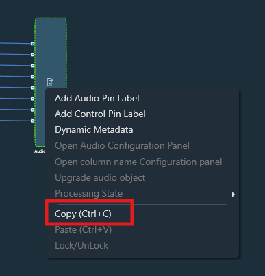
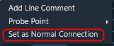
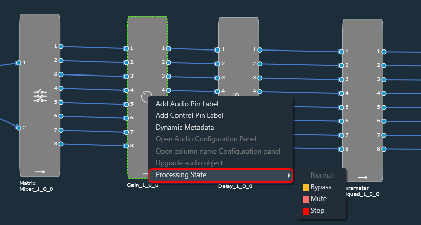
You can achieve this by using the “Processing State” functionality, where you can change the audio object processing state.

The processing State function is only available when the device is connected.

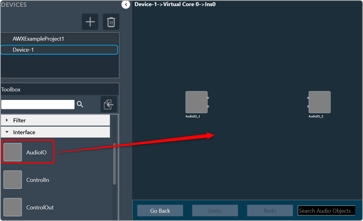
These options are available to all audio objects except interface objects like Audio-In, Audio-Out, Control-In, and Control-Out. For the compound audio object, the selected state will be applied to all inner audio objects.

Following are the tasks carried out on the xAF side for each state:

  • Normal: Normal operation with the update of necessary internal states of the audio object; normal output.
  • Bypass: Normal operation with the update of necessary internal states of the audio object; input channel buffer data copied to the output channel buffers.
  • Mute: Normal operation with the update of necessary internal states of the audio object; output channel buffers cleared.
  • Stop: Input channel buffer data copied to the output channel buffers (no update of internal states).

The above states are only available through GTT for regular audio objects, and only Normal and Mute states are available for source objects such as Waveform generators.

Audio object which has a state other than ‘Normal’ cannot be tuned through the Native Panel.

Ramping


Linear ramping is provided with a ramp-up or ramp-down time of 50 ms. to ensure a smooth transition between states.
Ramping is not provided for any transitions involving the Bypass state, and each audio object must support it.
For the transition between Normal and Stop states, first the output is ramped down from the present state to the Mute state and then ramped up to the target state.
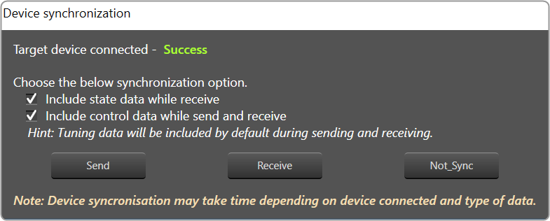
Every time you connect GTT to the device, audio object states from the device are read and applied to the signal flow designer. If you reboot the device, the processing states of Audio Objects will be set to ‘Normal’.

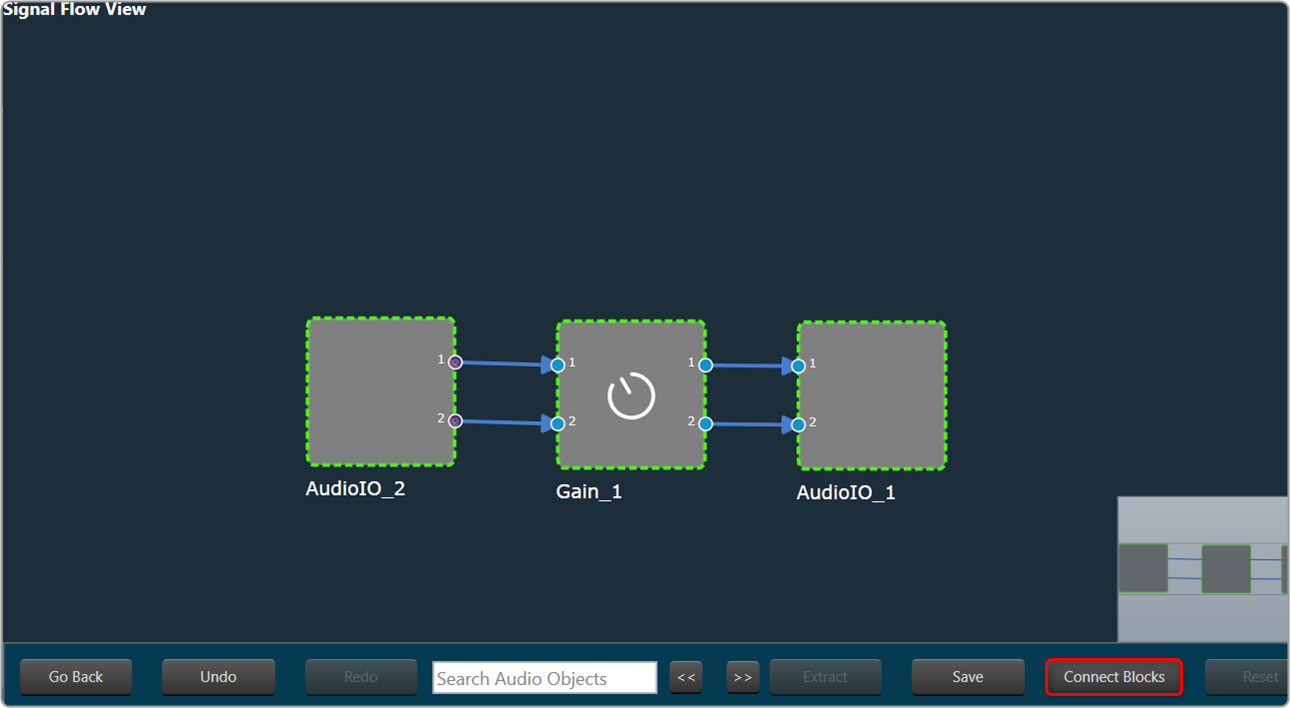
In signal flow designer you can reset all audio objects processing state to ‘Normal’ by using the ‘Reset’ button.

Copy and Paste Operation

The signal flow designer offers the capability to copy and paste audio objects, which can accelerate the design process. You can select a complete signal flow or a part of the signal flow. All the audio object properties will be copied along with UI properties.
Additionally, you can copy and paste the compound audio object.

Use the CTRL+C shortcut to copy selected audio objects and CTRL+A  & CTRL+C to copy the entire signal flow design.

To copy the single audio object follow the below steps:

  1. In the signal flow designer, right-click on an object and select Copy from the context menu or use CTRL+C to copy.

    After the object or signal flow design is copied, you can paste it into the same or a different framework instance.
  2. Right-click on the signal flow designer and select Paste from the context menu or use CTRL+V to paste the audio object.

To copy the multiple audio objects follow the below steps:

  1. In the signal flow designer, hold the Ctrl key and click on each object you want to copy or use CTRL+A to select all objects in the designer.
  2. Right-click on the selected objects and choose Copy selected items from the context menu or use the keyboard shortcut Ctrl+C.
  3. Right-click on the desired location in the signal flow designer where you want to paste the copied objects, select Paste from the context menu or use the keyboard shortcut Ctrl+V.

Copy and paste operations can also be performed outside the audio object selection.

Undo and Redo Operation

The undo and redo feature allows you to reverse or redo previous actions.

  • Undo: The undo feature allows you to reverse the previous action by restoring the design state to a previous design state.
  • Redo: The redo feature allows you to perform the action that is undone.

Undo and redo feature is not available in the tuning flow view.

Undo/Redo operation is supported for the following actions:

  • Add/Remove of audio objects.
  • Add/Remove of audio object connections Audio object movements.
  • Audio object property changes.
  • Additional parameter, additional parameter config changes Pin label, connection label changes.
  • Copy/Paste of audio objects.
  • Audio object processing state actions.
  • Extract CAO.

The scope of Undo/redo will be within the specific instance.

In some cases, a toast message appears to help invisible items getting undone or re-done.

  • Additional parameter config panel changes.
  • When processing state cannot be applied.

Undo/redo action will not restore the tuning data.

This feature is limited to 1000 actions.

When a new manual action is perfromed, all existing redo records will be cleared. As a result, it will not be possible to redo any previous actions.

Block Control

This feature enables signal flow designer to group multiple control signals into a block control.

Audio objects needed or block control signal to control signal conversion and vice-versa.

  • Control Grouper: Facilitates SFD user to group the control signals into block control.
  • Control Splitter: Facilitate SFD user to split the individual control signals.

Any audio object which supports block control should declare a flag in dynamic metadata as below.

The block control connections are highlighted as thick lines in both SFD and CAO signal flows.

Block control pins are in dark orange color and on connection mouse hover block pin details are displayed.

It is possible to make block connections only when the group count matches. Else a validation error will be thrown.

If the group count is 1, it is possible to connect normal control pin with block control pin.

Signal Flow Design Validation

DDF Template Validation

In case there are issues with the DDF file generated by the toolbox during creating a device or modifying of the signal flow, an error notification will be displayed. GTT will recognize any audio object that is incomplete or has failed as corrupt.

It is recommended that you should fix the DDF template of the affected audio object and proceed with your work.

  • If you import or open a project that contains a corrupted audio object, a warning message will be displayed.

    On opening the signal flow which has corrupted object, the corrupted audio object will be highlighted as shown below, and the same will be displayed in the compiler error window.
  • If the signal flow has corrupted objects on sending or exporting signal flow, the following message will be displayed.
    A screenshot of a computer Description automatically generated with medium confidence
  • If there is a mismatch between Sample Rate/ Block Length of instance signal flow and current audio object in the toolbox, then a warning message pops up and the corresponding object will be disabled in the toolbox.
  • If there is a version mismatch between the current audio library version and the version data on the device, a warning message appears asking whether to continue or stop saving.
  • If there is a tuning version mismatch between audio objects in the signal flow and audio objects in the toolbox, a warning message will be displayed, showing the tuning version differences, and those audio objects are highlighted in blue.
    A picture containing table Description automatically generated
  • If the Sample Rate/Block Length does not match, a message will be displayed asking if you want to continue or stop saving.

Additional Parameters Validation

The GTT will perform validation of input data in the additional parameters window, based on the information provided by the xAF dll for specific audio objects.

The below validations are added on xAF and GTT.

  • ASCENDING
  • DESCENDING
  • NOTEQUAL
  • EVEN
  • ODD
  • EVEN_ASCENDING
  • EVEN_DESCENDING
  • ODD_ASCENDING
  • ODD_DESCENDING

The below figure displays the value entered should be an odd value. An error message is displayed to when an even value is entered.

Feedback Loop in Signal Flow

In order to achieve complex reverb processing implementation, you can provide feedback of one audio object to another audio object, this can be achieved by adding feedback connections in signal flow. You can add one or more feedback connections in a signal flow.

On adding any audio connection, if loop detected in signal flow, following prompt will appear. On clicking “Yes”, the connection will be changed as feedback connection. On clicking “No”, the connection will be added as a normal connection.

An existing audio connection can be changed to feedback connection using context menu option “Set as Feedback Connection”.

An existing feedback connection can be changed to normal connection using context menu option “Set as Normal Connection”.

The keyboard shortcut “Ctrl+Alt+F” can be used to set a normal connection as feedback connection or vice versa. You can select one or more connections and use this keyboard shortcut.

The feedback connection will be shown as dashed yellow line as below,

You can mark any audio connection as feedback connection. But remember that, the feedback connections will be ignored/skipped during execution order calculation.

If any loop connection detected on save or if a legacy signal flow already has a loop connection, the designer will indicate this and an error with the compiler will be reported. In order to save the signal flow, you must first remove any existing loops or set the loop connections as feedback connections.

Feedback connections are supported inside CAO and on connections of CAO.

Self-loop is not allowed on an audio object.

The execution order of audio objects will not be changed on adding new feedback connections in a signal flow. But changing an existing connection to a feedback connection can affect execution order because the feedback connections will be ignored during execution order calculation.

InPlaceComputation will be disabled on audio objects with feedback loop connection. This includes audio objects which are source and target of feedback connection.

Separate stream indexes will be allocated for feedback connections. Same index will be allocated for input and output streams of feedback connection. These indexes when in use, will not be reused for other connection.

There is no restriction to add loops in control connections.

Support for Multiple Framework Instances

The xAF framework is designed to support a single core and a single instance running on that core as its default setting. However, it is possible to create a personalized xAFVirtualAmp version that supports multiple framework instances to be distributed over several cores.

Currently, the audio routing between cores at the device level and between instances at the core level is hardcoded. In the future, it will be possible to provide the routing configuration using GTT.

For now, the tool makes it possible to build signal flows consisting of multiple cores and framework instances, as well as to generate device descriptions for such setups. However, when creating a multi-core, multi-instance arrangement, it is necessary to have prior knowledge of the audio routing hardcoded in the xAFVirtualAmp library and adhere to its limitations.

Once the design is done, you can send a complete configuration (control configuration for a device and signal flow configurations for each framework instance) to a real or virtual device.

After completing the design, it is possible to send a complete configuration (including control configuration for a device and signal flow configurations for each framework instance) to a physical or virtual device.

To send configuration to a physical or virtual device:

  1. On the Device Designer view, click on Send Signal Flow.

Harman Audio Library Service

The Harman Audio Library Service (HAL) service is a wrapper around the xAFVirtualAmp library. It’s been created mainly because GTT is a 64-bit application, while xAFVirtualAmp is a 32-bit library, hence it is not possible to launch both binaries in the address space of the same process. In addition, GTT also supports 64-bit xAFVirtualAmp from “R Release”.

Internally, the HAL service is implemented as a WCF service hosted in a Windows service. It communicates with GTT via named pipes.

The Harman Audio Library Service exposes the following xAF API to GTT.

  • getAudioToolboxBuffer: Returns the AudioToolbox.xml file as a string. AudioToolbox.xml contains definitions of audio blocks known to a particular version of the xAFVirtualAmp library.
  • getIoObjectInformation: This method accepts audio block configuration parameters and returns the IO layout of the block (# audio ins, # audio outs, # control ins and # of control outs).
  • getTuningInformationBuffer: Returns a device description snippet for an audio block. Iterative invocation of that method for each audio block across all framework instances produces a device description file.

After a successful installation of GTT, the HAL service should be automatically initiated by default.

In case the service is not operational or has been deactivated for any reason, the GTT will notify you of such situations through error messages.

To activate the HAL services:

  1. Open GTT project window, click on Service Monitor. This opens service monitor window.
  2. On the Service Monitor window, click Refresh for Harman Audio Library.

Additional Audio Block Configuration Parameters

Audio Objects may require a different set of configuration properties than the default ones like # of channels, audio inputs, audio outputs, and number of elements. In such cases, it is possible to customize the configuration properties of the AO to better match the specific requirements of the device.

The LUT audio object serves as a suitable example; you need to define the number of rows and columns in the table. To facilitate this requirement, additional configuration parameters are added in both GTT and xAF.

Theoretically, an audio block can have any number of additional configuration parameters. These parameter definitions are obtained from the xAF library in conjunction with the parent block definition. The parameter definition consists of parameter order, name, and value, which are currently represented as floats. There are plans to enhance parameter definitions in the future to accommodate multiple parameter types.

When a metadata is available, the additional parameters are displayed as shown below.

On the Audio Object Property view, click on the Configure. The system will open an additional parameters window, where you can provide additional parameters. These additional parameters are of the same data type which is provided as part of parameters definition.

After making the necessary modifications, click the Apply and the system will implement the designated supplementary parameters.

Dynamic Additional Parameters

This feature is to change the size of additional parameters based on IO modifications. This feature is available for selected Audio objects which have “isAddVarUpdateRequired” flag set in their static metadata.

Create a Signal Flow

Before creating a signal flow, it is necessary to complete the following configurations.

  • Make sure you need to add a device to the project. For more information on how to create a project and add the device to the project, refer to Create a New Project.
  • Once you have created the signal flow, the next steps involve tuning and analyzing the signal flow. To analyze the signal flow according to your specific requirements, you need to configure the analyzer settings. The analysis can be performed using the IVP RTA window. For more details on IVP RTA settings, refer to Real Time Analyzer User Guide.

If you are running a virtual device, select WIN32(legacy) or WIN64 (IVP and VST3).

Not matching core types will cause issues on your device (virtual and real).

Signal Flow Design Recommendation
– There is no limit on the number of audio objects that can be added to a core. However, the optimal number of audio objects is 512. Beyond this number, GTT performance will be slightly impacted.
– GTT performs best when there is minimum 20% memory (RAM) available for the tool and CPU load is under 50% in terms of system resources.
– Maximum number of instances which can be added in a core is 255.

Follow the below steps to create a signal flow design:

    1. On the Device View, drag and drop the Xaf Instance from the toolbox to the virtual core

      This action opens the Configure I/O Channels message box.
    2. Enter the Input channel and Output channel value and click OK. The audio objects inside the signal flow designer are filtered based on the Data Format of the core.
    3. Select the Xaf Instance and configure the core object properties; Sample Rate and Block Length.
      • Sample Rate: This sample rate will be applied to all the audio blocks in the signal flow
      • Block Length: It is required internally by the xAF framework.
        Graphical user interface Description automatically generated
    4. Once you configured the Xaf Instance core object properties, click Save.
    5. Double-click on the Xaf Instance to open the Signal Flow Designer window.
    6. On the Signal Flow Designer, go to the Toolbox section, expand Interface, and drag AudioIO audio object to the design canvas. Similarly, add another AudioIO audio object to the design canvas.

       – When adding an xAF instance to a device that is already online, this AudioIO can be added. Thus, this step is only necessary if these two AudioIO objects are absent.
      A screenshot of a computer Description automatically generated
      – The toolbox will filter audio objects based on the core type of the physical core where this Framework instance is added.
      The audio object will be marked with an exclamation mark to indicate that it cannot be used for building signal flow. You can hover over it to see which core types are supported.

    7. Select one of the AudioIO audio object and set the Object Mode parameter to Audio In. Similarly, select another AudioIO audio object and set the Object Mode parameter to Audio Out.
      Graphical user interface, application Description automatically generated
    8. Expand Basic and drag Gain audio object to the Signal Flow view. You can use any of the audio object, for example, the Gain audio object is used.
    9. Select the Gain audio object and set # of channels parameter to 2.

      The number of channels determines the number of connectors that will be assigned to the AO. In GTT, you can allocate as many channels as required for your device.
      Graphical user interface, application Description automatically generated

    10. Press CTL+A or hold the CTRL key, to select an individual audio object from the Signal Flow view, and click Connect Blocks to connect all the audio object.
      Or
      You can connect the pin manually by establishing a connection between each pin of the AO.
      Graphical user interface, application Description automatically generated
      Now you have an input and output object, as well as an object to tune gain, invert, and mute parameters for each channel of the signal flow designer.
    11. Click Save to save the signal flow design and click Go Back.

      Upon any signal flow modification, you must export the signal flow or send the signal flow to the device for indexes to be re-calculated and the modification saved.

    12. Click on Send Signal Flow.

      Before performing the “Send Signal Flow” operation, make sure that the IVP is properly configured.

      A pop-up message will ask you to reboot the device.

    13. Switch to IVP RTA tab and click Reboot.
    14. Switch to Device Designer tab and click on Connect Device to connect to the device.
    15. Device synchronization dialogue box will appear, enable the desired synchronization option, and click Send.
      A screenshot of a computer error message Description automatically generated with low confidence

If AmpSrv is unable to connect, close it and retry.

Now you can perform tuning on the IVP RTA.
A message “Signal flow successfully submittedwill be displayed. The Signal Flow will be sent to the virtual amplifier.
Using the Export option, you can export the signal flow design details. One .mcd file will be generated for master control data, and one .SFD file will be generated per instance per core.