Compound Audio Object

The Global Tuning Tool allows you to combine audio objects into a single large component that can be reused. This is known as a compound audio object.

By grouping audio objects into CAO, designers can keep their signal flow elegant. Complex reusable audio objects and their connections can be saved as CAOs, allowing for faster signal flow generation when using these CAOs.

CAO stands for Compound Audio Objects.

Device will not know anything about Compound Audio Object. When the user sends signal flow to the device, GTT will scan the signal flow and replace Compound Audio Objects with the inner basic objects. It will establish all the connections so that when the signal flow reaches the device, it is expanded. This will ensure no further implementation is needed on the device to process CAO.

GTT has the ability to identify the author of a CAO, which will be provided to access the features such as editing and exporting. The compound audio object also allows for versioning, enabling authors to keep track of the different versions of CAOs they have created. GTT can validate the version of the CAO used in the signal flow.

It is carefully considered to bundle them in a project file (.gttd), so that CAO present in the signal flow can be exported and imported. GTT provides the majority of the existing CAO interfaces, so you will have no difficulty learning to create CAO.

Relative Topics

Pin Labelling

A signal flow designer can assign labels to audio and control pins of audio objects to make a flowchart design more informative. There are two items available in the context menu of each audio object “Add Audio Pin Label” and “Add Control Pin Label”.

The process of signal flow design involves the labelling of audio and control pins for audio objects, which enhances the clarity of the flowchart design. To facilitate this, there are two options available in the context menu of each audio object: “Add Audio Pin Label” and “Add Control Pin Label.”

Pin labels are not propagated downstream by default, although certain objects, such as Gain, Biquad, or Delay, do have this capability. For a design with four blocks like AudioIn, Gain, Delay, and AudioOut. Label the output channels of the AudioIn block, select all the blocks, and then press the “Connect Blocks” button. This is sufficient to propagate the labels since they will be inherited by the downstream objects.

Pin labelling will only propagate to the immediate next connected audio objects input pin labels if it has different input and output pin labels, and if input and out pin label is same it will propagate it in input and output pin labels

Related Topics

Steps to Add Audio Pin Label


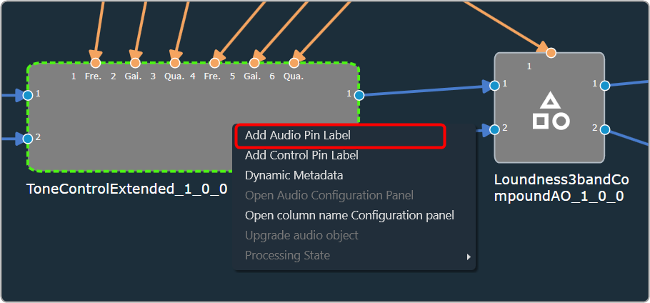
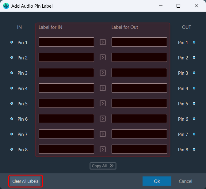
  1. On the signal flow designer, right-click on the audio object, and select Add Audio Pin Label. This opens the Add Audio Pin Label dialogue box.
    A picture containing graphical user interface Description automatically generated
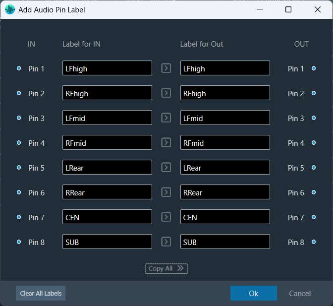
  2. On the pin label dialogue box, enter the input pin and output pin details and click Ok. The label will be displayed on the audio object.

Adding audio pin labels will propagate output pin labels to the next connected audio object input pin labels.

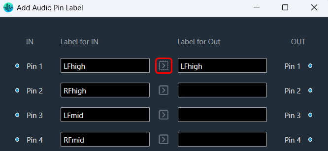
Also, you can use the “Copy” option to easily duplicate the label from each audio input pin to its corresponding audio output pin. This feature streamlines the labelling process, ensuring consistency across your connections and saving you time while setting up.
Simply, click on the “Copy” option for the audio input pin whose label you want to copy; the GTT will copy the audio input pin label to the respective audio output pin label.

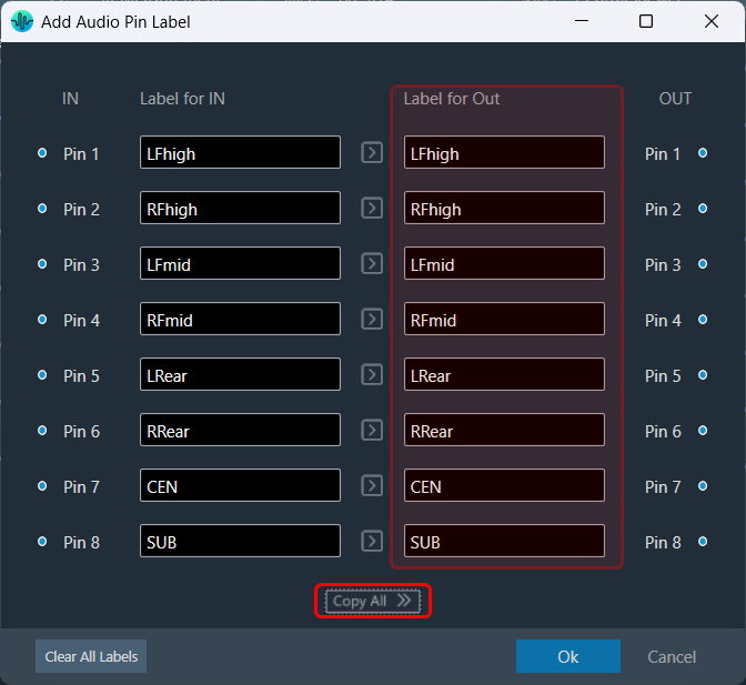
Similarly, you can use the “Copy All” option to copy all the audio input pin labels to the respective audio output pin labels.
The “Copy All” feature will prompt a user confirmation message before proceeding. If you respond with a “yes,” the GTT will copy all audio input pin labels to the respective audio output pin labels.
This ensures that the labelling is consistent and accurate across the board, making it easier to manage their pins effectively.

Selecting the “Clear All” option will display a confirmation message. If you choose “Yes,” all audio pin labels will be permanently removed, and this action cannot be undone.

Steps to Add Control Pin Label


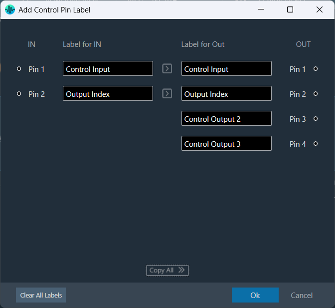
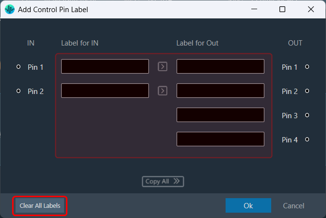
  1. On the signal flow designer, right-click on the audio object, and select Add Control Pin Label. This opens the Add Control Pin Label dialogue box.
  2. On the control label dialogue box, enter the input pin and output pin details and click Ok. The label will be displayed on the audio object.

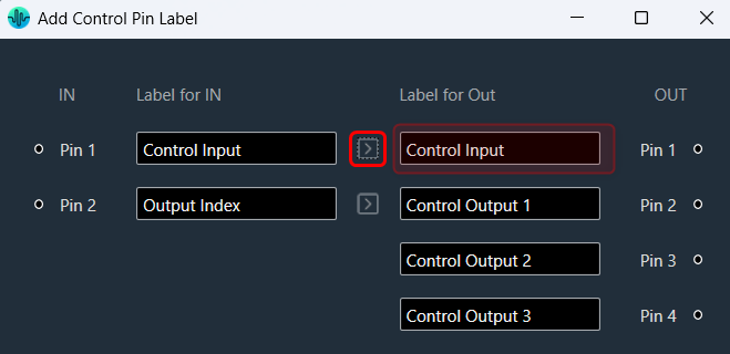
Also, you can use the “Copy” option to easily duplicate the label from each control input pin to its corresponding control output pin. This feature streamlines the labelling process, ensuring consistency across your connections and saving you time while setting up.

Simply, click on the “Copy” option for the control input pin whose label you want to copy; the GTT will copy control input pin labels to the respective control output pin label.

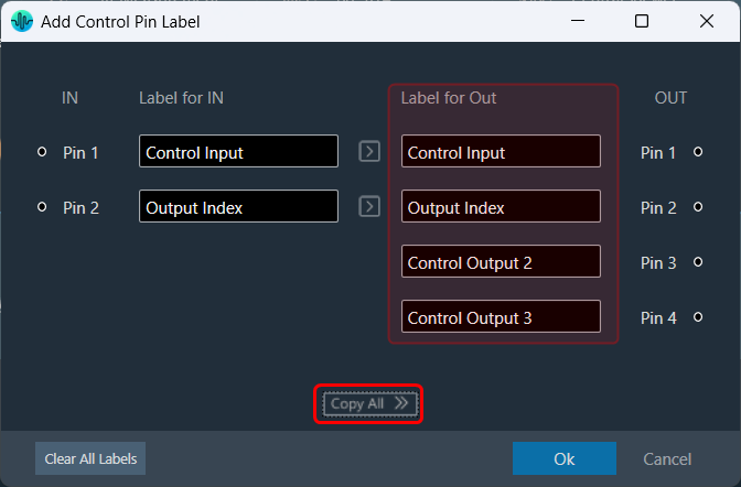
Similarly, you can use the “Copy All” option to copy all the control input pin labels to the respective control output pin labels.
The “Copy All” feature will prompt a user confirmation message before proceeding. If you respond with a “yes,” the GTT will copy all control input pin labels to the respective control output pin labels.
This ensures that the labelling is consistent and accurate across the board, making it easier to manage their pins effectively.

Selecting the “Clear All” option will display a confirmation message. If you choose “Yes,” all control pin labels will be permanently removed, and this action cannot be undone.

Tooltip


A tooltip is a graphical user interface (GUI) element that appears when you hover over pin connections. It typically contains a brief description or additional information about the pin connection. Tooltips can be used to obtain more detailed information on the connection between Audio Objects, Tooltips are available that display the affected AO names and the corresponding pins used.

To access these tooltips, you must connect any two audio objects first, then hover your mouse over the connection presenter (arrow). This will display a tooltip showing the Audio Object Name, Pin No, and Labels (if any) for the connected objects.
Graphical user interface Description automatically generated with medium confidence

Compound Audio Object Instance Pin Labels


The Compound Audio Object (CAO) instance takes pin labels from CAO audio objects such as CompoundAudioIO, CompoundControlIn, and CompoundControlOut, and applies these labels to the CAO instance when extracting or dragging a new CAO type from the toolbox.

It will swap In pin labels with Out pin labels for the CAO instance.

On Compound Audio Object upgrade the Compound Audio Object instance takes the latest CAO type pin labels and updates it in the CAO instance.

Tuning Panel Compound Audio Object

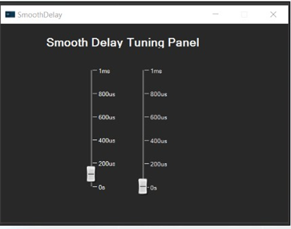
Compound audio objects are created by extracting audio objects from the signal flow. When the CAO is exported, both the compound audio object and the panel associated with it can be shared with others, and it is simple to tune when the CAO is imported. This section explains how to link a custom panel to CAO.

To link custom panel with Compound audio object:

  1. Open the GTT and create a Compound Audio Object. To create a Compound Audio Object follow the steps mentioned in the Create a Compound Audio Object section.
  2. Once Compound Audio Object is created, go to the Panel Designer tab to create a custom panel. To create custom panel, refer Create a Custom Panel in GTT section.
  3. Once the custom panel is created, go to the Signal Flow designer window and select the Compound Audio Object. This opens the property of the Compound Audio Object.
  4. On the Compound Audio Object property, check the Is Custom Panel option and select the appropriate custom panel from the list box.
  5. Double-click on the Compound Audio Object to launch the custom panel.

    There will be exclamation marks on the control if the state variables are not associated with the control. All exclamation marks must be fixed before proceeding further.
    Refer to Create a Custom Panel in GTT to link state variables to controls.

  6. Once the custom panel is verified, go to the Compound Audio Object property, and click on Link Custom Panel to CAO in Toolbox.
  7. Click Ok to confirm. Now the custom panel is linked with the toolbox type.

This option will be available only if the audio object selected is a CAO type.

Sharing Compound Audio Object

Once the custom panel is linked with the CAO, you can verify the link by dragging the CAO into the signal flow and double-clicking it. The panel should launch like any other audio object with default panels.

To share the compound audio object with others, export it as a .cao file, refer to Export a Compound Audio Object section.

If the .cao file contains a custom panel, it will be associated with the panel when the CAO is imported. CAO can be launched and tuned by dragging it into the signal flow designer and double-clicking it.

Editing Compound Audio Object

In addition, it is possible to make changes to CAO files that have exported as .cao files.

To include the CAO Custom panel to the list:

  1. Go to the Compound Audio Object property, and click on the Add CAO Custom panel to the list.

This will open up the edit custom panel window where you can make further modifications.

The edit option for “Add CAO Custom panel to the list” feature will be available only for CAO type only.

Tuning and Editing Compound Audio Object

Once you have created a compound audio object. You can perform the following actions on the compound audio object.

Edit a Compound Audio Object

To edit a Compound Audio Object:

  1. On the Signal Flow Designer window, select the compound audio object under the Compound Audio Object category in the toolbox and click Edit through the context menu. This opens the Compound Audio Object editor.
  2. On the Compound Audio Object editor, modify the configuration and tune the inner audio objects.
  3. Click Save, once the modifications are done.
    The compound audio object or tuning version is automatically incremented when you close the Compound Audio Object editor window. Tuning major version auto-increment happens for the below scenarios.

    • When an audio object is added or deleted.
    • When the inner connection changes.
    • When there is a change in the audio object configurations inside the Compound Audio Object.
    • When the Object mode/ Additional parameters change.
    • When an audio object channel numbers are modified.
    • When an audio object is upgraded.
    • When the inner Audio object tuning data is modified.
  4. Close the Compound Audio Object editor window to redirect to Device Signal Flow.

If the Compound Audio Object version is changed, the Compound Audio Object in the Device Signal Flow will be highlighted in a different color and must be upgraded in order to save signal flow. Right-click on the highlighted audio object and select the upgraded audio object from the context menu.

On major version upgrade of CAO, tuning data will be set to the default tuning data of the CAO template in the toolbox.

Compound Audio Object can be edited without affecting the current working Device Signal flow. This means that you can edit Compound Audio Object while connected to a device. It will not interfere with the current device configuration.

Using the Ribbon Button under the Signal Flow Designer tab, you can view the State Variable Explorer for the currently designed signal flow. The title of the State Variable Explorer window will be “CAOTemp_(CAOName).”

The CAO name is “Loudness3bandCompoundAO” in the image below. The “CAOTemp_” is the suffix that denotes a temporary explorer for CAO editing.

Edit Compound Audio Object Meta Data

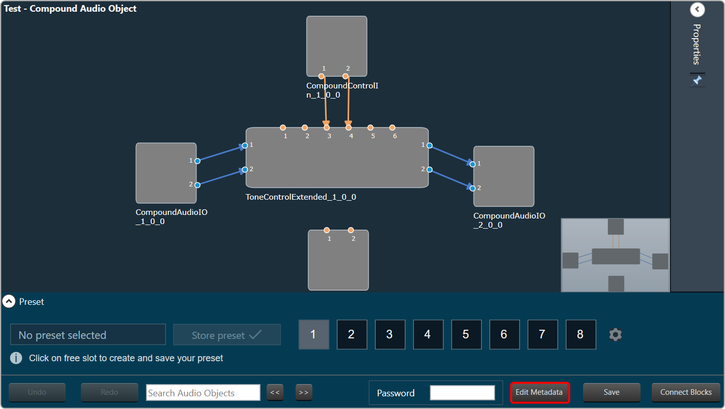
The Compound Audio Object metadata could be updated by clicking Edit Metadata in the compound Audio Object view.

To Edit the Compound Audio Object Metadata:

  1. On the Signal Flow Designer window, select the compound audio object under the Compound Audio Object category in the toolbox and click Edit through the context menu. This opens the Compound Audio Object edit view.
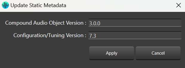
  2. On the Compound Audio Object editor, click Edit Metadata. This opens the Update Static Metadata dialog box.
  3. Edit the Compound Audio Object Version or Tuning Version.
  4. Click Apply to update the changes.

During creation, the Compound Audio Object version and the Tuning version are set to 01.00.0 and 01.00 respectively.

When editing, you have the option to update the version of the Compound Audio Object or Tuning Version based on your needs, and this information will be recorded by GTT.

Auto increment always works with the latest version available before saving. This means, that if the user edits the version before saving, the updated version will be auto incremented based on the above criteria.

Apply tuning to Compound Audio Object Template

Tuning a Compound audio object (CAO) in Signal flow can be performed live by connecting to the device. CAO inner audio objects can be tuned using custom panels, the state variable explorer, or set files.

By clicking Apply tuning data to Toolbox type, CAO instance tuning can be applied to the CAO template in Toolbox.

Metering a Signal Flow

The Metering functionality in a signal flow design basically measures the audio signal output and control output from an audio object of the discovered device.

The SFD metering feature is available from V release onwards and supports discovered devices.

The following audio objects are compatible with Control Metering functionality.
– LUT
– Control Math
– Control Smooth
– ControlMultiAdder
– ControlIn
– Control Grouper (Level meter is not usable on ControlGrouper’s control outputs until GTT supports level meter on BlockControl outputs)

To use this feature, you need perform following actions:

  1. You need to enable Streaming functionality in the device view and configure the parameters.
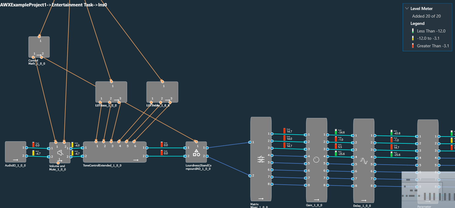
  2. Then, you need to add Level Meters in the signal flow design. When a device is connected, you can use Level Meter to monitor the audio output (Peak or RMS values) by adding them to the audio out connections. Similarly, control output value can be monitored in level meters for control out connections.
Enabling Streaming Functionality


In order to utilize Metering feature for each core, you need to enable Streaming functionality.

To enable Streaming functionality:

  1. Open the Device View and select the Virtual core layer of the device.
  2. Go the Virtual core properties and select the Streaming checkbox. This will enable the Streaming functionality.
    Additionally, in the Streaming functionality you need to configure the number of level meters that can be added in the signal flow to monitor control out connections or audio.

A core can be configured with up to 32 level meters, and by default it is set to zero. These values will be sent to device while sending device configuration to allocate required memory for level meter streaming.
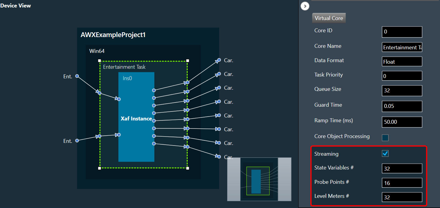
All level meters under a core will be deleted if the number of level meters you configure in device view is less than the total number of level meters added in a core.

If you modify any of the Streaming configurations, make sure to perform “Send Device Configuration” operation while connecting device.

Level Meter Panel


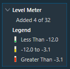
The Level Meter panel displays number of maximum allowed level meters, number of added level meters and the color coding for different ranges of audio output values.

If the streaming is enabled and the number of level meters configured for the core is greater than zero, a Level Meter panel appears in the top right corner of the signal flow designer.
By default, the Level Meter panel is collapsed.

Click on the expand option to view the Legend section. The legend section shows the color coding for various audio output value ranges in addition to the quantity of level meters.

  • Green – Peak/RMS value is less than -12.
  • Yellow – Peak/RMS value is in the range of -12 to -3.1.
  • Red – Peak/RMS value is greater than -3.1.
Configuring Level Meter in Signal Flow Designer


The Level Meter allows you to monitor the audio output and control output in the Signal flow design. In order to monitor you need to add Peak or RMS to the audio out and control out connections of audio objects.

Configuring Audio Output connection

You can view the peak or RMS value of each audio out connection by adding level meters via the connection context menu.

The Peak and RMS are computed based on current block only which means the block length chosen would decide the peak and RMS value. Shorter the block length more fluctuations in peak/RMS value.
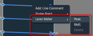
When the Peak option is selected from the context menu, a level meter will be added to the connection to display the connection’s peak output value.

When the RMS option is selected from the context menu, a level meter will be added to the connection to display the RMS value of the output in that connection.

The color of the connection changes when a level meter is added. The color of the connection indicates whether a level meter is present in that connection. The level meter color will get updated dynamically based on the Peak/RMS value of the audio output.

The level meter control and value will not be shown if the device is not connected.

After adding Peak or RMS level meter, delete option will be enabled in context menu. Even the type of level meter can be switched by selecting the enabled level meter context menu option(Peak/RMS).
You can use delete option to remove level meter from a connection. On deleting level meter, level meter control and value will be disappeared, and connection color will reset to default.
Configuring Control Output connection

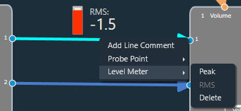
The Control output value of each control out connections can be viewed by adding level meters through context menu of the connection,
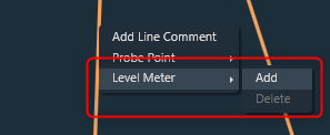
When the Add option is selected from the context menu, level meter will be added to the connection to show control output value of that connection.
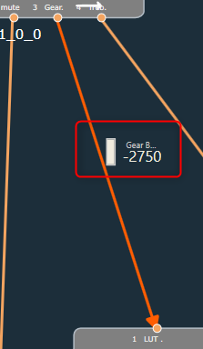
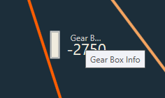
In addition to the control output value, the pin label will be displayed. A tooltip for the pin label has been added in order to see longer pin labels.
The color of the connection changes when a level meter is added. The connection color indicates the presence of level meter in a connection.

If device is not connected, level meter control and value will not be displayed.

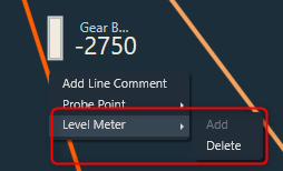
Once after adding level meter, delete option will be enabled in context menu.
You can use delete option to remove level meter from a connection. On deleting level meter, level meter control and value will be disappeared, and connection color will reset to default.
While configuring Level Meter in signal flow designer, you can Undo or Redo the Add, Delete and Switching Parameter (Peak/RMS) operations.

Keyboard Shortcuts

Keyboard shortcuts are available to add/delete level meters in signal flow designer screen. Following are the keyboard shortcuts available for different operations:

  • Ctrl+Shift+P – To add Peak Level Meter
  • Ctrl+Shift+R – To add RMS Level Meter
  • Ctrl+Shift+A – To add Control Out Level Meter
  • Ctrl+Shift+D – To delete Level Meter

Once one or more connections in the signal flow have been selected, the keyboard shortcuts can be used. This option makes it simple to add or remove multiple level meters.

Export and Import Level Meters

While exporting the project, the added level meters will be exported as part of GTTD file. On importing the project, exported level meters will be imported to GTT.

Delete all Level Meters

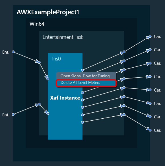
You can delete all level meters added in an instance by using “Delete All Level Meters” option in instance context menu. GTT will display a message after all level meters have been successfully deleted.
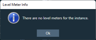
If no level meters are present, following error message will be displayed.
Level meter streaming will get stopped on disconnecting the device. On reconnecting the device, streaming will get resumed for existing level meters if SFD screen is active.

Level meters are not supported for below connections in V release:
– CAO output connections.
– Connections in CAO signal flow.
– Block control connections.

Tune a Signal Flow

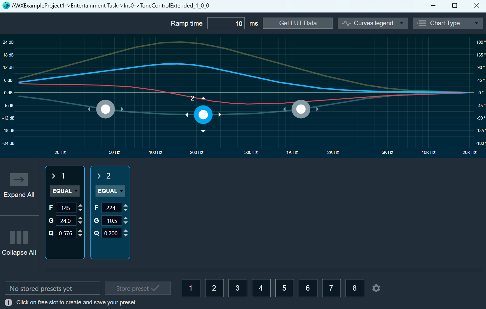
Native panel is one of the important elements of the Signal Flow Designer. The native panel has interactive widgets that help to tune complex audio objects easily.

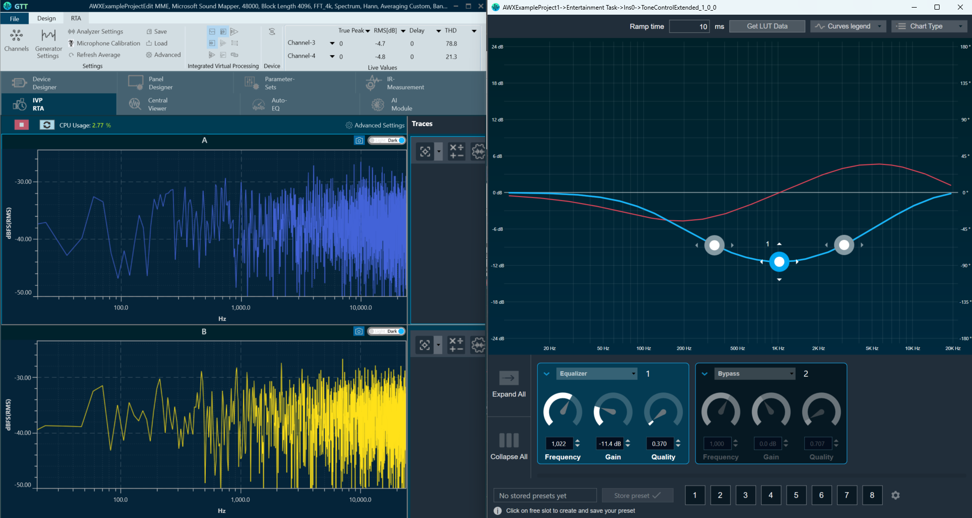
The tuning of a signal flow will be illustrated by showing the tuning effects on virtual devices in IVP RTA. RTA is a multi-channel Real Time Analyzer for audio signals. It provides time and frequency domain analysis tools to measure RMS/peak levels, frequencies, THD, delays, magnitude, and phase responses.

Launch Native Panel


  1. On the Signal Flow Designer window, double-click on any audio object to open a Native Panel.

    Use the interactive widgets on the Native panel to make the desired changes to audio object properties.

    When Native Panels is open, if there is any modification to Signal Flow Designer, a popup message will appear asking to save the changes.

    When Native Panels is open, you cannot make any changes to the Signal Flow Designer window. But you can open another native panel from the Signal Flow Designer window.

  2. If the preset bar is present in the panel, select the free preset slot numbers, enter the name of the slot, and click Store preset. This saves and stores the current tuning data to the selected slot.

If you do not enter a name of the slot, then it will take the default named “New Preset”.

You can switch between presets and apply their values to the native panel by simply clicking on them. You can also change the values in the native panel or the preset name after you have clicked it to override the preset.

You can reset the selected preset or all the preset.

  • Click Reset Selected to clear the preset that is currently selected.
  • Click Reset All to clear every preset in the corresponding native panel.

Visualize a Signal Flow


You can check the tuning effects of the designed audio signal flow on the virtual device in IVP.

For more information, refer to Analyzer and Generator.

Perform Tuning


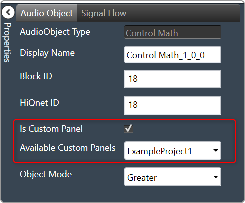
The audio objects that do not have their own native panel can create a custom panel and link the panel with the respective audio object.

If an audio object doesn’t have its own native panel, you can create a custom panel and link it to the appropriate audio object under the “Available Custom Panels” option.
Graphical user interface, application Description automatically generated

Follow the below steps to view the signal flow performance:

  1. Go to the IVP tab, start Generator, Analyzer, and Plugin Host.
    For more details about Generator, Analyzer, and Plugin Host settings, refer to the Real Time Analyzer User Guide.
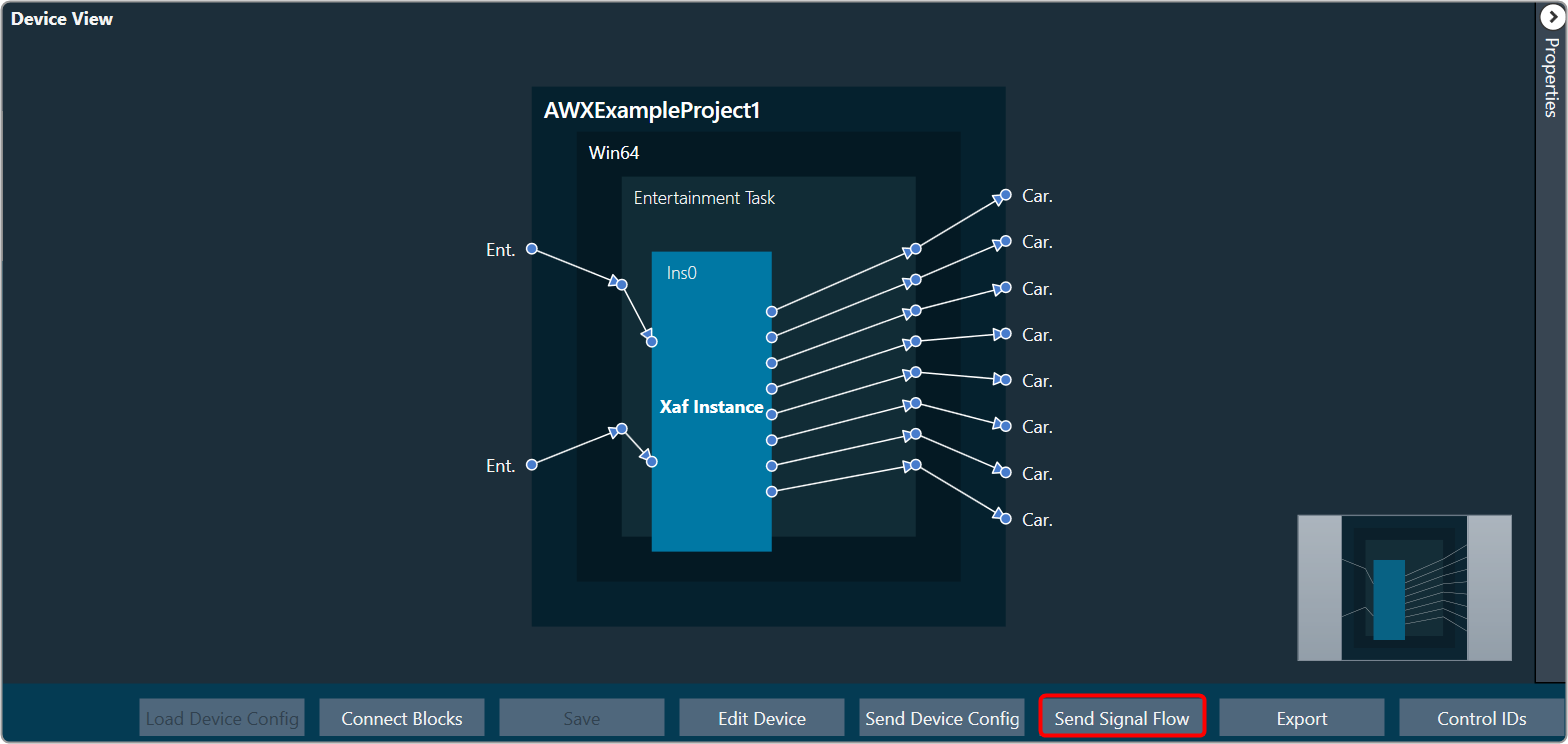
  2. Go to the Device Designer tab, click on Send Signal Flow to send tuning data.
    A screenshot of a computer Description automatically generated with medium confidence
  3. Open the native panel and go back to the IVP window.
  4. On the native panel, tune the signals. The signal flow in the IVP tab will change accordingly.

View Audio Object Metadata

In the Signal Flow Designer, you can view static metadata and dynamic metadata of an audio object.

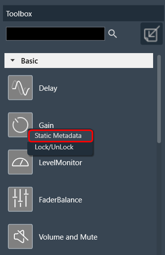
Static Metadata


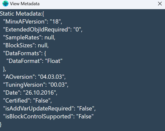
Static metadata refers to the metadata information of an audio object that does not change frequently. By default, every object available in the toolbox has the static metadata. Right-click on the audio object in the toolbox section to view the static metadata details.

On the metadata dialog box, the following metadata information displayed.

Dynamic Metadata


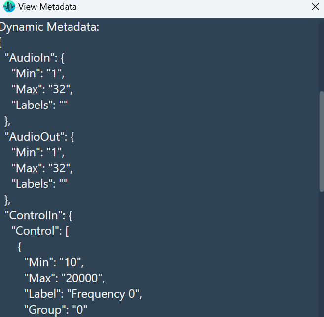
Dynamic metadata includes metadata information of an audio object that changes frequently or is generated in real-time. Every audio object instance in the signal flow designer has dynamic metadata. Right-click on the audio object in the signal flow designer to view the dynamic metadata details.

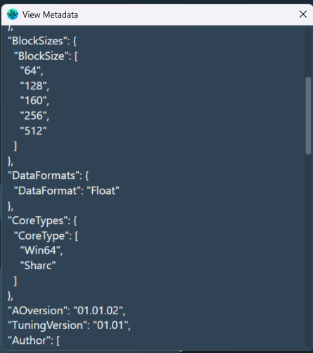
On the metadata dialog box, the following metadata information displayed.

Metadata will also show which core types of the audio object supports.  If the CoreTypes node is blank, this indicates all core types are supported.

Open column name Configuration Panel

When linked to an object, the Smart LUT feature automates the process of adding column labels semi-automatically rather than manually.

The “Open column name Configuration Panel” feature only supports LUT audio object.

Launching Column Name Panel


You can use this feature to choose which state variable values should be shown as column headers on the LUT panel. To begin assigning state variables to the columns of the LUT panel, simply open the panel by accessing the context menu of the LUT object in the SFD.

SFD must be saved before opening this feature else the state variables will not be available.

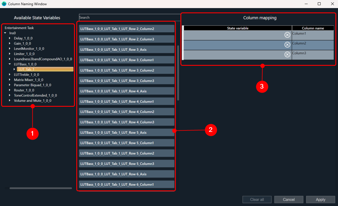
Following are the components available on Column Naming Window.

  1. Tree with all objects
  2. List with columns details

State variables associated to different objects

State variables can be filtered in two ways:

By clicking on the individual audio objects in the tree – each click will display the state variable of the respective audio object. Multiple objects can be selected to display their state variables.

Or

Use the Search bar and type required text, for example AO name (not case sensitive).

Selecting State Variable


Each state variable can be assigned to only one column. After assigning to column, it will disappear from available state variables.

To assign state variables to a column, select the state variable and drag it to the appropriate column.

  • To Select: Multiple state variables can be selected by holding the CTRL key or by clicking the ‘Select all’ button above.
  • To Move: For moving selected variables, use the SHIFT key to hold and move the variables.

When all columns are completed, the ‘Apply’ button in the bottom right corner will become active. It will also be enabled if all columns are empty.

To stop using state variables for naming it is necessary to open the Naming panel, clear all variables and apply.

Workaround for LUT Parameter Sets Unit Problem


This workaround is required for projects which are exported earlier than N+1 release.

  1. Import earlier exported project and open Signal Flow designer.
    • If all LUT objects belong to the same group, double-click on any LUT objects to launch the panel.
    • If each LUT object belongs to different groups, then launch the panels separately for each group.
  2. Close the LUT panels.
  3. Open Parameter sets view, right-click on column header of red color highlighted set and click ‘Store’ context menu to get latest set values.
    You can observe the red highlights are cleared and units are removed for each state variable.

Upgrade Audio Object

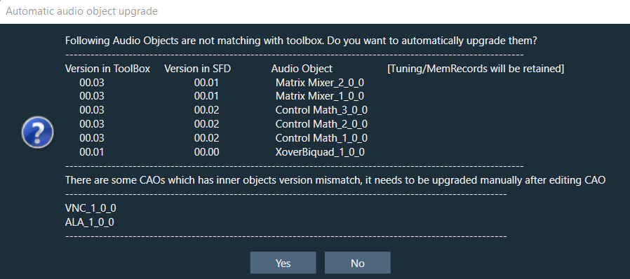
When you launch signal flow designer by double-clicking on the Framework Instance in device view, GTT validates all audio objects that are mismatching with the toolbox. A report is displayed with the version difference of all audio objects, with the option to auto-upgrade them based on the user’s preferences.

  • If you select “Yes”, all audio objects will automatically be upgraded to the version equivalent to the toolbox version. If any compound audio objects exist. They must be upgraded manually.
  • If you select “No”, the signal flow will be launched, and you need to manually upgrade them.
  • If the audio object in the signal flow design becomes out of sync as a result of modification. The compiler report will display a warning message, and the audio objects will be highlighted in blue.

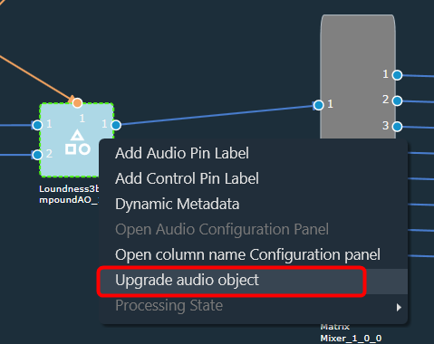
To manually upgrade the audio object to the signal flow designer state; right-click on the highlighted audio object and select “Upgrade Audio Object” from the context menu.

Until N-release, if any audio objects are out of sync with the audio library, GTT will not allow you to save or send the signal flow to a device. To pass the validation, you must manually replace (delete) the current audio objects in the signal flow with the toolbox audio object. All connections and tuning data are lost during this process, which must be redone, resulting in increased effort.

The below image shows the context menu option to choose “Upgrade Audio Object”. When the audio object is upgraded, there will be messages to guide you to the next steps.

The following audio object properties will be upgraded:

  • Additional variables (added or deleted)
  • Modes (added or deleted)
  • Audio object properties like input/output, channels, etc
  • Tuning version

The audio objects with major tuning version changes or structural changes, such as additional variable changes, will be detected as incompatible and highlighted in blue. Until all these incompatible AOs are upgraded, signal flow cannot be saved.

Version changes in Tuning will be highlighted in blue and until all these AOs are upgraded, signal flow cannot be saved.
Tuning data and Parameter sets will be preserved in case of a Minor version change while in case of a Major version it will not retain data

Example: When the tuning version of an audio object in the signal flow is 04.00 and the version in the toolbox is 04.01, only the minor version has changed. As a result, the tuning data will be saved.
Similarly, if the tuning version of an audio object in the signal flow is 04.00 and the toolbox version is 05.00, tuning data will be lost because the internal structure of the AO has changed.
When the upgrade is complete, a message will appear informing the user of the tuning data status.
Graphical user interface, application Description automatically generated

The above message is a warning that there may be a tuning data loss because the audio library changed the major version in the tuning version. The set group(s) to be modified will be listed in the message.
If no set groups are created using the respective audio object, the following message will be shown.
Graphical user interface, application, website Description automatically generated

Upgrade Compound Audio Object (CAO)


The compound audio object (CAO) in the signal flow can also be upgraded. For minor version changes, only the version number will be updated, but no other changes will be made. However, in the case of a major version change in the toolbox, the internal audio object will be updated to the latest version according to the CAO type in the toolbox.
If there is a major version change and the inner objects cannot be automatically upgraded, the CAO will be marked with a blue color and then you need to upgrade the CAO.

For more details about the compound audio object, refer to the Compound audio object.

To upgrade the Compound audio object, follow the below steps:

  1. On the Signal Flow Designer window, select the compound audio object under the Compound Audio Object category in the toolbox and click Edit through the context menu. This opens the Compound Audio Object editor, where you can view the signal flow of the internal audio objects.
  2. On the Compound Audio Object editor, right-click on the highlighted audio object, and select Upgrade Audio Object from the context menu.
  3. Click Save and close the Compound Audio Object editor.
    After this modification, the CAO in the signal flow design updated and highlighted in blue color.
  4. Right-click on the highlighted compound audio object and select Upgrade Audio Object from the context menu.
    Once the CAO is successfully upgraded, the GTT will notify you.

Upgrading the block ID will not support if it is changed from normal format to extended format in the DLL.