The measurement tab consists of five sections.
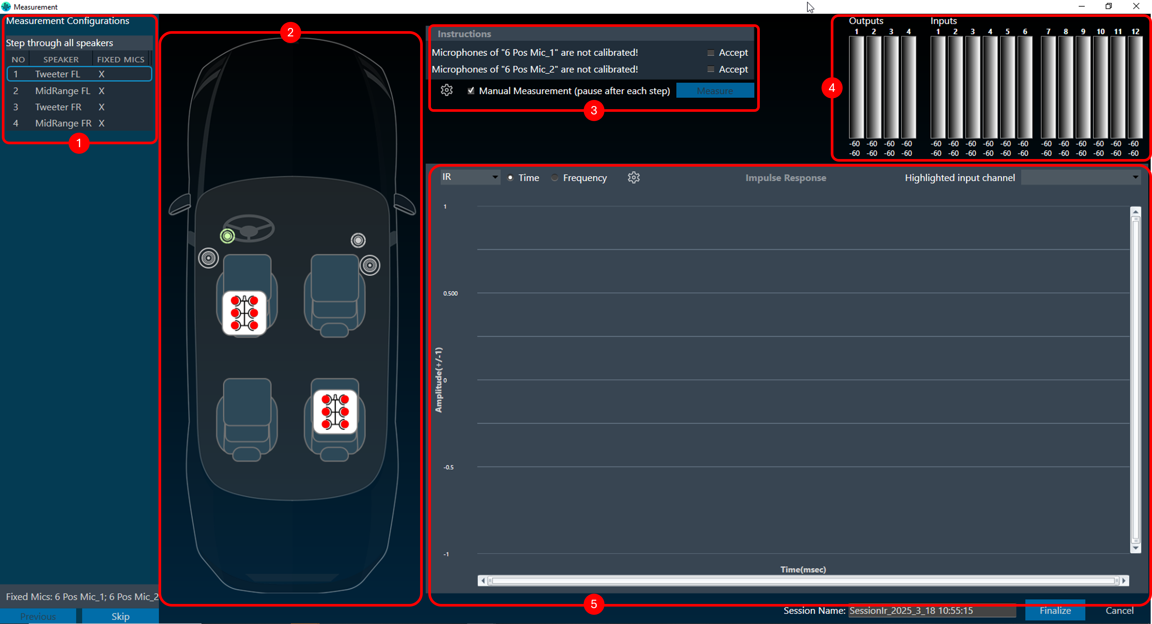
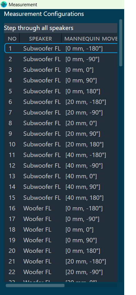
- Measurement Configurations: This section displays the measurement sequence list of all the measurements included in this session. The measurement number indicates the order in which the measurements will be performed. If the measurement is defined with the Mannequin Mic array, the measurement sequence list will include the movement information for each step. The physical mannequin will be initiated before starting acquisition, and acquisition will begin once the movement is completed.
- Speaker and Microphone Layout: This section shows the layout of the speakers and microphones on the selected car.
- Instructions: This section contains microphone calibration warnings and suggestions to relocate microphones.
- Signal Noise Ratio Settings: The settings button in highlighted area 3 displays the
Signal-to-Noise Ratio (SNR) Settings dialog, where SNR validation can be:- Enabled or disabled SNR,
- Can stop the measurement if SNR fails,
- Can set the SNR threshold value.
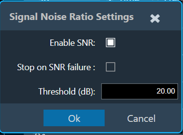 You can update from 0 to 98 dB as the threshold value. In case of SNR validation success, below message will appear.
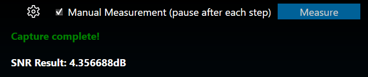 In case of SNR validation failure, below message will appear.
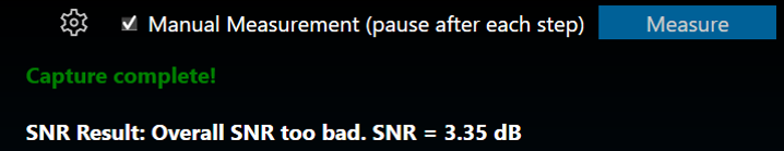
SNR validation will occur only if a single speaker is measured using the sync IR measurement type.
- Signal Noise Ratio Settings: The settings button in highlighted area 3 displays the
- Inputs/ Outputs: This section shows the current input and output levels using the meters.
- Measurement Inspection viewer: This section displays the result of each measurement.
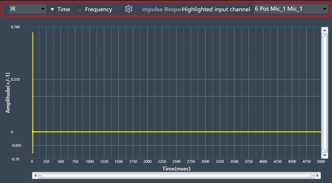
You can highlight a channel by selecting the channel from the ‘Highlight input channel’ drop-down menu.
The Measurement Viewer loads with default settings. You can change the viewer settings using the Settings icon.
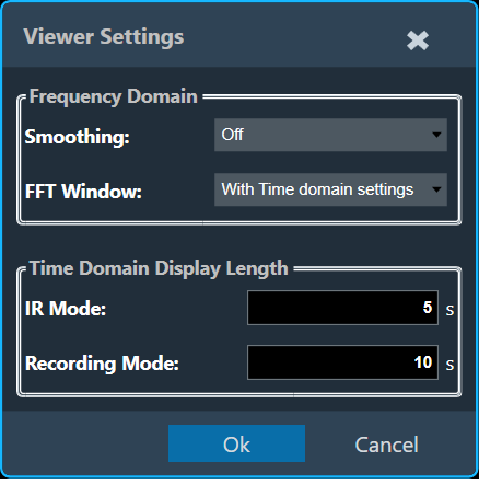
Viewer Settings Properties
The Viewer Settings window contains the following options, which are saved on an application-wide basis.
| Properties | Description |
| Frequency Domain |
|
| Time Domain |
When Generator Mode is selected for recording, IR mode will be disabled.
|