Define Mannequin Measurement

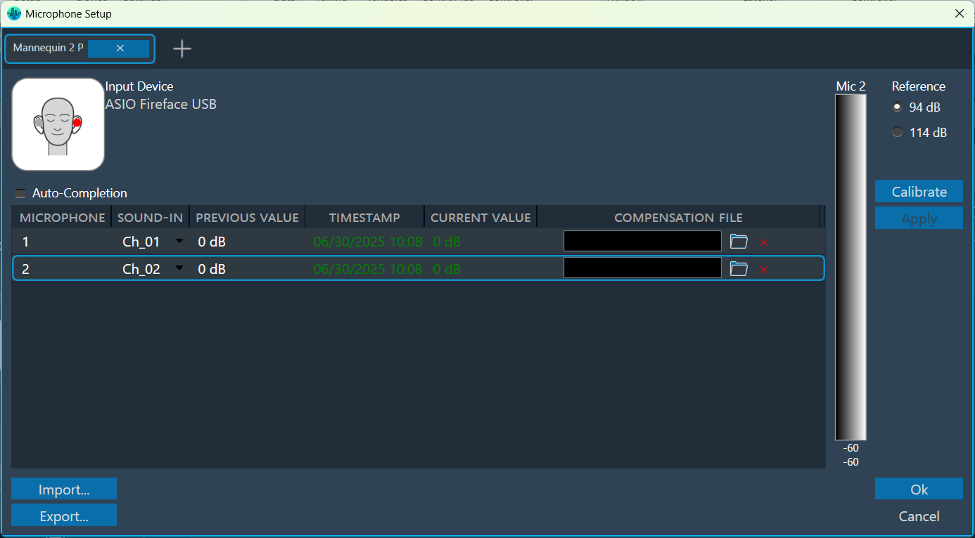
The seat measurements can be performed using a mannequin equipped with two microphones placed in the left and right ears.
The process to define a mannequin measurement is the same as that for other microphone arrays, with a few additional steps required to specify movement or rotation details for each sequence.

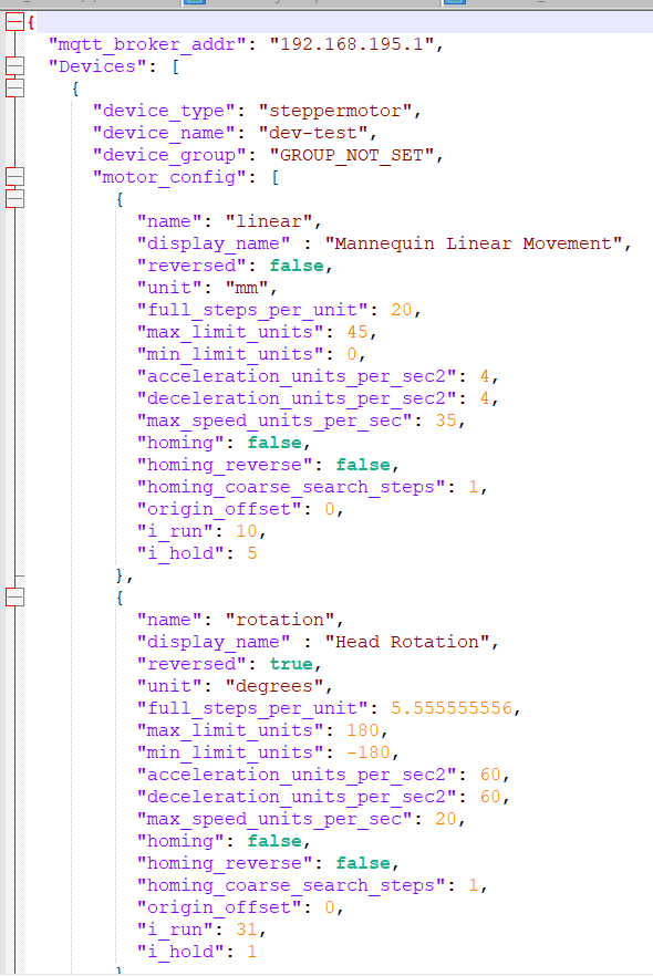
Mannequin Configuration file: Harman AudioworX has established a file template to enable mannequin movement and rotation functionalities. This includes defining minimum and maximum limits for rotation or linear movements, specifying their units, and providing the MQTT broker address necessary for motor communication and execution of mannequin movements.

Download Mannequin Config Template

Steps to configure Mannequin measurement:

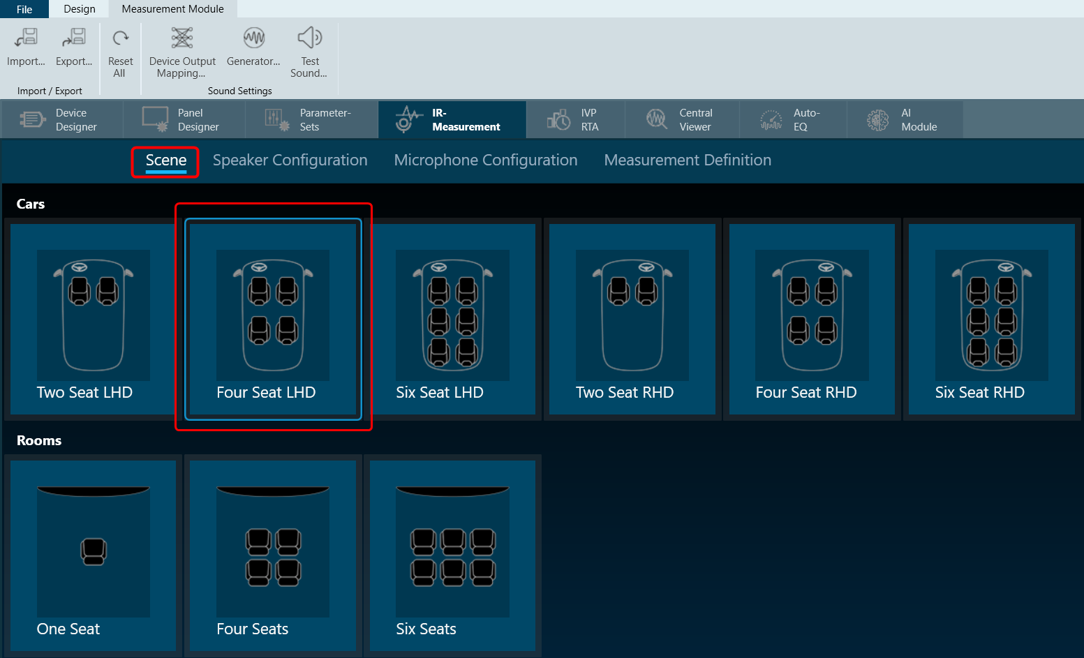
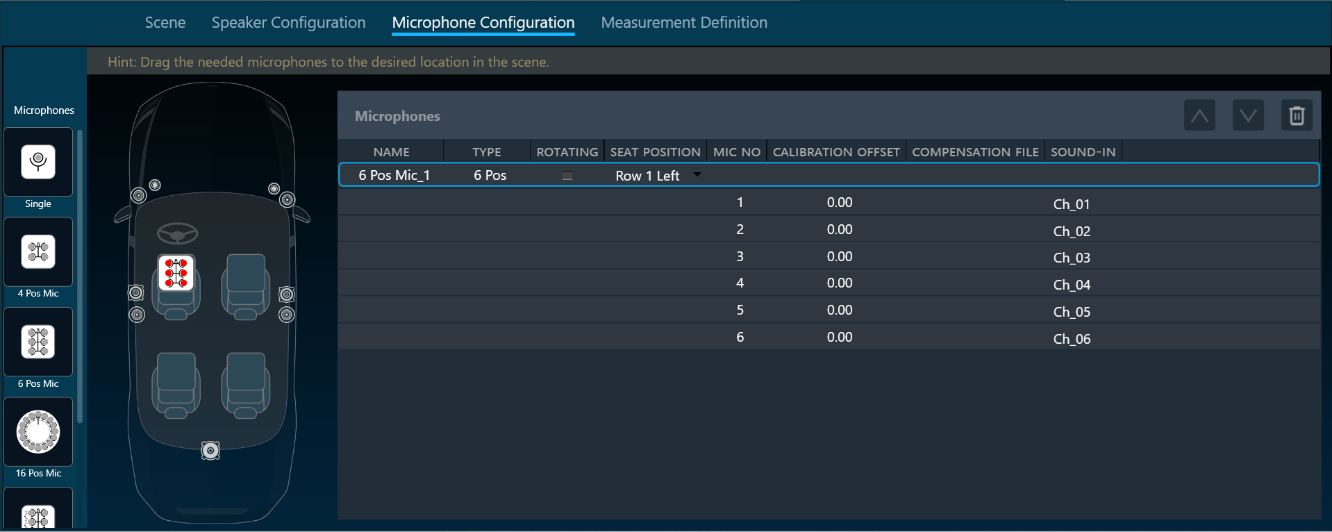
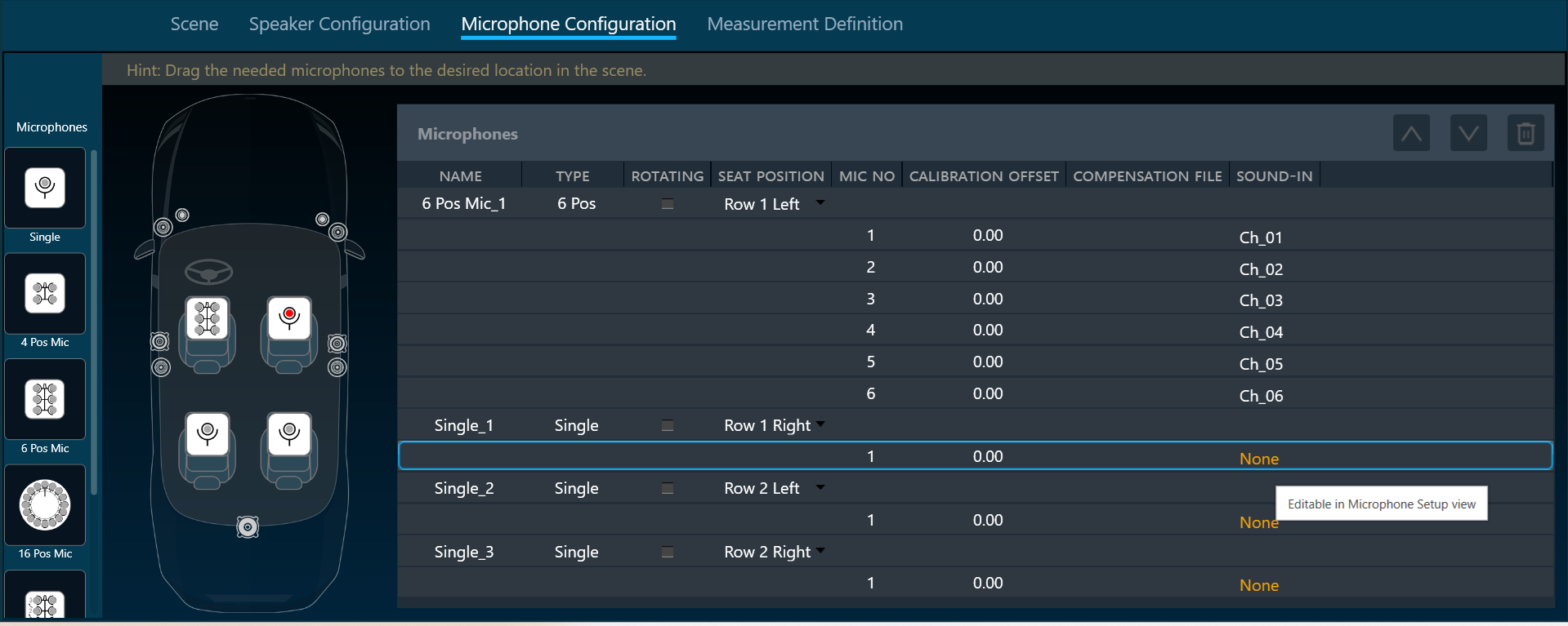
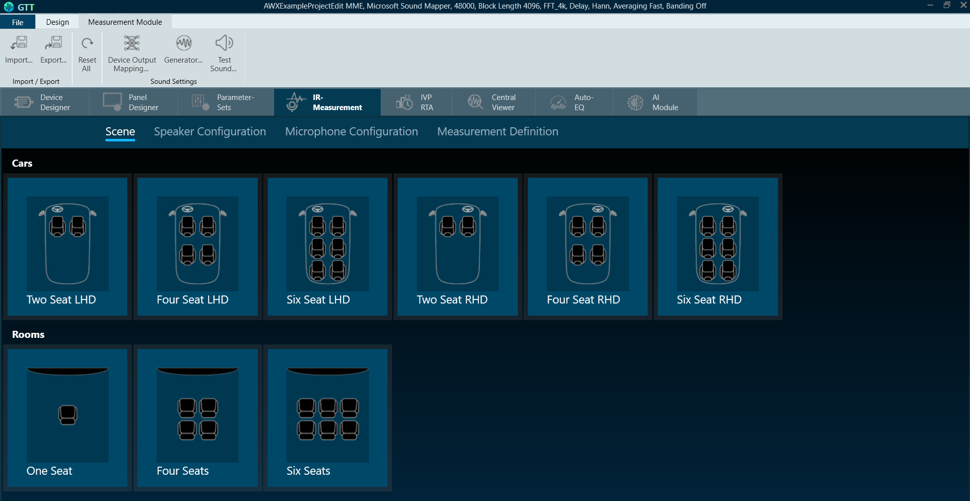
  1. In the microphone setup, select the mannequin option. The mannequin microphone array setup follows the same procedure as microphone arrays.
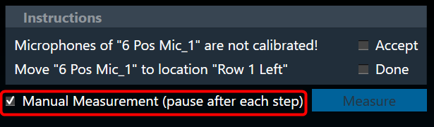
  2. On the Mannequin Measurement, follow the same procedure as the microphone measurement with a few additional steps. For more details, refer to understand measurement process.
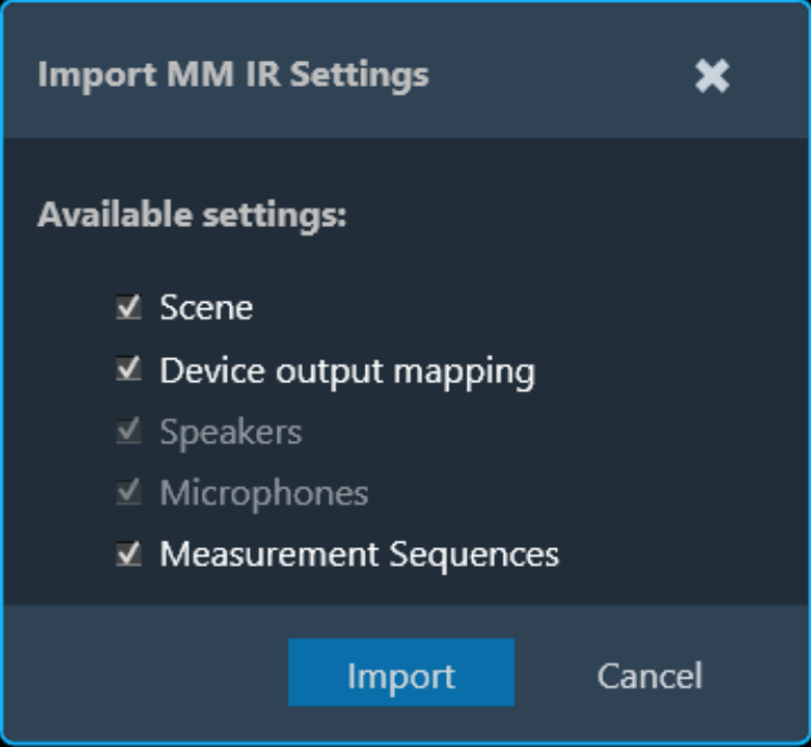
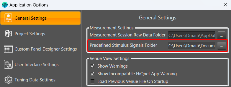
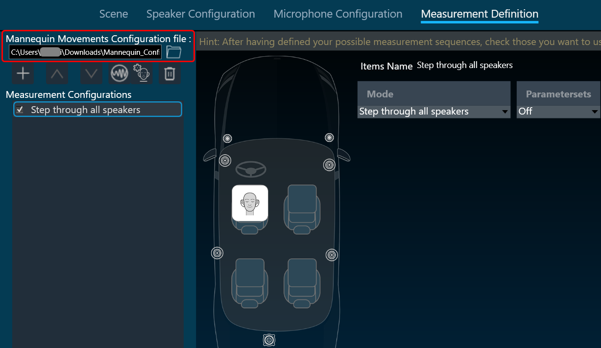
  3. On the Measurement Definition, select the browse option and open the “Mannequin template file.
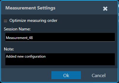
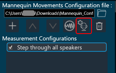
  4. Select the Mannequin Setting to configure mannequin movements.
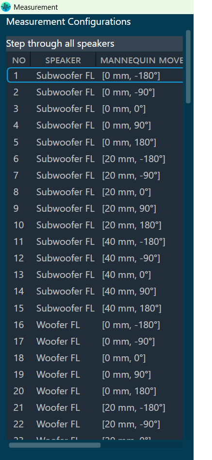
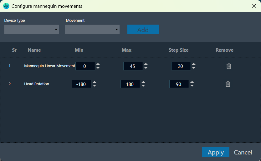
  5. In the Mannequin dialog box, the details of the configuration file selected in the previous step are parsed, and the available movements along with their minimum and maximum values are listed here. You can select the required movement and configure its minimum, maximum, and step size values within the provided limits.
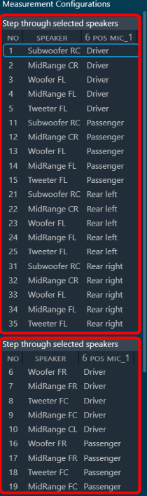
    Based on this configuration, measurement steps for each sequence will be generated.
  6. Once the Mannequin configuration is done, configure the remaining Measurement Definition.
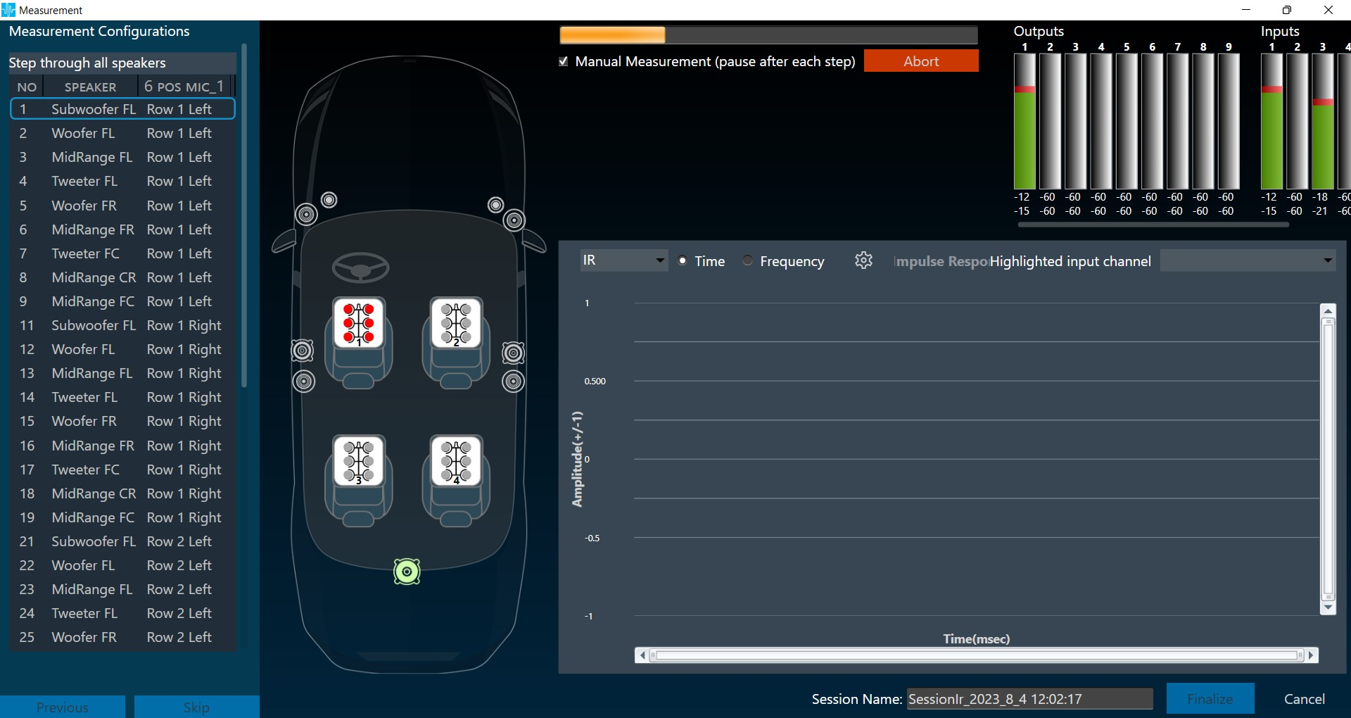
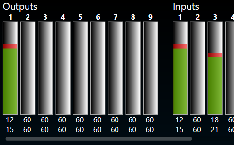
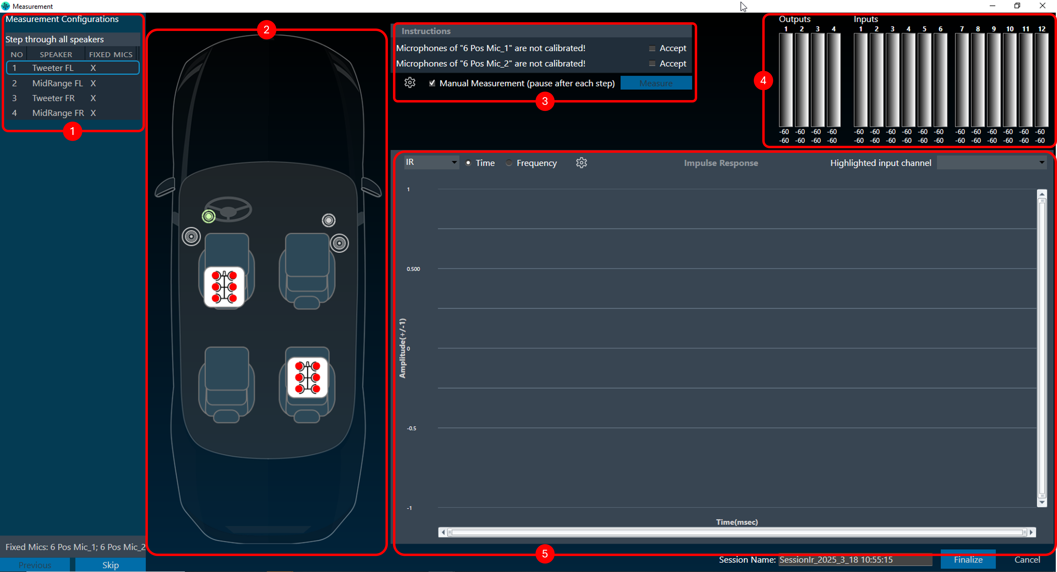
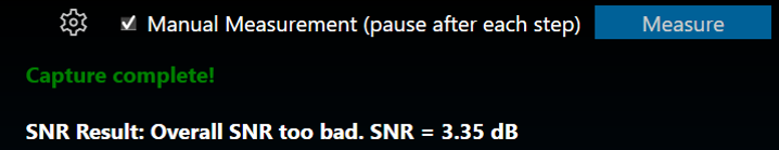
  7. Once you have configured all the measurements, click on Start Measurement Session to activate the measurement mode.
    This opens a new measurement window. For more details, refer to the Measurement Session.

Performing Measurement

Prerequisites

  • Ensure that the required car is set in the Scene tab; for more details, refer to Scene Setup.
  • Ensure that the speaker setup is configured in the Speaker Configuration tab. For more details, refer to Speaker Configuration.
  • Ensure that the microphone setup is configured in the Microphone Configuration tab. For more details, refer to
    Microphone Configuration.
  • Ensure that you define all measurements, set the mode and parameters, and check the measurement sequence in the
    Measurement Definition tab, for more details, refer to Measurement Definition.

Steps to Perform Measurement Session

  1. Once all the measurement configurations are done as described in the prerequisites, click on the Start
    Measurement Session.
    This will activate the measurement mode.
  2. Enter the session name on the Measurement Setting dialog box, add a Note (optional), and click Ok.
    If you want to optimize the measurement order, select Optimize measuring order. The
    optimization of the measurement order applies when several sequences with different loudspeakers are defined for
    at least one rotating microphone.

    – If no optimization is applied, the measurement will be performed independently for each sequence, resulting in
    the rotation of the microphone over all the seats within each sequence.
    – When optimization is applied, all the measurements that are linked to a seat position are performed one after
    the other, regardless of the sequence to which they belong.
    For large numbers of sequences, this greatly minimizes the number of microphone repositioning.
  3. The measurement module acquisition window will now open as a pop-up window, allowing access to tuning panels in
    the signal flow without obstruction. This enables manual muting and unmuting of necessary speakers through
    panels during measurement acquisition, especially in cases where automatic measurement isn’t feasible.
  4. Once the window opens, the following operation will happen.
    1. In the measurement configuration section, the measurement will start sequentially. After completing
      measurements are displayed in green, and aborted measurements are displayed in red.
      A computer screen shot of a computer Description automatically generated
      In the example below, two “Step through selected loudspeakers” sequences are about to be performed. Due to measurement optimization, the two driver seat measurements will be performed immediately after each
      other, as indicated by measurement numbers 1 and 2.
      A screenshot of a computer Description automatically generated
    2. In the instructions section, a warning is displayed regarding microphone calibration and microphone
      relocation.
      To begin, select the appropriate checkbox. After confirming all instructions, click Measure to start the measurement.
      If you want to stop after each measurement, then select the Manual Measurement (Pause after each
      step)
      option.
      A screenshot of a computer error message Description automatically generated
      This stopped time can be used to further inspect the result in the viewer in the time (max is 5s for IR
      and max 10s for recording) or frequency domain as impulse response (IR) or pure recording.
      During a pause, you can trigger a repetition of the last measurement or skip the next measurement from the sequence list.
      – To repeat the last measurement, click Previous.
      – To skip the next measurement, click Skip.
      Repeating a measurement automatically disables the automatic measurement mode. It can be re-enabled at
      any time.
      A blue square with a cross Description automatically generated
      A pause is automatically activated when the measurement requires user action, e.g., the placement of a
      microphone on another seat.
    3. In the Inputs/ Outputs section, the current input and output levels are shown using the meters.
      A screenshot of a computer Description automatically generated
      Once the actual acquisition is complete and the measurement is only being post-processed, the message “Capture complete! ” appears in the instructions box.
      The result of each measurement is displayed in the Measurement Inspection viewer section.
  5. After completing the measurement, you can navigate between steps by clicking on the previous and skip buttons to view the measurement for the selected step on the chart.
    • The chart will be blank if a step was unsuccessful or did not contain information to display.
    • On the Measurement Inspection viewer, display the result of each measurement.
      A computer screen shot of a car Description automatically generated
  6. Once all steps of the measurement procedure are completed, click Finalize to store the measurement.

You can rename the session at any point during the measurement. Click Cancel to discard the measurement

Generally, you can exit the Measurement window only when a session is cancelled or finalized.

The following actions are restricted during a measurement session:

  • Opening Sound Card Configuration in IR Measurement
  • Opening Device Output Mapping in IR Measurement
  • Opening  Generator Settings in IR measurement
  • Opening  Reset all in IR measurement
  • Opening Import in IR measurement
  • Opening  Test Sound in IR measurement
  • The “Start Measurement Session” button is disabled
  • Application Exit
  • New Project Import
  • New Project Create
  • Delete Project
  • Open Project
  • Save and Go Back in SFD
  • Save in Device View

If you try to perform any one of the above actions, a message will be shown “Measurement session in progress”.
A yellow rectangle with black text Description automatically generated

MM IR 2.0 – Test Sound

The Test Sound menu is used to set the parameters for the test sound.
The test sound is available on the speaker configuration tab and serves the purpose of quickly verifying the correct connection to a speaker selected in the speaker table. A generated sweep, or one of the predefined Async measurement signals (see “Generator”) can be used for the speaker test. The playback is limited to 2 seconds.

The following parameters can be set in sweep mode:

  • Gain: Playback gain in dBFS, only integers can be specified, positive values will be correct to negative

The following parameters can be set in predefined mode:

  • Gain: Playback gain in dBFS, only integers can be specified, positive values will be correct to negative
  • Selected signal: Choice of predefined signals

MM IR-Scene

The Measurement Module guides through each step to perform a measurement. Select and configure a Scene

  • The “Scene” screen displays various measurement scene options like  a left-hand drive car with two seats or inside a room.
  • Selecting a scene here impacts two things:
    • The number of available microphone positions. This depends on the chosen scene like a two-seater car will have fewer microphone positions than a five-seater).
    • Microphone position numbering: This is based on the driving position (left to right for left-hand drive, vice versa).

Once you double-click on the desired scene, the “Speaker Configuration” window will open.

MM-Microphone Configuration

Microphone setup tasks such as calibration, channel selection, and mic compensation file selection can be done using the Mic Setup view, either before or after the microphone configuration on the car.

On the Microphone Configuration view, you can arrange and configure the microphone.

The available microphone arrays are located to the left side on the Microphone Configuration view .

  • Single Microphone
  • 4 microphones
  • 6 microphones
  • 16 microphones
  • 4 by 4 array (to measure at 16 different microphone positions using 4 microphones in 4 steps at one array position)

You can perform following actions on Microphone Configuration window:

Positioning Microphone Arrays

  • You can freely drag and drop microphone array anywhere in the scene.
  • Dragging an array far outside the scene will remove it.
  • If the same mic array is already configured in the Mic Setup view, the name, channel assignment, calibration, and compensation will be used from the Mic Setup view. Any changes made to the respective mic array in the Mic Setup view will also be applied to the dragged mic array.

Seat Position Assignment

  • The mic array can be assigned to any available seat positions based on the selected scene. For example, in a 4-seat scene, the available seat positions are “None” (no fixed seat position), “Row 1 Left”, “Row 1 Right”, “Row 2 Left”, and “Row 2 Right”. Depending on the selected seat position, the mic array is placed in the car. If “None” is selected, the mic array will be placed at the position dragged by the user.

Managing Microphone Arrays

  • A list of all microphone arrays in the scene is displayed on the right.
  • Use the up and down arrows to change the order of the arrays in the list.
  • Mic Array name is only editable in Mic Setup view.
  • Click the delete button to remove an array from the list.

Soundcard Input Assignment

  • Assigning a Sound-In stream channel to each microphone is only allowed in the Mic Setup view.

Rotating Microphone Arrays for Sequential Measurements

  • Select “Rotating” for microphone arrays in the list to design a measurement sequence quickly.
  • These arrays will automatically snap to each seat, acting as a mobile unit that captures audio at multiple positions.
  • The seats will be numbered consecutively, indicating the measurement order.

The number of seats needs to be a multiple of the number of microphones in the rotating array.

  • You can keep additional microphones on the scene as fixed positions for more comprehensive data collection. The placement logic for the rotation is as follows:
    • One mic all seats in order: driver (seat 1), passenger (seat 2), rear behind driver (seat 3), rear behind passenger (seat 4).
    • Two mics, two seat car: mic 1 on seat 1, mic 2 on seat 2.
    • Two mics, four seat car: mic 1 on seat 1, then on seat 2, mic two on seat 3 then on seat 4.
    • Two mics, six seat car: as for 4 seats plus mic 1 on seat 5 (driver side), mic 2 on seat 6.
    • Three mics, two seat car: forbidden.
    • Three mics, four seat car: forbidden.
    • Three mic, six seat car: mic 1 covers first row, mic 2 2nd, mic 3 3rd. First all on the driver, then on the passenger side.

MM IR 2.0 – Startup

The Measurement Module is used to perform synchronous and asynchronous impulse response measurements and recordings.

If you want to work with the Measurement Module, you don’t need an active project. GTT will automatically create da ummy project, where you can perform all the operations. In case there is an active project available, the Measurement Module session will be associated with it.

A device is not necessary for the Measurement Module to function in the project. The Measurement Module enables direct sound card measurements without an intermediate device, whereas tests controlled by gain channels can be carried out via a device.

Related Topics

MM IR-Settings

The Measurement ribbon consists of the following groups.

  • Import/Export: Using the Import and Export option you can configure the import and export setting of the measurement module. For more details refer, to Import and Export Settings.
  • Reset All: Using the “Reset All” option you can reset parameters used for the measurement setup (scene, speaker mapping, mic mapping, and measurement session).
  • Sound Settings: In the Sound Settings group you can configure Device Output Mapping, Generator, and Test Sound settings. For more details refer to Sound Settings.

The entire ribbon bar will not function once a measurement session is active, it will re-function after it ends since the settings made here do not affect an active measurement session.


Import and Export Settings


Import MM IR Setting

The import menu allows you to import parameters available in the specified file.
Following are the parameters you can import.

  • Chosen scene
  • Device output mapping
  • Configured speakers
  • Configured microphones
  • Defined measurement sequences

These settings can be imported individually or together. Only the selection of the sequence import forces the import of speakers and microphones to guarantee consistency.
The import for the device output mapping will throw a warning if the project does not match the original project.

Export MM IR Settings

The export allows you to export all setup-related parameters.
Following are the parameters you can export.

  • Chosen scene
  • Device output mapping
  • Configured speakers
  • Configured microphones
  • Defined measurement sequences

These settings can be exported individually or together. Only the selection of the sequence export forces the export of speakers and microphones to guarantee consistency upon re-import.

Sound Settings


In this group, you can configure Device Output Mapping, Generator, and Test Sound parameters. These menus are accessible during every step of the measurement preparation.

  • Device Output Mapping: The device output mapping menu allows for the mapping of gain channels to device output channels.
  • Generator: The generator menu is used to define parameters for the signal used in measurements. Using the drop-down option you can select Generator mode.
  • Test Sound: The Test Sound menu is used to set the parameters for the test sound.

MMIR-Generator

The generator menu is used to define parameters for the signal used in measurements. Using the drop-down option you can select Generator mode.

The generator supports the following mode.

Synchronous Mode

The following parameters can be set in synchronous mode:

  • Stimulus length: Duration of the signal in seconds used to measure.
  • Silence after stimulus: Stop margin after end of playback, to capture the tail of the sweep signal also in very reverberant environments or over long distances. Takes decimal values.
  • Number of repetitions: Number of measurement tools will be, used for average measurement.
  • Gain: Playback gain in dBFS, only integers can be specified, and positive values will be correct to negative.
  • Override start frequency: If checked, the value entered for “Start frequency override” takes precedence over individual loudspeaker settings on the speaker configuration tab
  • Start frequency override: Lowest frequency of the sweep. Only enabled if Override start frequency is enabled.
  • Stop frequency: Highest frequency of the sweep. The value will be hard limited to 1/2* sample rate.

Asynchronous Mode

The following parameters can be set in asynchronous mode:

  • Stimulus length: Duration of the signal in seconds used to measure.
  • Silence after stimulus: Stop margin after end of playback, to capture the tail of the sweep signal also in very reverberant environments or over long distances.
  • Number of repetitions: Number of measurement tools will be used for average measurement.
  • Gain: Playback gain in dBFS, only integers can be specified, positive values will be correct to negative
  • Stimulus type: Choice between “Predefined” and “External”.

For the “External” Stimulus type, the following additional parameters can be set.

  • Selected signal: Signal from the signal library.
  • Export Stimulus: Opens an export dialog to export the signal for manual playback according to the parameters defined in this menu.
  • Soundcard input: Selection of the soundcard input used for external stimulus tracking (the measurement on this channel will be used as a reference for the IR estimation). The channels specified here cannot be used as microphone input channels.

The default settings can always be recalled by clicking on Set to Default.
The Sample rate information is read-only. You can “Sound Card Configuration” to modify the sample rate.

The signal library folder for predefined stimulus signals can be set under  File > Options > General Settings > Predefined Stimulus Signals Folder.

The folder needs to contain a “PredefinedSignalsDescription.csv” file specifying the details of the files, and a folder each containing the wav files all required sampling rates:

The following parameters can be set in recording mode:

Recording Mode

Measurement signal length in seconds for pure recordings without signal generation. The maximum recording length is 60 seconds.

MM IR 2.0 – Device Output Mapping

The device output mapping menu allows for the mapping of gain channels to device output channels.

The names of the available devices in the room are displayed in the first column (red rectangle below), together with their device output channels in the second column (yellow rectangle).

The available gain objects can be assigned in the third column (green rectangle), together with their respective gain channels in the fourth column (blue rectangle).

Currently, it is the user’s responsibility to re-create the same connections as in the Signal Flow Designer to ensure the expected functionality.

The assignment of the first gain device will trigger an auto-completion of the entire list. This behavior can be disabled by unchecking the checkbox in the lower left corner of the menu.

Measurement

The measurement tab consists of five sections.

  1. Measurement Configurations: This section displays the measurement sequence list of all the measurements included in this session. The measurement number indicates the order in which the measurements will be performed. If the measurement is defined with the Mannequin Mic array, the measurement sequence list will include the movement information for each step. The physical mannequin will be initiated before starting acquisition, and acquisition will begin once the movement is completed.
  2. Speaker and Microphone Layout: This section shows the layout of the speakers and microphones on the selected car.
  3. Instructions: This section contains microphone calibration warnings and suggestions to relocate microphones.
    • Signal Noise Ratio Settings: The settings button in highlighted area 3 displays the
      Signal-to-Noise Ratio (SNR) Settings dialog, where SNR validation can be:

      • Enabled or disabled SNR,
      • Can stop the measurement if SNR fails,
      • Can set the SNR threshold value.

        You can update from 0 to 98 dB as the threshold value. In case of SNR validation success, below message will appear.
        In case of SNR validation failure, below message will appear.

        SNR validation will occur only if a single speaker is measured using the sync IR measurement type.

  4. Inputs/ Outputs: This section shows the current input and output levels using the meters.
  5. Measurement Inspection viewer: This section displays the result of each measurement.
    A screen shot of a computer Description automatically generated
    You can highlight a channel by selecting the channel from the ‘Highlight input channel’ drop-down menu.
    The Measurement Viewer loads with default settings. You can change the viewer settings using the Settings icon.

Viewer Settings Properties

The Viewer Settings window contains the following options, which are saved on an application-wide basis.
A screenshot of a computer Description automatically generated

Properties Description
Frequency Domain
  • Smoothing: Smoothing is a technique that reduces variations in plotted curves to improve the visual perception of trends or patterns in frequency response or level measurements. It is commonly used in audio analysis and equalization tasks to enhance clarity while considering the trade-off between noise reduction and preservation of important details.
    By default, the frequency smoothing function is set to Off. and
    Frequency smoothing has the following selections [1/48, 1/24, 1/12, 1/6, 1/3, 1], referring to sample points used per octave.
  • FFT Window: The default setting for the FFT window is ‘With time domain setting’; sets the same signal length displayed for the time signals as the base for the FF. The full signal option takes the entire time signal as the base for the FFT.
Time Domain
  • IR Mode: Set the length of the time signal displayed in IR mode.
    By default, the IR mode is set to 5s.

When Generator Mode is selected for recording, IR mode will be disabled.

  • Recording Mode: Set the length of the time signal displayed in Recording mode.
    By default, the IR mode is set to 5s.