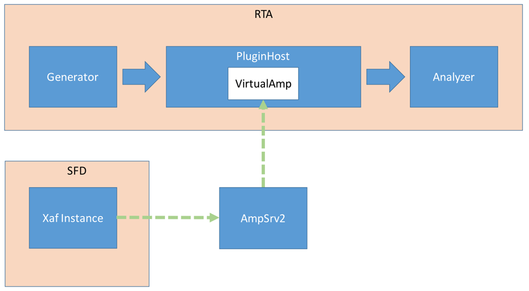
The Plugin Host is a host for virtual amp dll. The Plugin Host supports up to 3 instances of plugins (virtualAmp.dll in 64-bit), which are executed in series.
The block sizes and sample rate will be determined by the sound card settings and will be applied to all plugins. If the block size of the device/instance does not match the plugin’s block size, the plugin needs to internally handle the block size conversion.
The Virtual Amp does not support sample rate conversion in the current version. If a sample rate conversion is attempted, an error message will be displayed, and the processing will be stopped.
Steps to Configure Plugin Host
- Navigate to the IVP RTA tab and select Advanced from the ribbon bar. This opens the RTA Settings dialogue box.
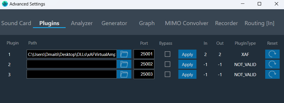
- On the RTA Settings dialogue box, select the Plugins tab.
- Click on the folder icon to browse the xAF library path.
- Set the port number under the Port box.
- Enable the Bypass option (optional), if you prefer the input to be passed directly to the next plugin or output without undergoing any processing.
- Click on Apply. The number of inputs, number of outputs, and plugin type will be automatically updated based on the provided signal flow. Similarly, you can set the remaining plugins.
Click on Reset (optional), to set back all the values in a specific row to their default values.
- Go to the Routing [in] tab.
- Set the inputs for “Plugin Host” (such as Generator1 and Generator2). These inputs will determine the channels from the Plugin Host that will be used.
- Set inputs for “SoundOut” in order to route the PluginHost output channels to the sound card outputs.
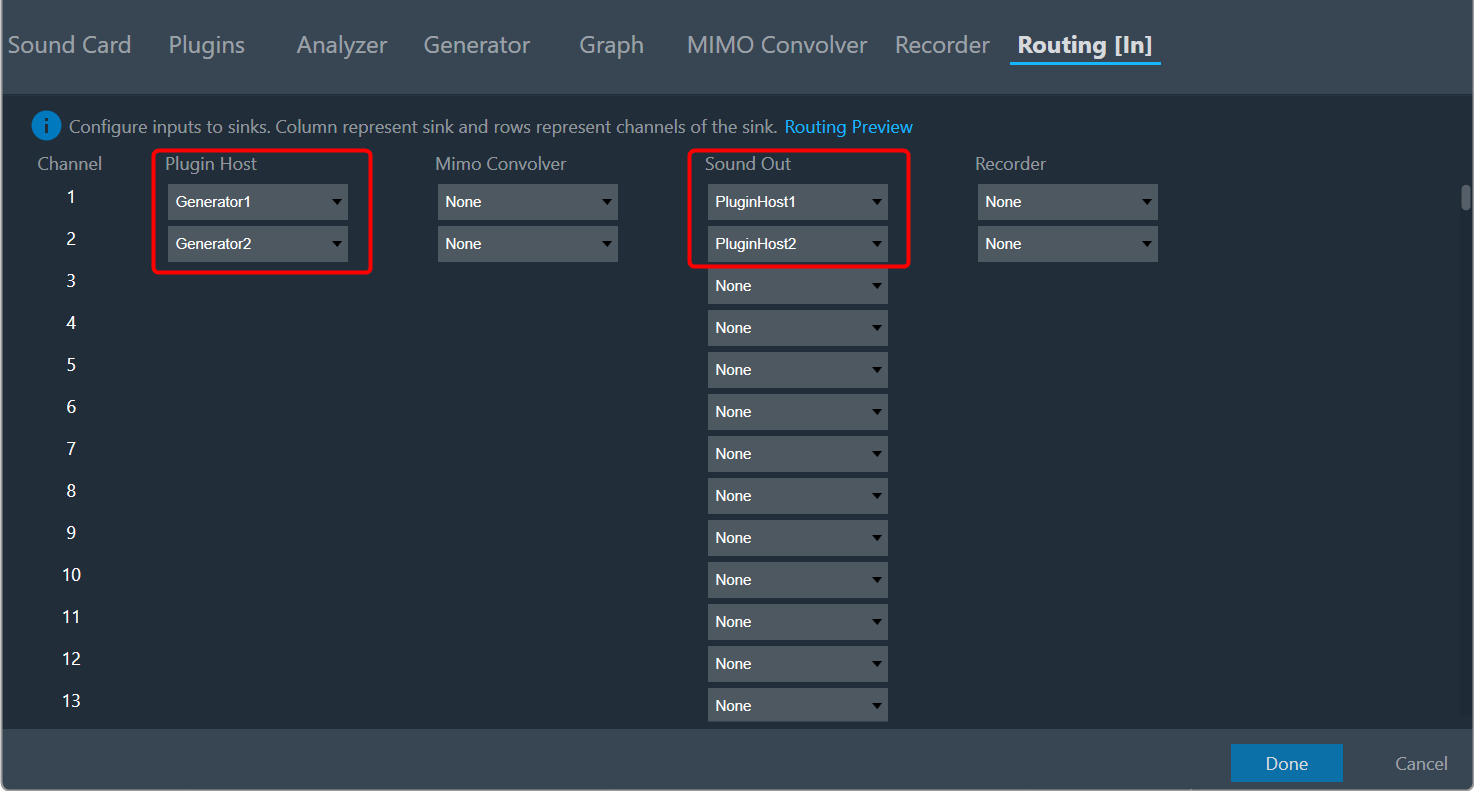
- If you want to display the output of PluginHost in RTA (optional), go to the Analyzer tab and select Plugin Host output as the channel source.
- Set the Channel source (such as Generator1, Generator2, PluginHost1, and PluginHost2) to display in the chart.
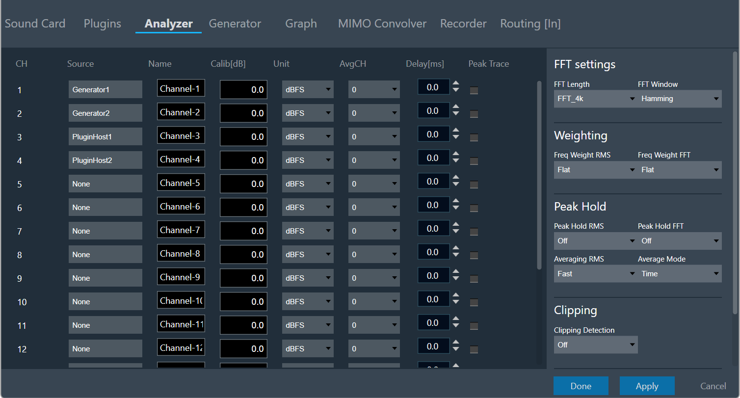
- Once the settings have been updated, click Done.
By default (no flash file available next to the virtualAmp.dll), the number of in-/outputs in the plugin host is -1.
The default Port Number starts from 25001.
Connect to the device through Plugin Host
-
Click Plugin Host.
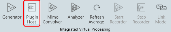
The Plugin host button is disabled until you select a valid plugin host.
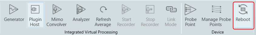
- Switch to the Signal Flow Designer window, configure signal flow, and click on Send Signal Flow. A pop-up message will ask you to reboot the device.
- Switch to the IVP RTA tab and click Reboot.
- Switch to the Device Designer tab and click on Connect Device to connect to the device.
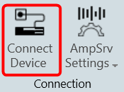
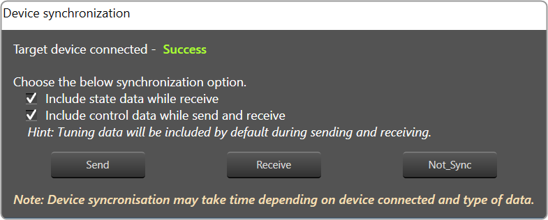
- A device synchronization dialogue box will appear, enable the desired synchronization option, and click Send.
If AmpSrv is unable to connect, close it and retry.
Now you can perform tuning on the IVP RTA.
-
Switch To the IVP RTA tab and click on the Generator and Analyzer option. In the graph section, the generated signal will be displayed.
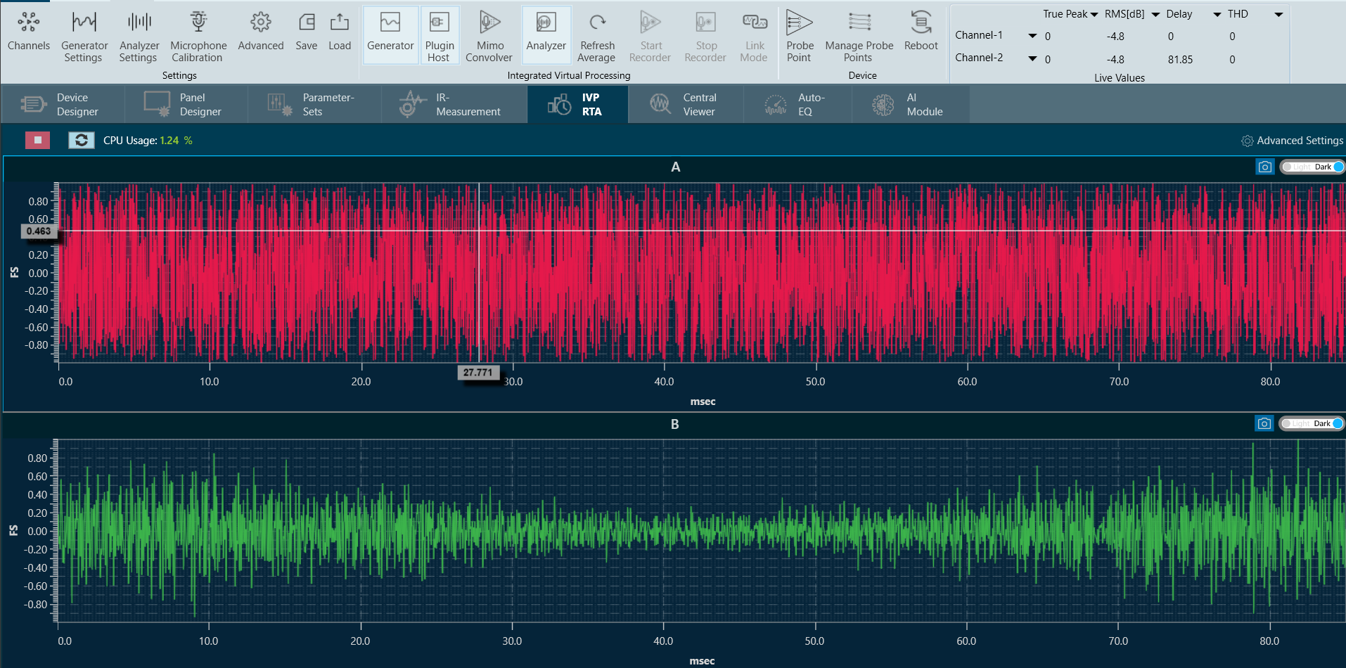
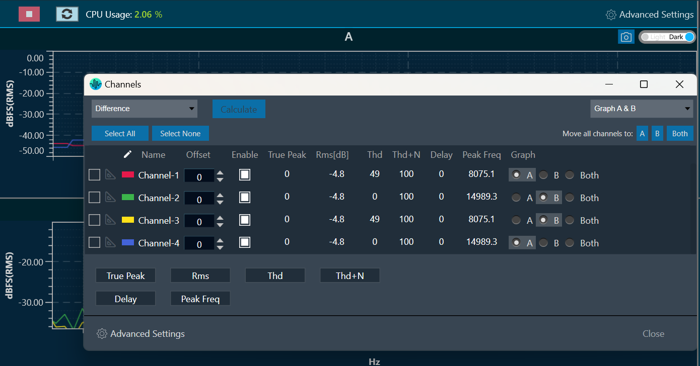
- Click on Channels to see the values of each channel. If you want to configure the graph, click on Advance Settings and go to the Graph setting.