The Power Manager Audio Object is intended to protect GreenEdge speakers from damage. Power Manager can limit peak-voltage and average-power delivered to speakers by usage of three limiters. The three limiters are grouped into two main sub-blocks. The peak-voltage sub-block consists of a frequency-dependent limiter which protects against cone over-excursion. The power-limiter sub-block is made up of a short-term and a long-term limiter, each of which can be configured to attack at a distinct power threshold over an independent time-averaging window. The limiters can be triggered separately. The data necessary for configuring voltage and power limiting is provided by the transducers team.
The power limiter is meant to protect the speaker’s components from overheating.
Use Case: Power Manager is intended for the protection of GreenEdge speakers. These are usually placed on “boosted” channels (with voltages above battery level), which increase the risk of damage.
Power Manager Properties
| Properties | Descriptions |
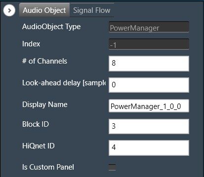
| # of channels | The number of channels are configurable.
|
| Display Name | Display the name of the PowerManager audio object in signal flow design. It can be changed based on the intended usage of the object. |
| Object mode | The Power Manager audio object does not support any mode. |
| Additional Configuration Parameters |
|
Additional Configuration Parameters
Look-ahead delay [samples]: The fixed delay in samples for the audio signal. This delay improves the response of the peak-voltage limiter at frequencies over 10 kHz.
Tuning Parameters
The power manager consists of the following parameters as tuning options in GTT for each channel.
From AWX “Y” release, these parameters are not saved to set files. These parameters need to be tuned manually, cannot be loaded from set files.
|
Name
|
Unit
|
Format
|
Range
|
Default
|
Description |
| StAvgPowerTime | s | Float | 0.1 – 100 | 2 | Averaging time window for the short-term power limiter. |
| LtAvgPowerTime | s | Float | 0.1 – 100 | 10 | Averaging time window for the long-term power limiter. |
| StPowerTrsh | W | Float | 0 – 100 | 10 | The power threshold over which the short-term power limiter will start reducing gain. |
| LtPowerTrsh | W | Float | 0 – 100 | 5 | The power threshold over which the long-term power limiter will start reducing gain. |
| PowerAttRate | dB/s | Float | 0 – 5 | 1 | The rate at which any of the power limiters will reduce gain when the threshold is crossed. |
| PowerRelRate | dB/s | Float | 0 – 5 | 1 | The rate at which any of the power limiters will go back to unity gain when the threshold is not being crossed. |
| PowerDepth | – | Float | 0 – 1 | 3.8E-07 | The maximum attenuation allowed for the power limiters. |
| VoltPeakTimeConstant | s | Float | 0 – 5 | 0.008 | The tau-constant for the first-order averaging filter used in envelope detection. The envelope level will decay at this rate when the signal peak is at a lower level. |
| VoltTreshLinearScale | V | Float | 0 – 100 | 1 | The reference threshold from which the contour filters bias the incoming signal. |
| VoltAttRate | dB/s | Float | 0 – 30000 | 2000 | The rate at which the peak limiter reduces gain when the contoured threshold has been crossed. |
| VoltRelRate | dB/s | Float | 0 – 30000 | 500 | The rate at which the peak limiter goes back to unity gain when the contoured threshold is not being crossed. |
| VoltageScalar | V | Float | 1 – 100 | 1 | The relation between the configured limiter-threshold voltage and the output voltage of the power IC used. |
In Addition to the above tuning parameters, Power Manager uses below filters to model the peak voltage and the admittance of the speaker.
- Voltage Contour Filters: Cascade of three bi-quadratic filters which are used to model the frequency-dependent peak-voltage limit for the speaker.
- Admittance Filters: Cascade of three bi-quadratic filters, which are used to model the admittance of the speaker. These are used to calculate current consumption and in turn estimate power.
Voltage contour filters and Admittance filters coefficients loaded into DSP/Amplifier can be visualized in SV tree and GTT panel.
|
Name
|
Unit
|
Format
|
Range
|
Default
|
| b0 | – | Float | -100 – 100 | 1 |
| b1 | – | Float | -100 – 100 | 0 |
| b2 | – | Float | -100 – 100 | 0 |
| a1 | – | Float | -100 – 100 | 0 |
| a2 | – | Float | -100 – 100 | 0 |
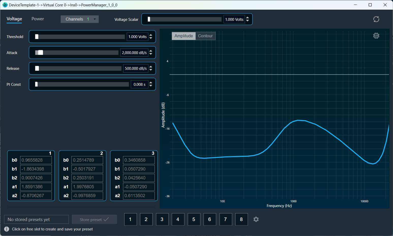
GTT panel also displays frequency response of filters. Please note that the filter coefficients cannot be tuned from GTT. The filter coefficients are loaded in DSP/Amplifier through a unique API.
- Voltage-Contour and Admittance Filter Coefficients Generation: The Transducer engineer provides specifications that include the recommended speaker peak voltages (used to design the voltage contour filters, which prevent over-excursion), impedance and power dissipation (used to design the admittance filters, which prevent overheating). The voltage contour and admittance filter coefficients need to be generated based on the aforementioned specifications using a curve-fitting tool, typically a MATLAB GUI.
The transducer specifications also include the recommended crossover filters. Make sure the crossovers are present and as close as possible to the specification to remove spectral content that could affect the power manager performance.
State Parameters
| Parameters | Description |
| Voltage contour filter coefficients | Used to read back voltage contour filter coefficients from the target DSP. |
| Admittance filter coefficients | Used to read back the admittance filter coefficients from the target DSP |
Control Interface
The PowerManager AO does not have any control inputs or control outputs.
Native Panel
PowerManager AO supports native panel. The native panel window has different controls for configuring tuning parameters, fields for displaying coefficients and graph for displaying output voltage/ power. Native panel can be opened by double-clicking on the PowerManager object in the SFD. For more details, refer Power Manager Panel.