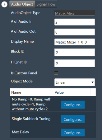
The Matrix Mixer audio object is used to calculate weighted output audio based on a combination of input audio. In addition to this, the object also supports delay of input channels.
Use Case: The Matrix Mixer takes in a configurable number of input and output channels. Each output of this object is a weighted sum of all the input channels. Any input can get summed into any output with or without a delay.
Matrix Mixer Properties
Below table describes about the Matrix Mixer audio object properties and functionality.
| Properties | Description |
| # of Audio In | Number of input channels.
|
| # of Audio Out | Number of output channels.
|
| Display Name | Display the name of the Matrix Mixer audio object in signal flow design. It can be changed based on the intended usage of the object. |
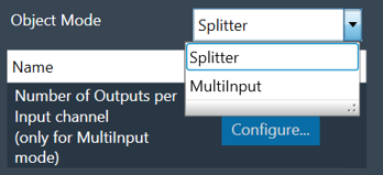
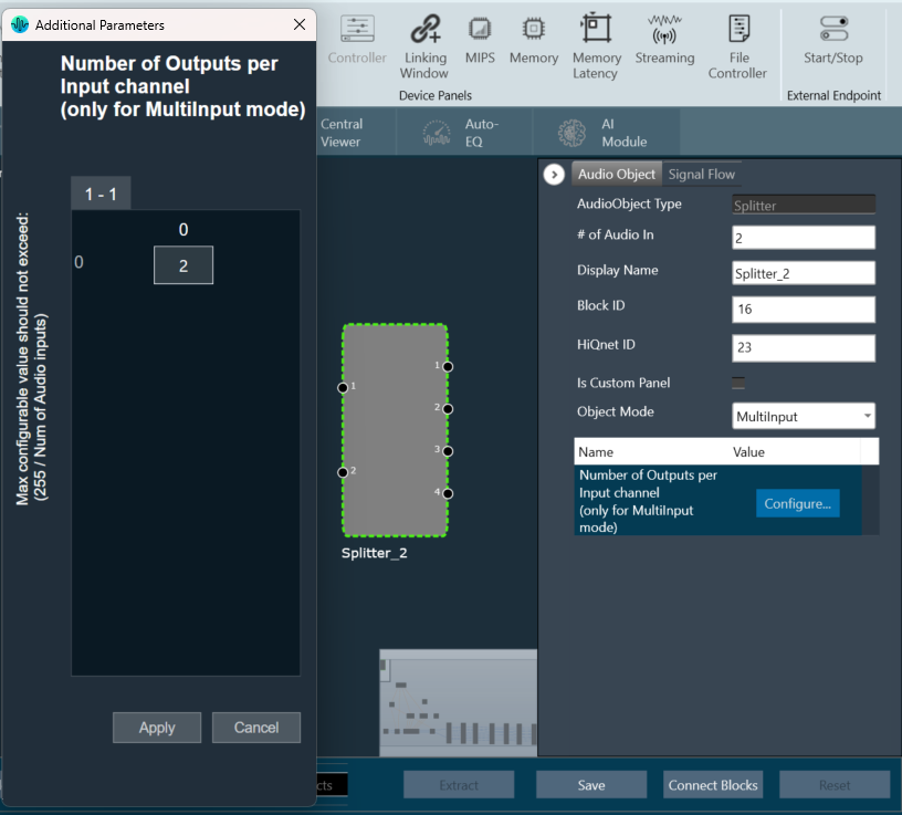
| Object Mode | Matrix Mixer object operates in one of the following two modes.
|
This object supports DelayMatrixMixer function.
Mode
The Matrix Mixer object supports two different modes of operation.
| Mode | Description |
| Linear (Default) | In this mode, the gain values (channel weights) are configurable on a linear scale in the range -10 to +10. |
| dB | In this mode, the gain values are configurable in decibels in the range between -128 dB to 20 dB and these decibel values are converted to linear values by xAF by the formula given below before multiplying with input channel samples.
|
Additional Parameters
The Matrix Mixer audio object can be configured with the following additional parameter:
| Parameter | Descriptions | |
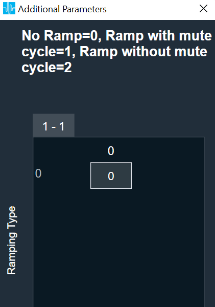
| No Ramp = 0,
Ramp with mute cycle = 1, Ramp without mute cycle = 2 |
The mixer also has three ramping types that can be configured through an additional number of parameters:
In the SFD, you can set the number of input and output channels. These channels do not need to be identical. The mode and ramping type are also configurable in the SFD. In the GTT, the Matrix Mixer exposes variables for tuning, for each input and output channel. You can modify these to change the weights used to scale the input channels. In the ramp modes, additional ramp time and control variables are exposed as explained above |
 |
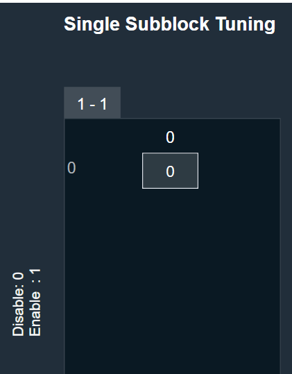
| Single Subblock Tuning | The object has an additional configuration variable “Single Subblock Tuning” to enable or disable it. On enabling it, allows contiguous memory allocation and the gain values can be tuned as single subblock.
By Default, Single Subblock Tuning is disabled. |
 |
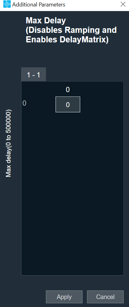
| Max Delay | The object has an additional configuration variable “Max Delay”.
Range: The value ranges from 0 to 500000 samples. By default, it is set to 0 samples. Ramp with mute cycle and Ramp without mute cycle types are not supported when Max delay is greater than 0. There is no native panel for DelayMatrixMixer |
 |
Tuning Parameters
The GTT can read or write into parameter memory using tuning command respectively. The memory stores a value per output channel that has a gain value to be multiplied by per input channel based on the mode. These parameters are tunable. Assuming the object is composed of NIn input channel and Nout output channels, the description will look as follows (depending on gain type).
For No Ramp mode
Parameter memory for “No Ramp” mode with Linear Gain
| Linear Gain | ||||||||
| Sub-block ID (Single Subblock tuning: Disabled) |
Sub-block ID (Single Subblock tuning: Enabled) |
Name | Type | Unit | Min | Max | Default | Description |
| 0 | 0 | float | -10 | 10 | 0 | NIn gain inputs for Ch0 output | ||
| 1 | 0 | NIn gain inputs for Ch1 output | ||||||
| … | 0 | … | ||||||
| Nout-1 | 0 | NIn gain inputs for ChNout-1 output | ||||||
Parameter memory for “No Ramp” mode with Logarithmic Gain
| Logarithmic Gain | ||||||||
| Sub-block ID (Single Subblock tuning: Disabled) |
Sub-block ID (Single Subblock tuning: Enabled) |
Name | Type | Unit | Min | Max | Default | Description |
| 0 | 0 | float | dB | -128 dB | 20 dB | -128 dB | NIn gain inputs for Ch0 output | |
| 1 | 0 | NIn gain inputs for Ch1 output | ||||||
| … | 0 | … | ||||||
| Nout-1 | 0 | NIn gain inputs for ChNout-1 output | ||||||
For Ramp with mute cycle mode
It has an additional ramp time configurable parameter.
Parameter memory for “Ramp with mute cycle” mode ramping with Linear Gain
| Linear Gain | ||||||||
| Sub-block ID (Single Subblock tuning: Disabled) |
Sub-block ID (Single Subblock tuning: Enabled) |
Name | Type | Unit | Min | Max | Default | Description |
| 0 | 0 | float | -10 | 10 | 0 | NIn gain inputs for Ch0 output | ||
| 1 | 0 | NIn gain inputs for Ch1 output | ||||||
| … | 0 | … | ||||||
| Nout-1 | 0 | NIn gain inputs for ChNout-1 output | ||||||
| Nout | 1 | Ramp Time | float | ms | 0 | 5000 | 500 | The time it takes for the ramp to complete. This value is split in half between muting and unmuting stages of the output signal. |
Parameter memory for “Ramp with mute cycle” mode ramping with Logarithmic Gain
| Logarithmic Gain | ||||||||
| Sub-block ID (Single Subblock tuning: Disabled) |
Sub-block ID (Single Subblock tuning: Enabled) |
Name | Type | Unit | Min | Max. | Default | Description |
| 0 | 0 | float | dB | -128 dB | 20 dB | -128 dB | NIn gain inputs for Ch0 output | |
| 1 | 0 | NIn gain inputs for Ch1 output | ||||||
| … | 0 | … | ||||||
| Nout-1 | 0 | NIn gain inputs for ChNout-1 output | ||||||
| Nout | 1 | Ramp Time | float | ms | 0 | 5000 | 500 | The time it takes for the ramp to complete. This value is split in half between muting and unmuting stages of the output signal. |
For “Rampwithout mute cycle” mode
It has an additional ramp characteristics parameters which are ramp down time, ramp up time, ramp down shape and ramp up shape.
Parameter memory for “Ramp without mute cycle” mode ramping with Linear Gain
| Linear Gain | ||||||||
| Sub-block ID (Single Subblock tuning: Disabled) |
Sub-block ID (Single Subblock tuning: Enabled) |
Name | Type | Unit | Min | Max | Default | Description |
| 0 | 0 | float | -10 | 10 | 0 | NIn gain inputs for Ch0 output | ||
| 1 | 0 | NIn gain inputs for Ch1 output | ||||||
| … | 0 | … | ||||||
| Nout-1 | 0 | NIn gain inputs for ChNout-1 output | ||||||
| Nout | 1 | Ramp down Time | float | ms | 0 | 5000 | 500 | The time it takes for the ramp to complete. |
| Nout | 1 | Ramp up time | float | ms | 0 | 5000 | 500 | The time it takes for the ramp to complete. |
| Nout | 1 | Ramp down shape | Int | 0 | 2 | 1 | Ramping shape, it can be jump (0), linear (1) and exponential (2). | |
| Nout | 1 | Ramp up shape | int | 0 | 2 | 1 | Ramping shape, it can be jump (0), linear (1) and exponential (2). | |
Parameter memory for “Ramp without mute cycle” mode ramping with Logarithmic Gain
| Logarithmic Gain | ||||||||
| Sub-block ID
(Single Subblock tuning: Disabled) |
Sub-block ID
(Single Subblock tuning: Enabled) |
Name | Type | Unit | Min | Max | Default | Description |
| 0 | 0 | float | dB | -128 dB | 20 dB | -128 dB | NIn gain inputs for Ch0 output | |
| 1 | 0 | NIn gain inputs for Ch1 output | ||||||
| … | 0 | … | ||||||
| Nout-1 | 0 | NIn gain inputs for ChNout-1 output | ||||||
| Nout | 1 | Ramp down time | float | ms | 0 | 5000 | 500 | The time it takes for the ramp to complete |
| Nout | 1 | Ramp up time | float | ms | 0 | 5000 | 500 | The time it takes for the ramp to complete |
| Nout | 1 | Ramp down shape | int | 0 | 2 | 1 | Ramping shape, it can be jump (0), linear (1) and exponential (2). | |
| Nout | 1 | Ramp up shape | int | 0 | 2 | 1 | Ramping shape, it can be jump (0), linear (1) and exponential (2). | |
DelayMatrixMixer
The object functions as DelayMatrixMixer with Delay Pool when the additional configuration variable “Max Delay “ is set to more than 0 samples. A “Delay” tuning parameter is added in addition to the gain parameter for each input channel. The delay buffer (of length Max Delay) is shared by all the channels. Therefore, the available delay for each channel depends on the delay values configured for the other channels. The input channels are multiplied with the channel weights and are applied with delay configured and summed at the output channel.
| Parameter | Description | Range | Default |
| Delay | Delay to be applied across each channel. | 0 to Max Delay(samples) | 0 |
| Gain | Gain to be applied across each channel | Linear: -10 to +10
dB: -128 dB to 20 dB |
Linear: 0
dB: -128 dB |
Control Interface
There are no control parameters available for Matrix Mixer audio object.