The purpose of Limiter audio object is to control the output level of the audio.
This AO supports in-place computation based on the core type.
Use Case: The Limiter AO can be used wherever there is a necessity to limit the signal level to be below a safe threshold level. A typical example is to protect speakers from unsafe signal levels.
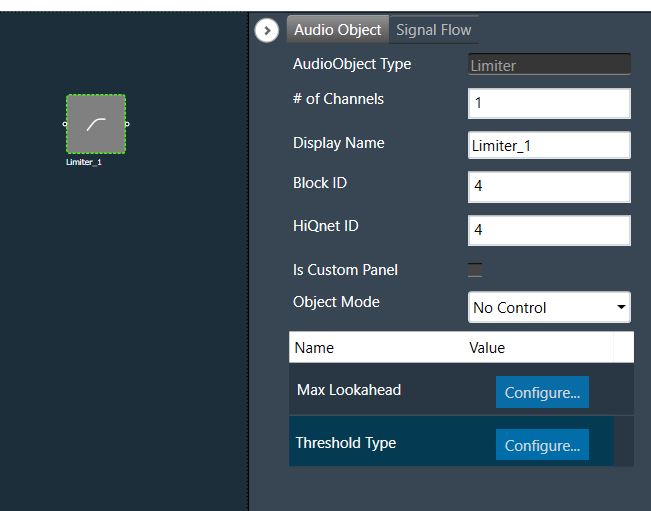
Limiter Properties
Below table describes about the Limiter audio object properties and functionality.
| Properties | Description |
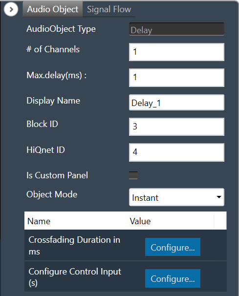
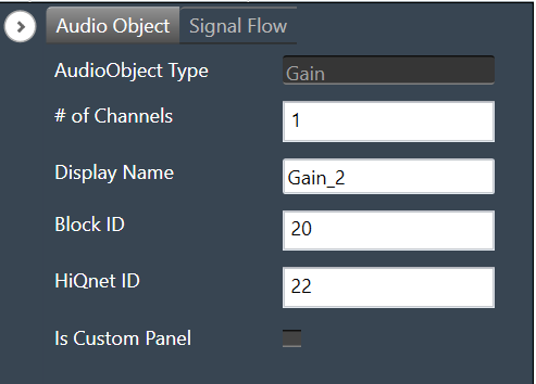
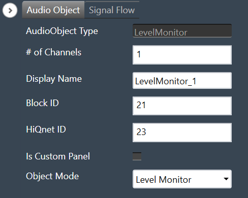
| # of Channels | The number of audio channels it can process is configurable in the SFD and each channel has its own set of specifications.
|
| Display Name | Display name of the Limiter audio object in signal flow design. It can be changed based on the intended usage of the object. |
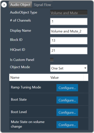
Mode
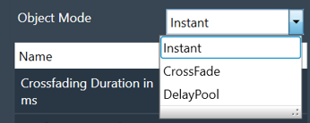
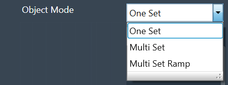
The Limiter audio object supports following three modes:
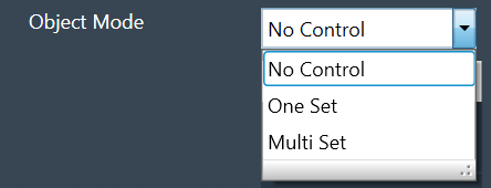
- No Control: No option for changing threshold value through control input. This is the default mode.
- One Set: One control input whose value is applied to change the threshold of all the channels
- Multi Set: Individual control input for each channel to change the threshold. If the number of channels exceeds 1, the control inputs are grouped as one block control input.
Additional Parameters
| Parameter | Description | |
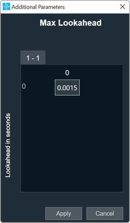
| Max Lookahead | Max Lookahead value is used to define the maximum lookahead time. During tuning from GTT, you can vary the lookahead time from 0 to the value set in the additional parameter.
The memory requirement largely depends on the lookahead time, and this feature helps you to define their optimal maximum lookahead time based on the memory availability. This can be configured during design time.
Size of the lookahead delay buffer (in float words) = round (sampleRate * Max Lookahead) For a sample rate of 48000 and maximum lookahead of 0.15 s, the required buffer size is 7200 float Words. Hence this variable is made configurable to enable the user to choose optimal maximum lookahead value based on the available memory. |
 |
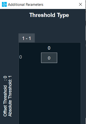
| Threshold Type | This additional variable is used only in One Set and Multi Set modes.
Under this modes, the AO will be having control input(s) and through this additional variable the user configures whether to use the control input value as absolute threshold or offset threshold. This option can be configured during design time.
The default value is 0. |
 |
Attack Phase
The Limiter operates in two modes during the attack phase when the input signal level is higher than the desired threshold.
- Fixed attenuation of 10 dB within the given attack time if the difference between the input signal level and the threshold is much higher. This phase is used initially to bring down the Limiter output quickly closer to the threshold.
- Adaptive attenuation if the threshold is slightly lower than the input signal level. This is deployed towards the end of attack phase for fine tuning the output level to match the threshold.
Hence if the threshold is less than the input signal by less than or equal to 10 dB, then within the given attack time the Limiter output is restricted to the threshold level ± 1 dB.
If the threshold is much lower than the input signal level (say 30 dB), the difference is first brought down to less than 20 dB within the attack time; the difference is further reduced to less than 10 dB within twice the attack time; finally, the output matches the threshold ± 5% within thrice the attack time.
Release Phase
The release time is the time taken by the Limiter output to follow the input signal level from the time the input signal level drops below the threshold. During this phase, the Limiter output follows exponential (time constant) growth to reach the input level.
Accordingly, the output level will be as given below during this phase (If the release time is denoted as R, and the difference between the output level at the start of release phase and the input signal level is P dB):
- After R sec: 63% of P dB
- After 2R sec: 86% of P dB
- After 3R sec: 95% of P dB
Tuning Parameters
The tuning parameters are limited to safe range such that Limiter audio object shall not produces NaNs. In GTT, the limiter exposes the following parameters for each channel of the limiter:
| Parameters | Description | Type | Range | Default |
| Gain | Controls the upper bound of gain that the limiter applies on weak signals. | Float | 0 to 30 | 0 dB |
| Threshold | Controls where the limiter begins to activate. | Float | -30 to 0 | 0 dB |
| Attack Time | Controls the limiter’s attack time for each channel. | Float | 0.1 to 20 | 1 ms |
| Release Time | Controls the limiter’s release/hold time for each channel. | Float | 1 to 2000 | 150 ms |
| Hold Time | Controls the hold counter. | Float | 0 to 10 | 10 ms |
| Hold Threshold | Controls where the limiter enters hold or release. | Float | -1 to 0 | 0 dB |
| Look Ahead Time | Look Ahead buffer for controlling the overshoots. | Float | 0 to Max Lookahead | 0.0015 s |
| Bypass | Flag to bypass the Limiter operation for the particular channel. | Unsigned Long | 0 to 1
0 – Bypass Disable 1 – Bypass Enable |
0 |
State Parameters
| Parameters | Description | Type | Unit | Range | Default |
| Attenuation | The attenuation value for each channel indicates the amount of the gain reduction (attenuation) applied when the Limiter is active.
This value will not be updated while the limiter is in the ‘Bypass’ state. |
Float | dB | 0 to 60 | 0 dB |
| Effective Threshold |
Indicates the actual threshold value applied – for each channel. | Float | dB | -60 to 0 | 0 dB |
When the control input of the Limiter AO is configured as Absolute Threshold, the last applied setting will be used internally, which means the tuning parameter change will overwrite the control input and vice versa.
Control Interface
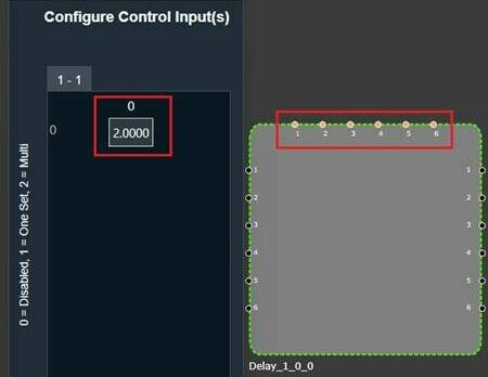
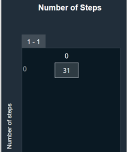
The Control audio object does not have any control output in any modes. However, the AO has control input(s) in One Set and Multi Set modes.
- In One Set mode, the object has one control input whose value is applicable for all channels.
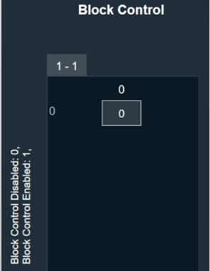
- In Multi Set mode, the number of control inputs is same as the number of channels – each channel having a dedicated control input. These control inputs in Multi Set mode are grouped as one Block Control input when the number of control inputs exceeds 1.
For further info on the Limiter audio object and its functional behaviour, please also refer to Limiter User Guide Supplement.