Known Issues with a workaround and will not be fixed
| Known Issues | Description |
| GTT Core Linking | AWXNG-5049: [SMART] Label names are lost when it’s associated AO (state variable) is removed from signal flow.
The linking that is done before extract will not be available on CAO edit as we are using a dummy device/core hence the hiqnetaddress would differ. Workaround: Do the smart window mapping only on CAO edit. |
| GTT Signal Flow | Volvo project getting a compiler error “Block ID range error with SpeakerProtection AO” (Block id for SpeakerProtection AO need not be 16 bit and hence need to be corrected at project end) |
Known Issues and will be fixed in next release
| Known Issues | Description |
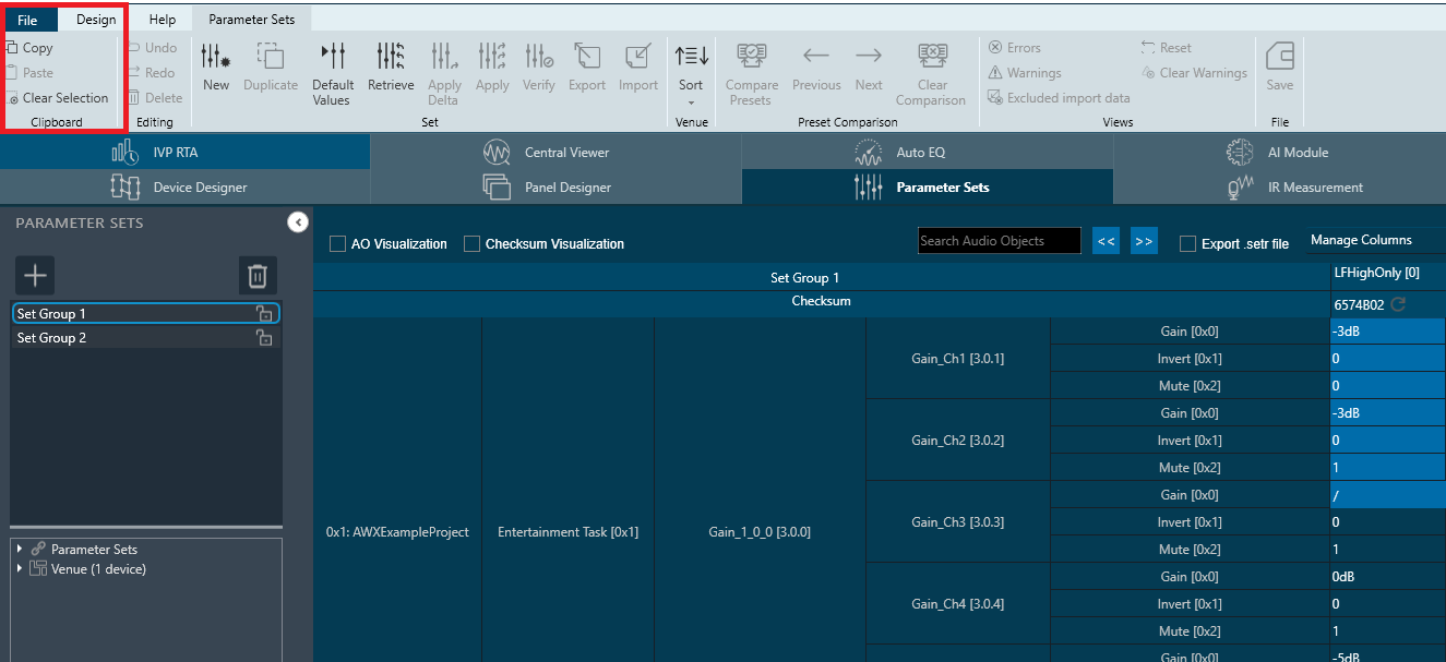
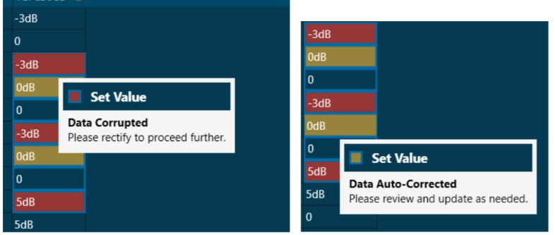
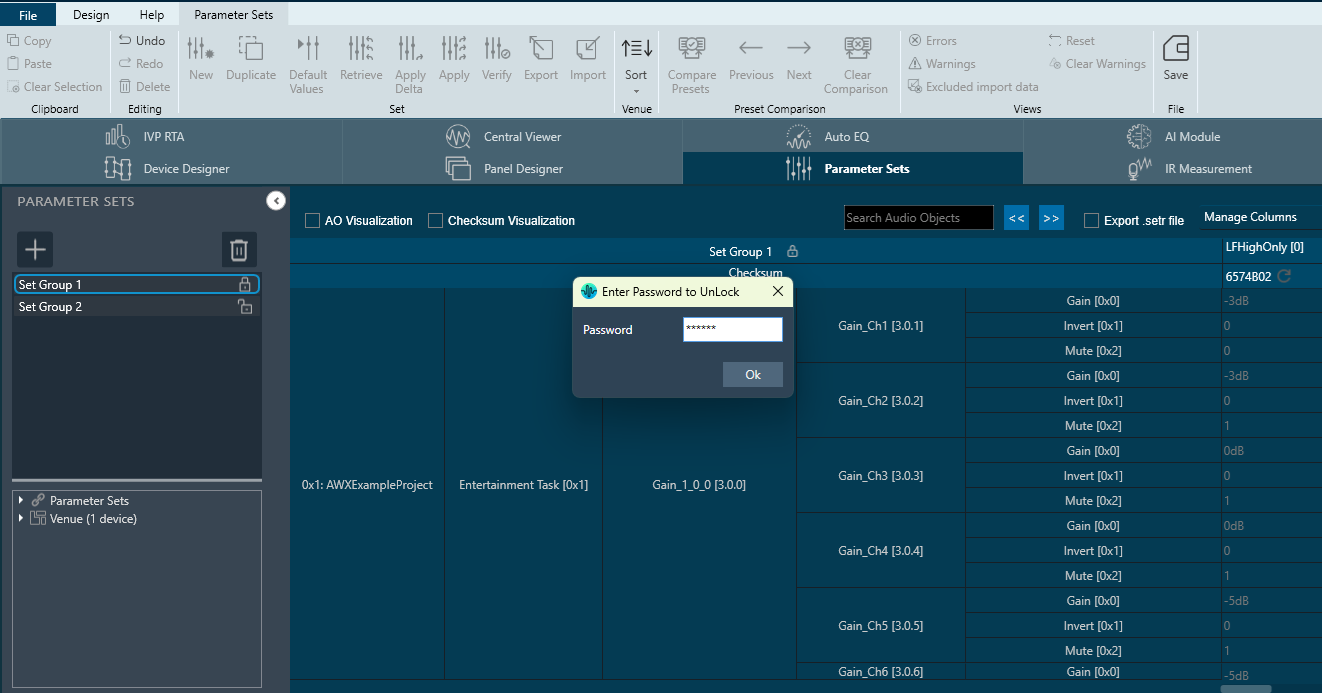
| Checksum | In read cases checksums Match When tuning data set is very small. |
| Probe points |
|
| UI/UX | Opens multiple windows during 1st time launch. |
| GTT MPC | Keeping the Map file open in Hex Editor Neo and try to export all from MPC (such that it tries to overwrite the map file which is open in Neo editor) results in GTT crashes. |
| GTT Core /SFD |
|
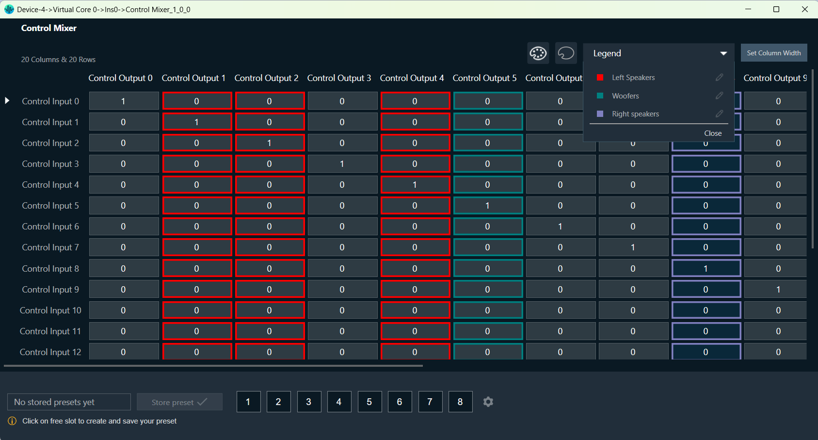
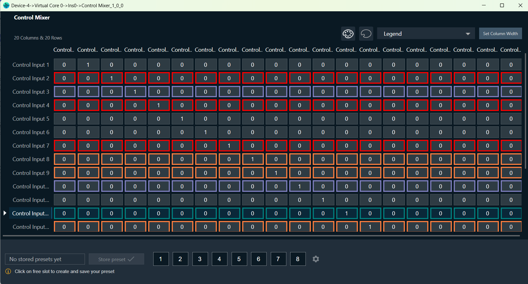
| GTT Native Panel | Legend View of Control Mixer Panel is not updated properly when we re-assign color and label.
Workaround: Reopen the panel, all labels will be visible in the Legend View. |
| Panel Designer | Help links are mapped incorrectly in some Custom Panel Windows. |
| MIPS Window | MIPS window is limited to 255 audio objects per core. |
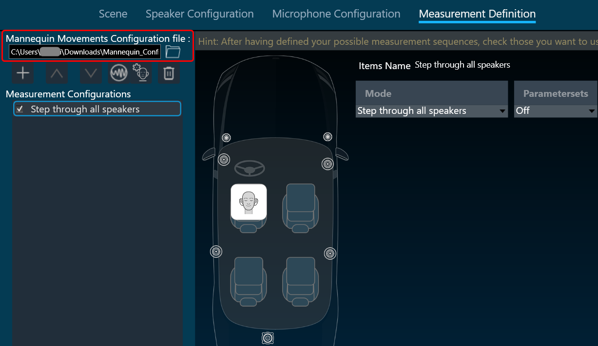
| RTA/IVP | RTA – Delay Mode do not show aligned values in Live ribbon bar vs Graph. |