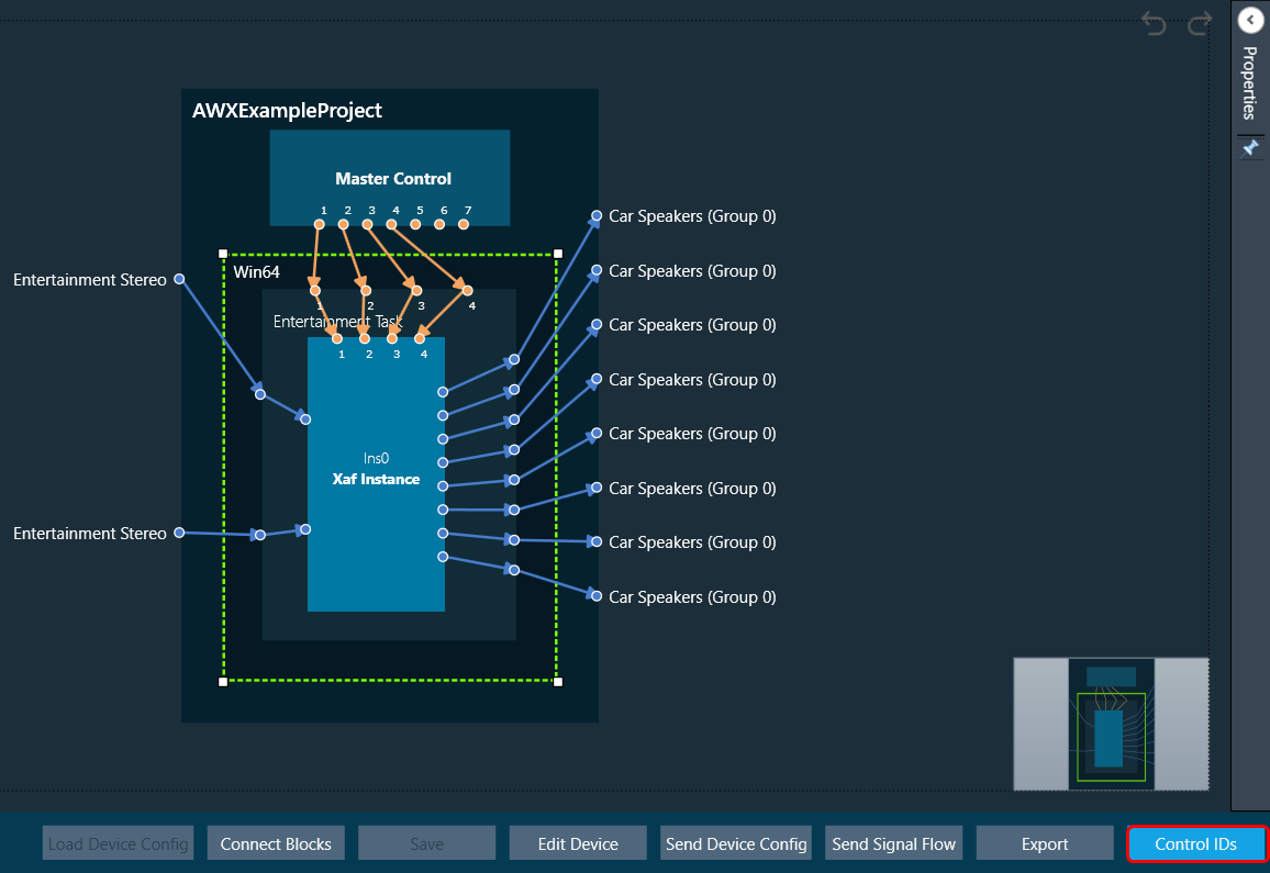
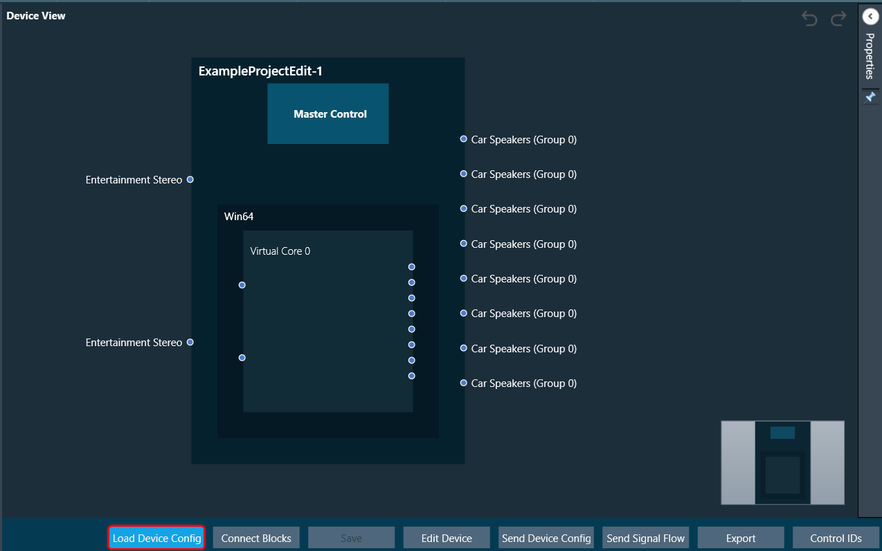
This section explains the device operation features available at the bottom of the Device Designer workspace.

Load Device Config
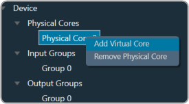
When there are no core objects in the cores, the Load Device Config option is enabled. The Physical Cores and Virtual Cores (available within a Physical Core) as well as their connection points that were fetched from the target during device discovery are visible after the device has been loaded. Since they are read from the device, the number of virtual cores and their connection points cannot be changed.
You can connect core objects by dragging them onto the virtual cores. Alternatively, you can select the “Load Device Config” option, which will read the target’s device routing information as well as the layout and routing between core objects and display it on the GUI.
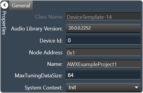
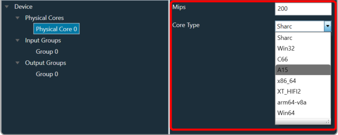
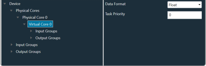
In the device view, a property section has been added to display and change the properties of chosen Core or Core Objects. When the virtual core or core object is selected, their respective properties are shown on the screen.
If you don’t clear the device view first, you won’t be able to save or access SFD.
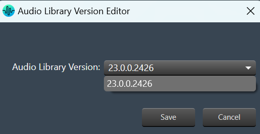
The device identification feature is enabled for audio libraries version 13 and higher.
Connect Blocks
You can auto-connect selected devices, cores, and core objects using Connect Blocks.
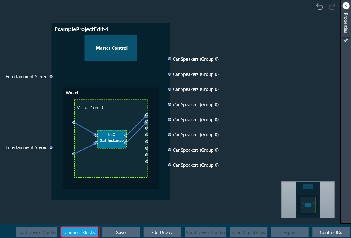
Choose at least two cores and click Connect Blocks.
You can auto-connect the following components.
- Device – Virtual Core(s)
- Virtual Core(s) – Virtual Core(s)
- Virtual Core – Core Objects (within selected Virtual Core)
- Core Object(s) (within same Virtual Core)
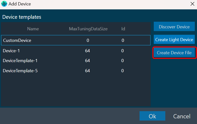
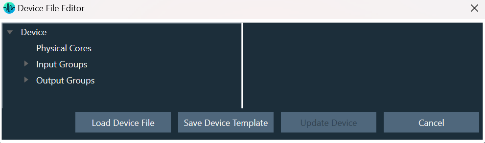
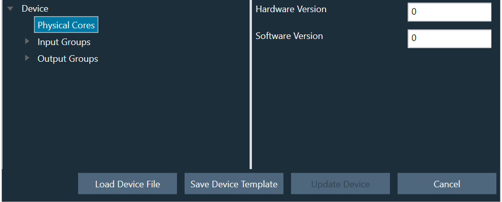
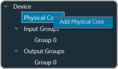
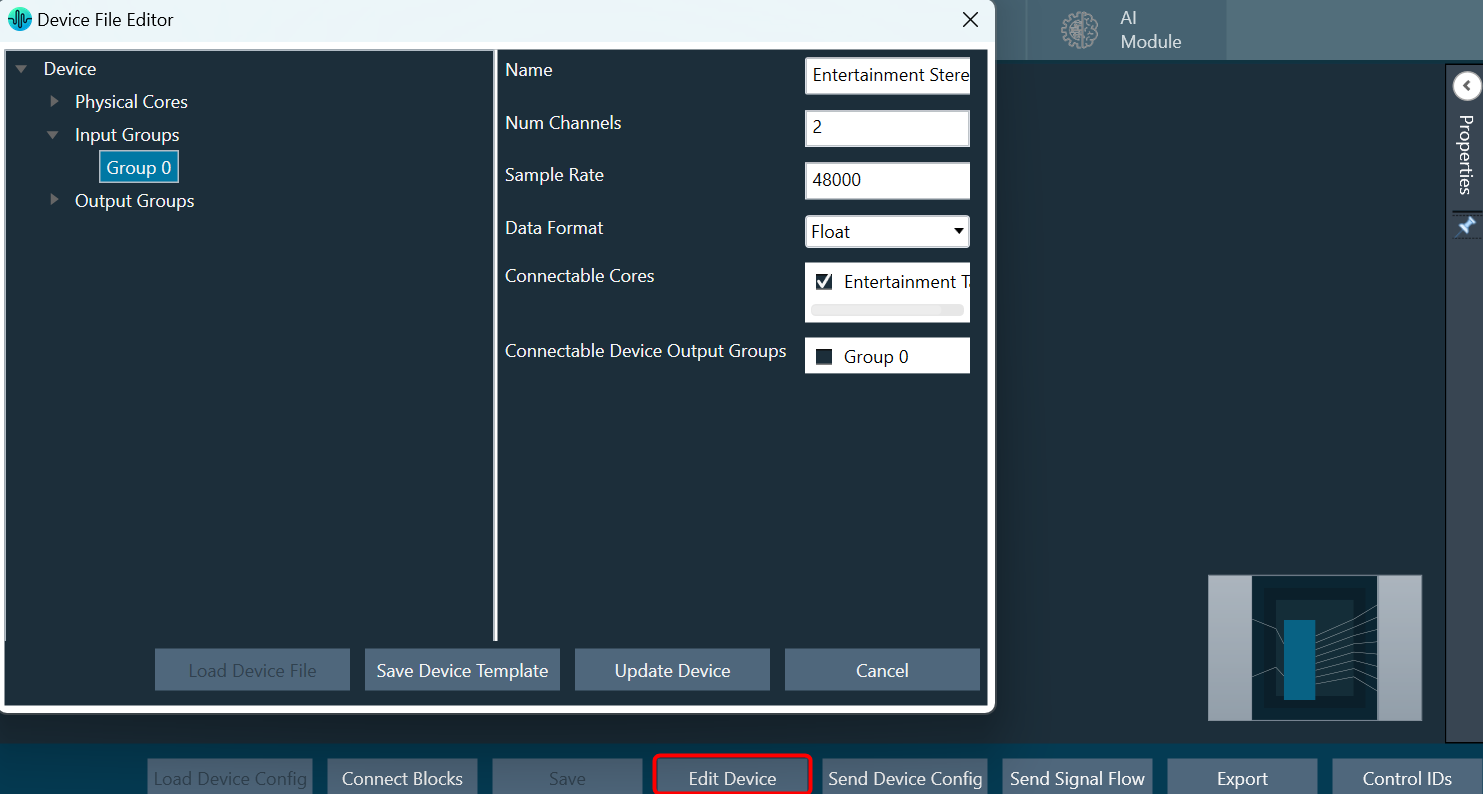
Edit Device
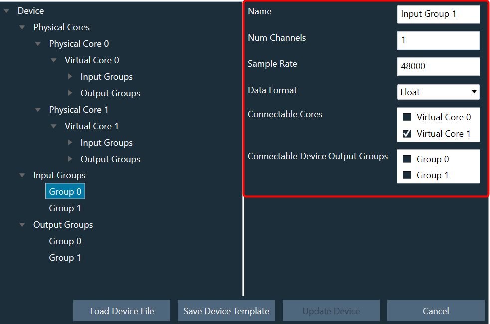
In Device File Editor you can modify the device configuration, then perform “Save Device Template” or “Update Device” operation.
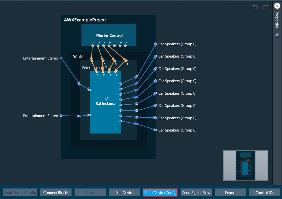
Send Device Config
You can create your own configuration and write this configuration to the target device. The Send Device Config option sends the device configuration (Core Objects, Device Routing, and Virtual Core routing) to the target device.
Before sending the device configuration, all the input and output connection points of the core objects must be connected. If any of the pins are not connected, an error message is displayed.
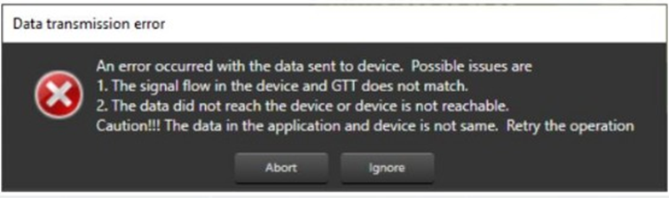
The Device view (number of Cores, Physical Cores, Connection points, Sample Rate, and Block Length) inside GTT and the data inside the Device. The flash file on the target should match before Sending the Device configuration. If the data doesn’t match, then the below transmission error is seen
The data in the device view (number of cores, physical cores, connection points, sample rate, and block length) and the data in the device. The flash file on the target device should match before the device configuration is sent. If the data doesn’t match, you will see the transmission error.
If any changes are made to the configuration, the send device config must be completed before sending the signal flow.
The device identification feature is enabled for audio libraries version 13 and higher.
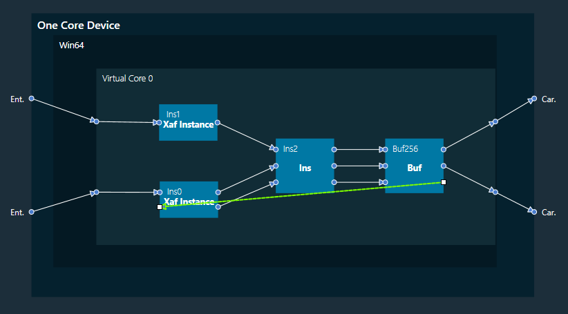
Feedback Loop
In the device view, feedback connections are allowed. You can connect the output of any core object as input to any other core object.
Core object Id defines the order of execution of core objects. Execution order of any core object depends on the IO dependency. IO side dependency is not considered when there are feedback loops.
Self-loop is not supported as feedback.
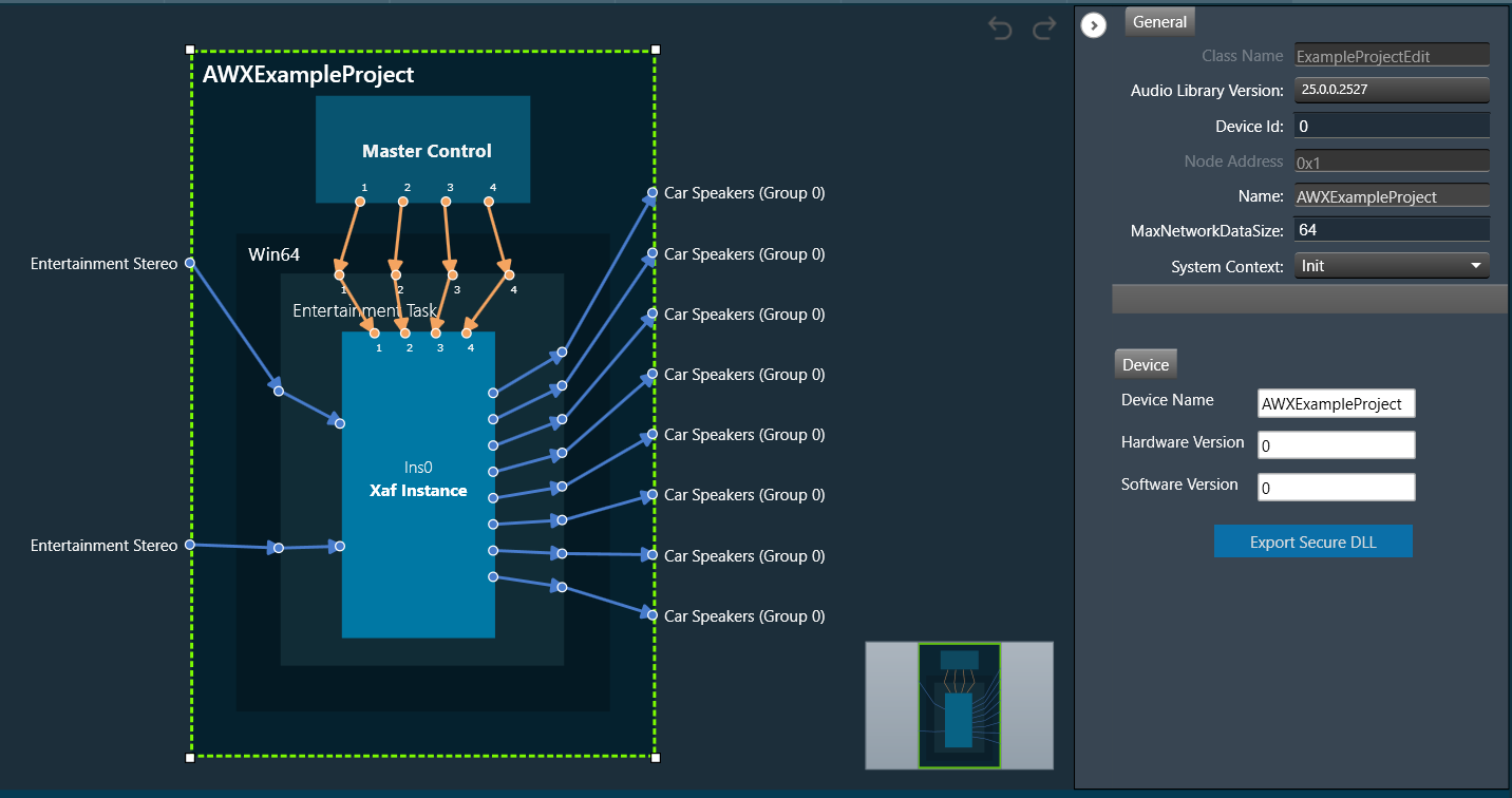
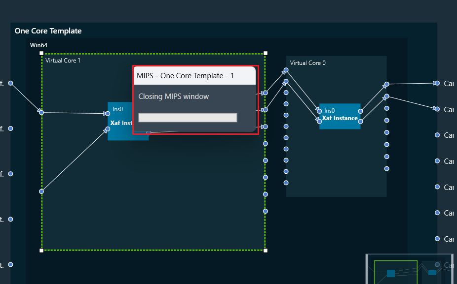
In the image, connection highlighted in green color is a feedback connection.
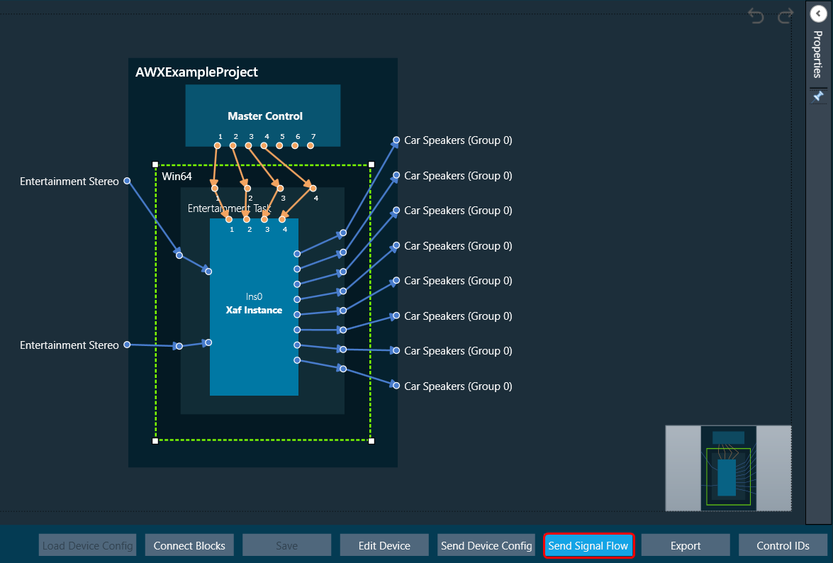
Send Signal Flow
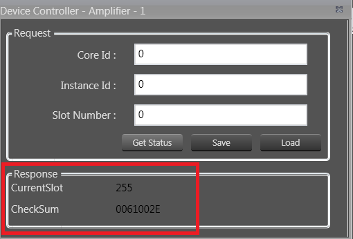
The Send Signal Flow option sends the configuration of the signal flow design to the target device. You can also use this to test how the target device responds to specific test signals. In a test scenario, you can configure specific test signals and send them to the amplifier.
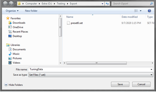
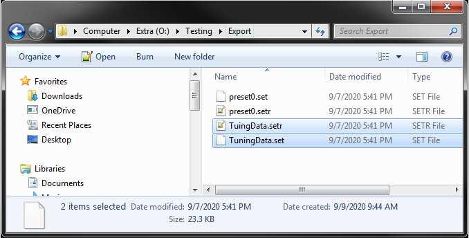
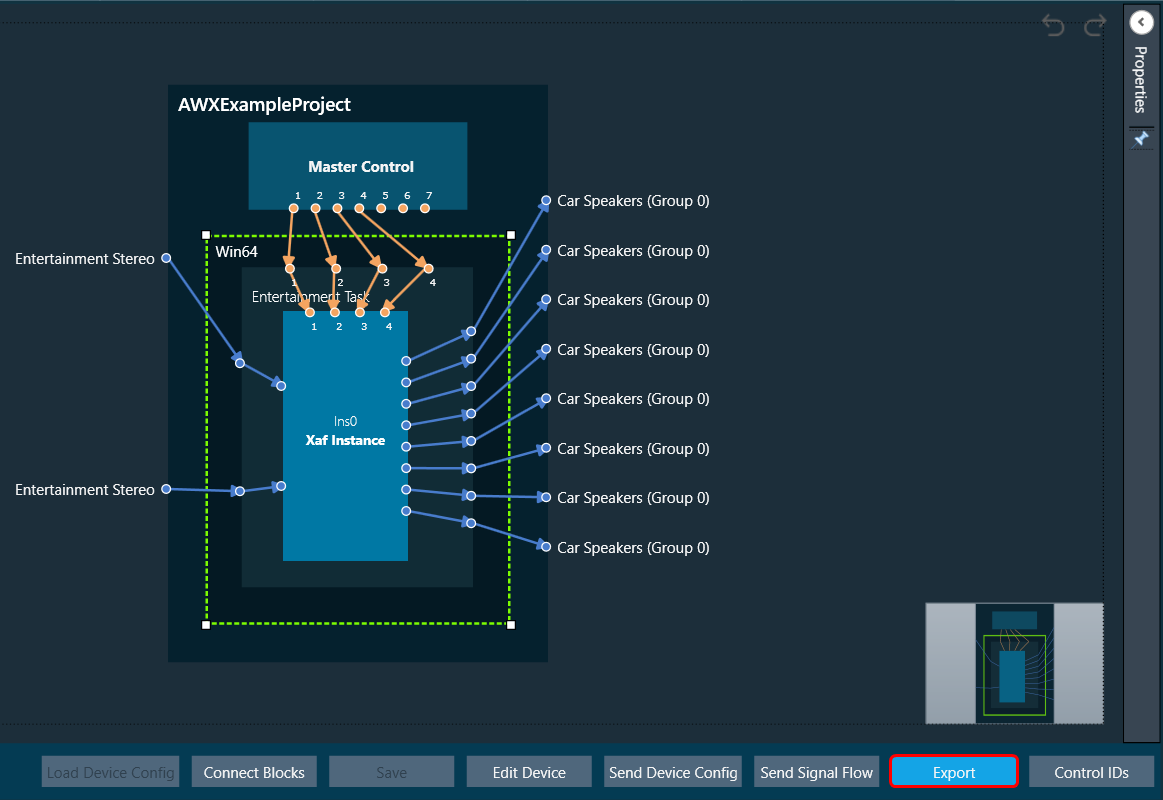
Export
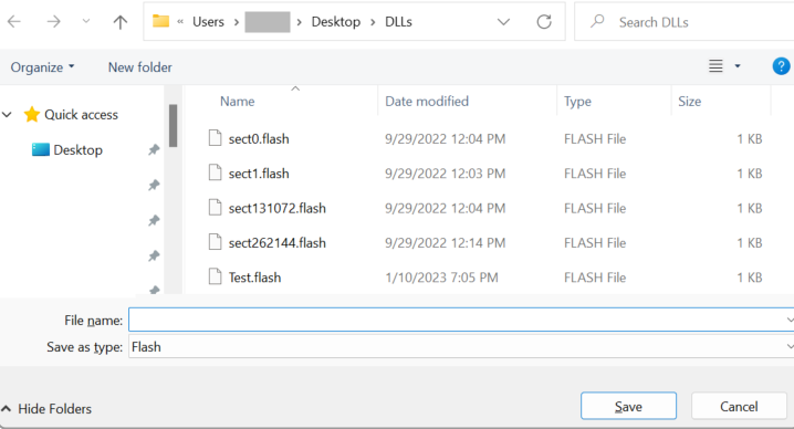
Using the Export option in the device view, you can export the device configuration data and the signal flow design details.
*.Core files would be created for each Virtual Core available in the device. One *.route file will be created for Device routing data. One .mcd file will be generated for master control data and one .SFD file will be generated per instance per core.
- One core file per virtual core in the signal flow.
- The core objects within the virtual core.
- The routing within those objects.
- The destination of the output pins of the virtual core.
- One signal flow file per xAF instance.
- This is the same legacy file.
- One input device routing file.
- This basically describes how the device input buffers are connected to the virtual cores and/or the device outputs.
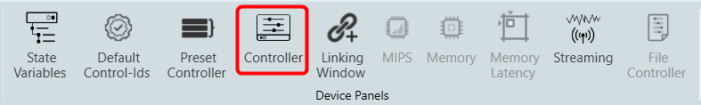
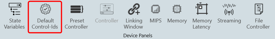
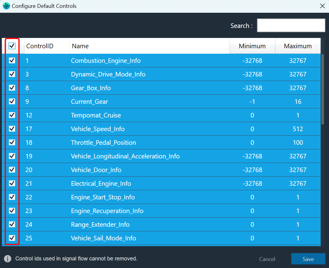
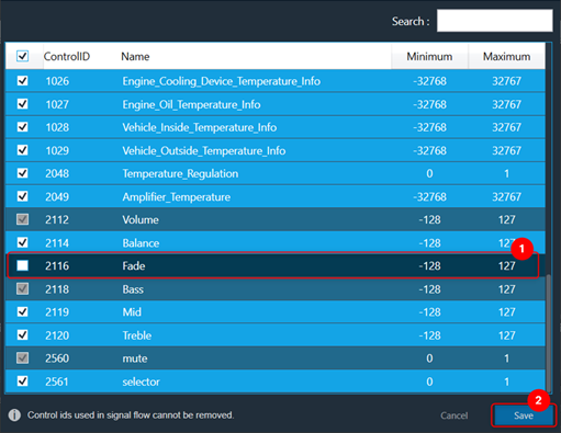
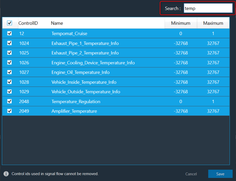
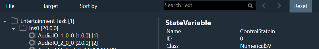
Control IDs
The Control IDs are used to configure Custom Control IDs. You can add, edit, export, and import Custom Control IDs data. For more details, refer to