The AudioworX Signal Flow Designer (SFD) allows you to deploy features across DSPs, SoCs, and ECUs. Harman and third-party technologies are available for drag-and-drop audio flow construction using a library of standard audio building blocks.
This audio processing can be simulated on a PC or target hardware while computing and memory measurements for each block are collected.
Follow the steps below to create a signal flow design:
- Double-click on the xAF instance in Device View to open the Signal Flow designer.
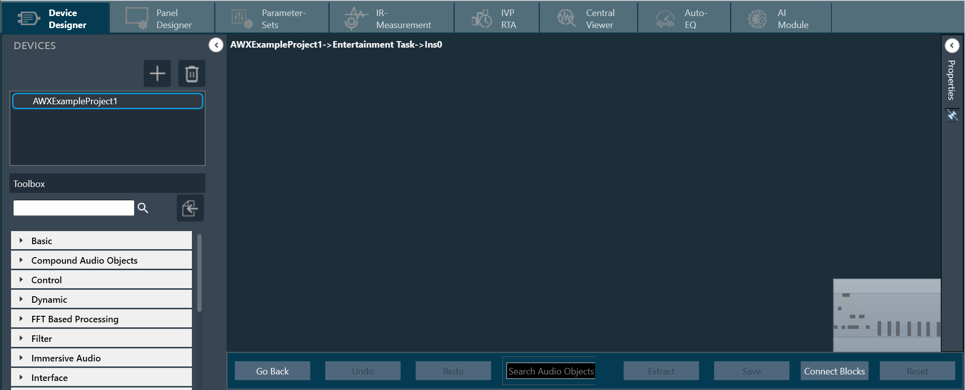
- Go to the Toolbox section, expand Interface, and drag the AudioIO audio object to the Signal Flow view. Similarly, add another AudioIO audio object to the Signal Flow view.
– When adding an xAF instance to a discovered device, this AudioIO can be added. Thus, this step is only necessary if these two AudioIO objects are absent.
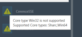
– The toolbox will filter audio objects based on the core type of the physical core where this Framework instance is added. The audio object will be marked with an exclamation mark to indicate that it cannot be used for building signal flow. You can hover over it to see which core types are supported.
- Select one of the AudioIO audio object and set the Object Mode parameter to Audio In. Similarly, select another AudioIO audio object and set the Object Mode parameter to Audio Out.
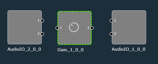
- Expand Basic and drag Gain audio object to the Signal Flow view. You can use any of the audio objects, for example Gain audio object is used.
Try to keep the Gain audio object between two AudioIO audio objects, or else you cannot connect the input or output pin with the Gain audio object.
Now, you can modify the audio object properties as per your requirement.
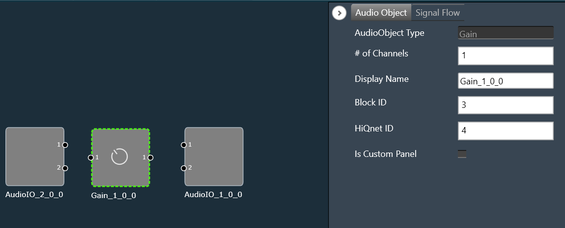
- Select the Gain audio object and set the # of channels parameter to 2. The number of channels determines how many connectors the AO will be allotted. You can assign as many channels as you want to your device in GTT.
- Hold the CTRL key, select all the audio objects from the Signal Flow view, and click Connect Blocks to connect all the audio objects. Or you can drag a connection from the output pin of an AO and drop to the input pin of another AO
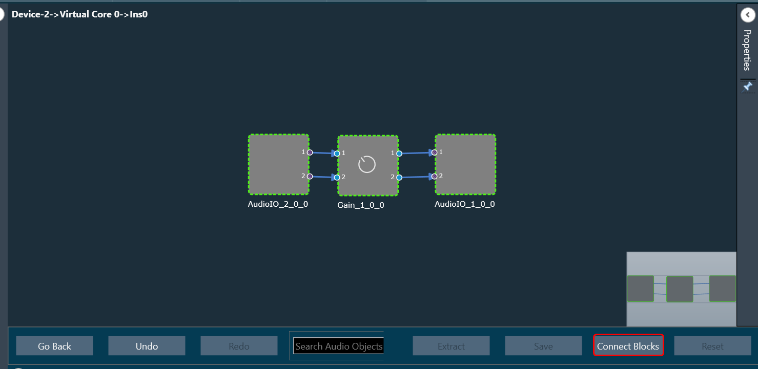
Now you have an input and output object, as well as an object to tune gain, invert, and mute parameters for each channel of the signal flow designer. - Click Save to save the signal flow design and click Go Back.
- Launch IVP and click on Send Signal Flow in device view.
A message “Signal flow successfully submitted” will be displayed. The Signal Flow is sent to the virtual amplifier.
Messages While Saving Signal Flow Design
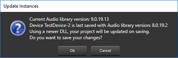
- If there is a version mismatch between the current audio library version and the version data on the device, a warning message appears asking whether to continue or stop saving.
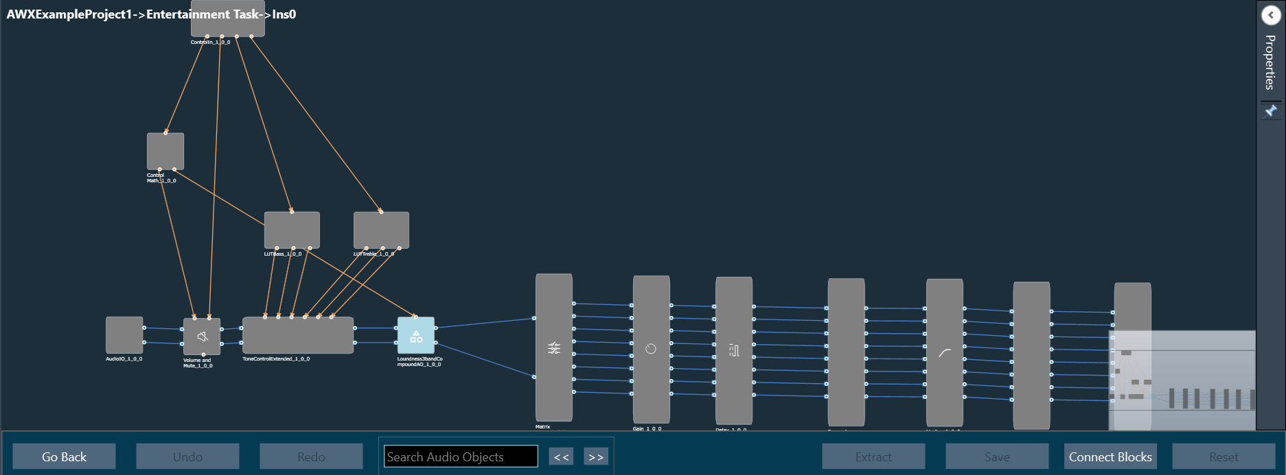
- If there is a tuning version mismatch between audio objects in the signal flow and audio objects in the toolbox, a warning message will be displayed, showing the tuning version differences, and those audio objects are highlighted in blue. Right-click on the particular AO and click on Upgrade Audio Object to resolve these errors or warnings.
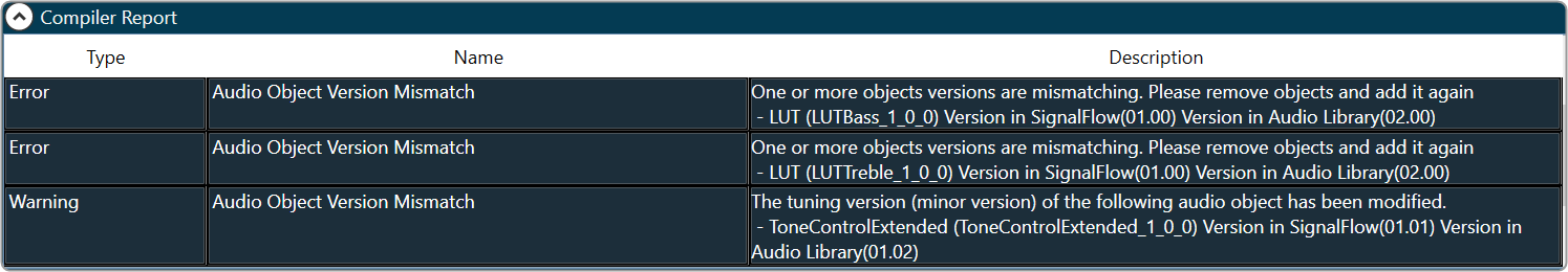
- If the existing audio object in the signal flow does not match the block length, sample rate, or core type, a compiler error will be displayed at the bottom of the signal flow window.

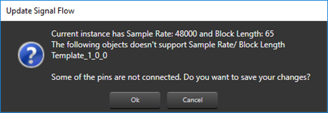
- If the Sample Rate/Block Length does not match, a message will be displayed asking if you want to continue or stop saving.
For more details about Signal Flow Design, refer to the Signal Flow Design user guide.