This section provides detailed instructions on configuring device panel features. Below are the topics covered under the section.
Related Topics
This section provides detailed instructions on configuring device panel features. Below are the topics covered under the section.
Related Topics
The Help tab provides quick access to information on AudioworX which include GTT and other modules, as well as detailed descriptions of its features and functionalities.
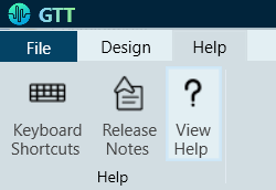
Clicking on any of the options within the Help tab will redirect you to a dedicated documentation page that provides detailed information on the selected topic.
When GTT project is open, press the F1 key on your keyboard to open AudioworX documentation page.
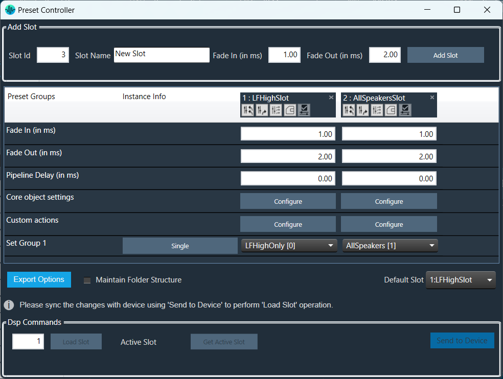
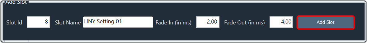
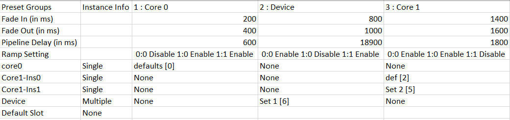
Steps to configure preset controller slot:
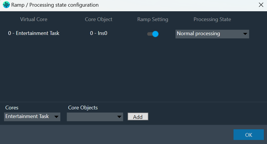
Ramp Settings configuration is supported from S+2 device library version.
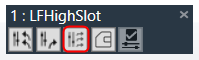
Slot Options
Retrieve Slot: The Retrieve Slot option in the generic sets window reads the state variable values of all the sets in a slot and updates them in the in the corresponding sets of Parameter Sets. Retrieve Slot button is available in the header of each slot.
Apply Delta Slot: The Apply Delta Slot feature only send tuning parameter present in the selected slot which are differing for the State variable tree. The tuning values of the presets are send to the device via XTP Tuning write messages. Apply Delta Slot option is available in the header of each slot.
Apply All Slot:The Apply All Slot feature sends all tuning values of the parameter irrespective of modified or not in the slot. The tuning values of the presets are send to the device via XTP Tuning write messages. Apply All Slot option is available in the header of each slot.
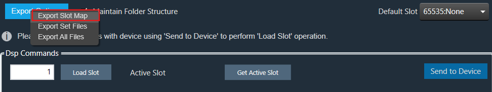
Export Slot: Once you have created a Set Map, click on the “Export Slot” option, and browse the desired path.
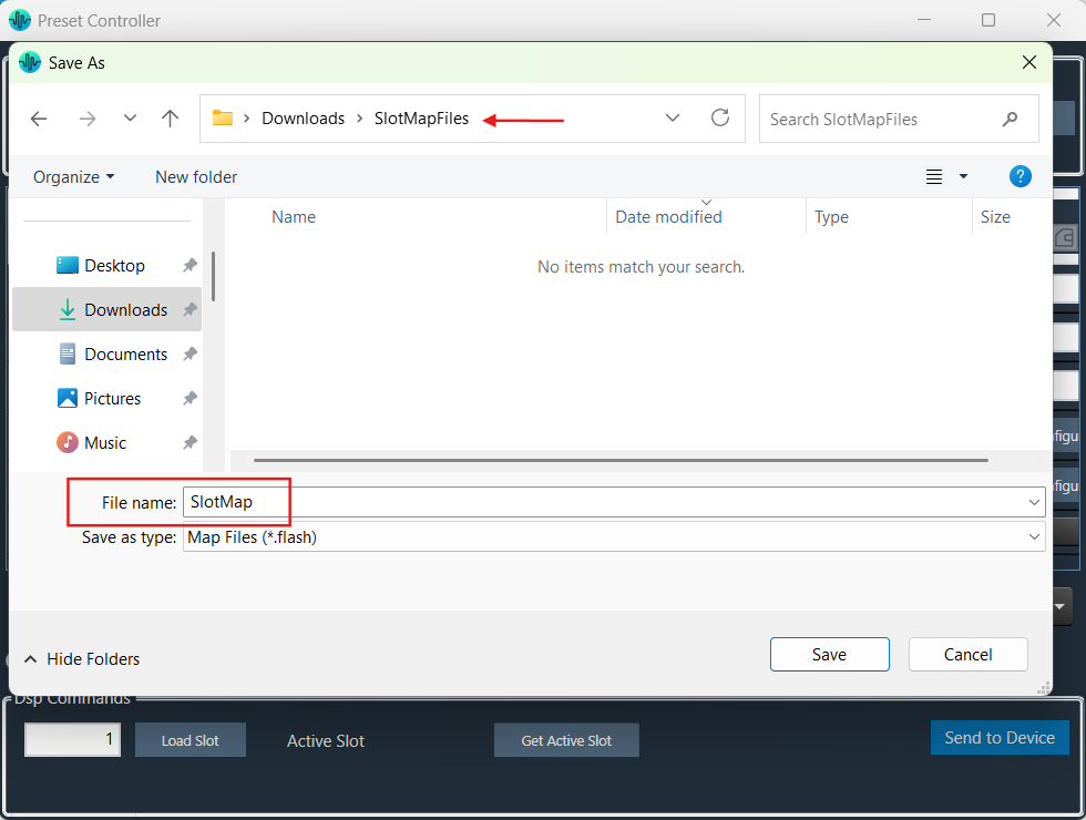
Flash file created in binary format. For virtual devices, use the file name as “sect262144.flash”.
Generic sets are persisted in the database, just like any other data in GTT.
Generic sets are also persisted in the .gttd file when the project is exported, and the same is available after importing. The selection of the default slots is dynamic and will not be persisted.
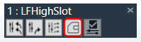
Verify Slot: This functionality is designed to compare the presets loaded on a device with those available in the GTT in order to ensure their accuracy.
This feature is available only in online mode. i.e. only when the device is connected.
To verify preset values, select a slot and then click the ‘Verify slot’ option. A read command is sent to the device for each state variable within of all presets under a slot. Once the value has been read, it will be compared with the corresponding value in the preset. If all values match, the verification process is considered successful. However, if any values do not match, an error message will be displayed, and an error report will be generated.
Sample error report is as attached here Set 1[2].
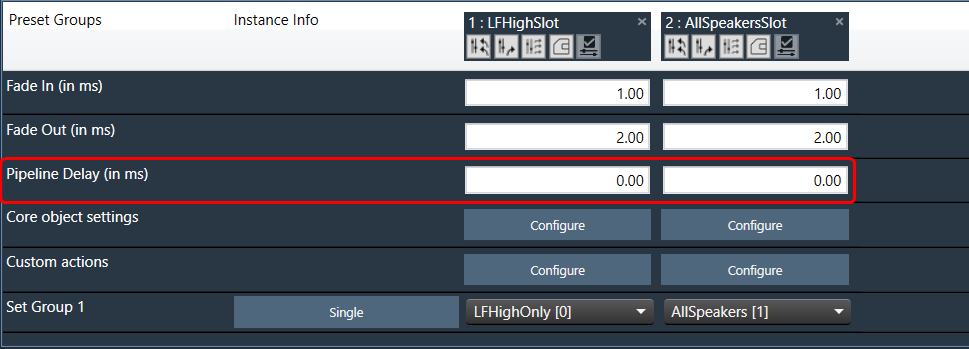
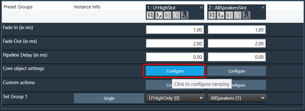
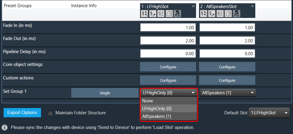
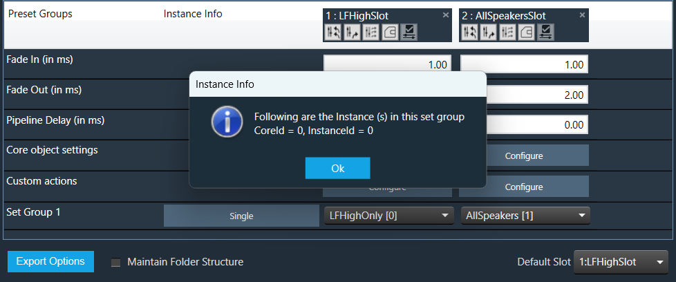
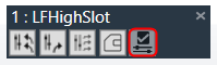
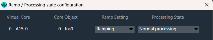
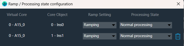
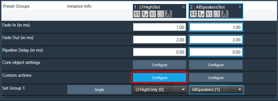
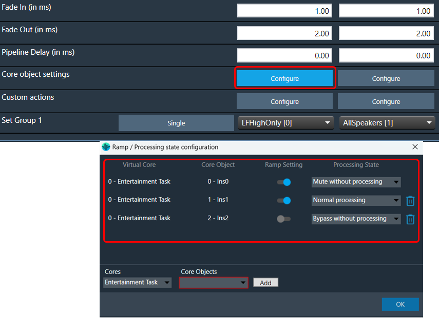
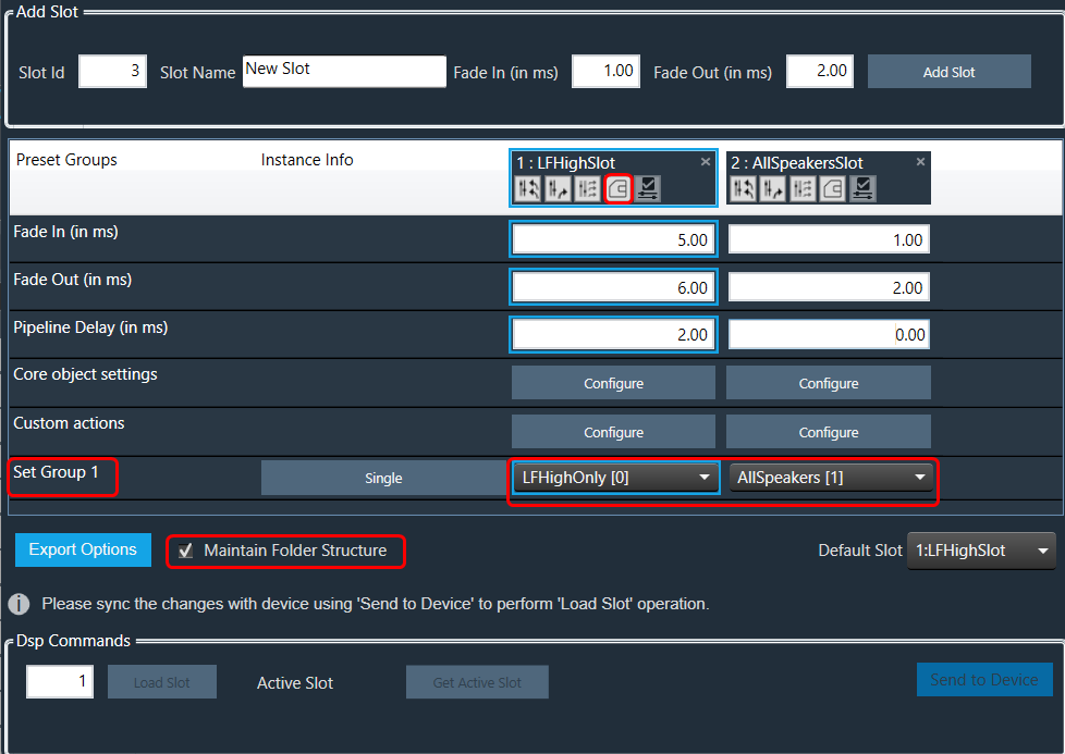
The “Core Object Settings” window is used to control core object transitions and target states. Any core object can be added here optionally, but instances with active set groups for the slot are automatically added.
You can specify which processing state the core object should transition to during the slot load, and if that transition should involve ramping or an instant change.
Core Object Settings includes following processing states:
You can change Ramping state for each instance in a core using drop down option. There are three type of ramping state you can configure.
By default, Ramping is enabled for all instances if not configured.
No Ramping
– There is no rampdown to mute phase before applying preset data (but calc is momentarily disabled during the actual load to protect data).
– There is no ramping between processing state changes.
Swoosh Mode: This mode describes as a seamless preset application, which means in this case no fade-out, mute and fade-in steps are performed. The preset(s) are loaded onto the core objects while calc is running, with a request to tune XTP to attempt ramping.
This mode should be used very carefully, as not all audio objects support ramping during runtime tuning, and not all tunings are guaranteed to be applied without artifacts (audible and/or measurable).
The swoosh mode is stored in the slot map on a per core object basis, meaning that in general the user could apply one preset to an xAF instance in a swooshed manner and another in the normal fade out, mute, fade in manner. This only makes sense if the core objects are running independently, otherwise it could interfere with the swoosh effect in an unexpected and unwanted way. Note: It is possible to select processing states in swoosh mode, but they will not be applied.
Things to know about Ramp state configuration window and how objects transitions will function.
If performing control set custom actions or other non preset object tuning – you may end up with multiple ramps (once from core object and once from AO tuning) multiplying against each other.
– When loading a preset though – the tuning method is called with ramping disabled so the object should not ramp.
Instances which load presets are disabled during the load even if they are unmuted.
The user interface will remain unchanged for Ramp state configuration for audio library versions (S+2).
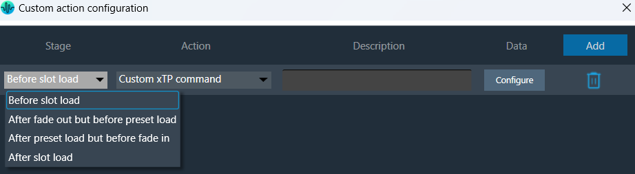
The Preset Controller allows you to configure a “Custom Action” option. Choosing this option opens a dedicated configuration window where you can define custom actions, as shown in the below image.
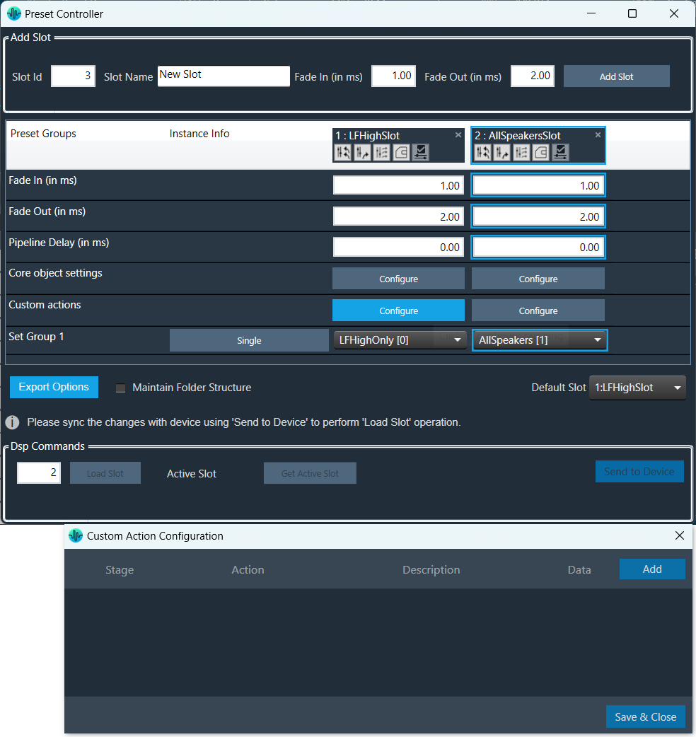
In Preset controller, there is an option to configure what actions have to be performed when a slot is loaded. Currently this feature supports the following actions.
These custom actions can be configured at different stages of slot load. There are 4 stage that can be configured as listed below.
Steps to configure custom actions:
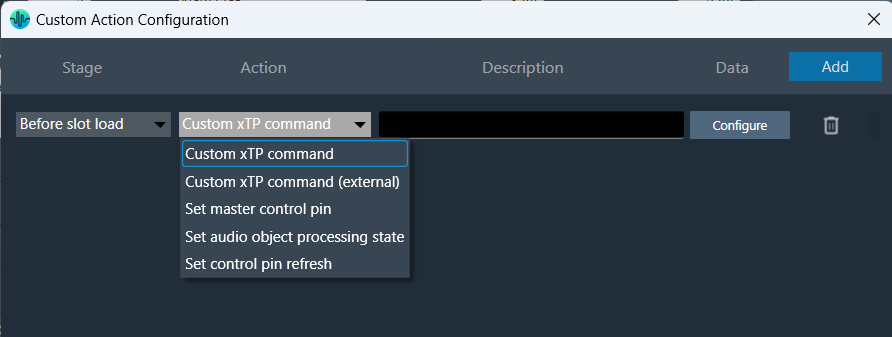
The data configuration option depend on the type of “Action” you choose from the drop-down. Below are the configurations for each supported action type.
| Custom xTP command | 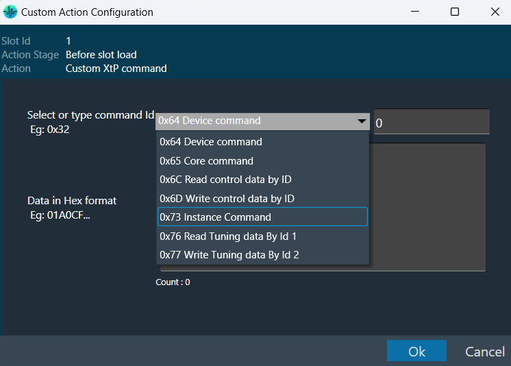 |
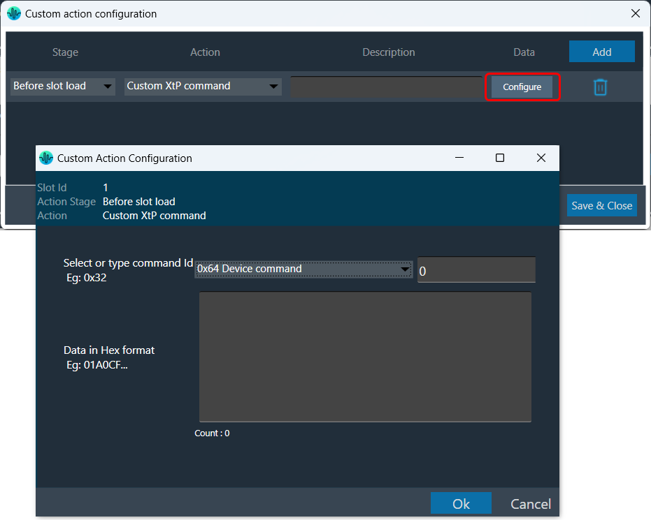
This action sends an xTP message of your choice into the device (as if it received it from GTT).
The commands which go to the core may send a response to the network after processing. These responses may not cause a GTT update depending on the command. The same limitation applies to read commands, for example reading a control value won’t cause GTT to update the value in the explorer. You can select a xTP command from the drop-down. If the command is not available (perhaps in that case you are using a custom command), you can enter command Id in the text box. Then you can enter the command data in the box provided. This window lets you enter data in hexadecimal format. As you enter the data, the count at the bottom keeps track of the characters, helping you ensure the correct length. The system automatically generates a clear description to help you understand the configured custom action. |
| Custom xTP command (External) | 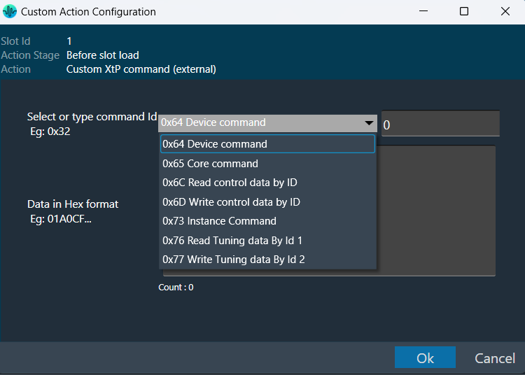 |
This sends a command from the system to the extrenal device or any connected tool from the context of the xTP Interpreter.
You can select a xTP command from the drop-down. If the command is not available, you can enter command Id in the text box. Then you can enter the command data in the box provided. This window lets you enter data in hexadecimal format. As you enter the data, the count at the bottom keeps track of the characters, helping you ensure the correct length. The system automatically generates a clear description to help you understand the configured custom action. |
| Set master control pin | 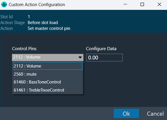 |
This is equivalent to sending the control and value from GTT or from any other xTP source.
This window appears when you choose “Set master control pin” as the action in the main custom action configuration window. |
| Set Audio object processing state (beta) | 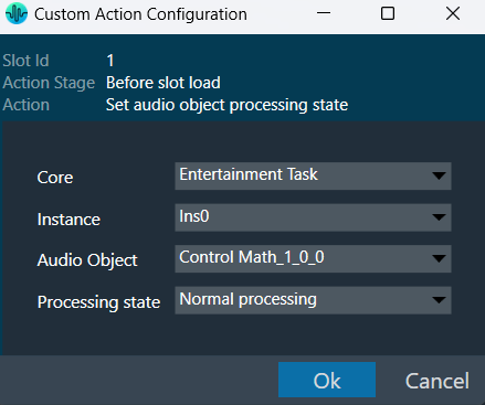 |
Sets the selected audio object to the chosen state.
This window appears when you choose “Set audio object processing state” as the action in the main custom action configuration window. This window will show where you can configure the processing state of the audio object. Once the values are selected, Click “Ok” to save the processing state information. |
| Set control pin refresh | 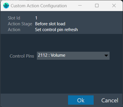 |
Select the action -> Set control pin refresh in the action dropdown.
When the slot is loaded, select the control pin that needs to be refreshed. This data will be sent to device as part of slot map. When the slot with this data is loaded, the configured custom action will be executed on the set control pin. |
Once all the slots are configured with set of actions, the custom action window will appear as per below image. You can override the default descriptions yourself after you configure the action.
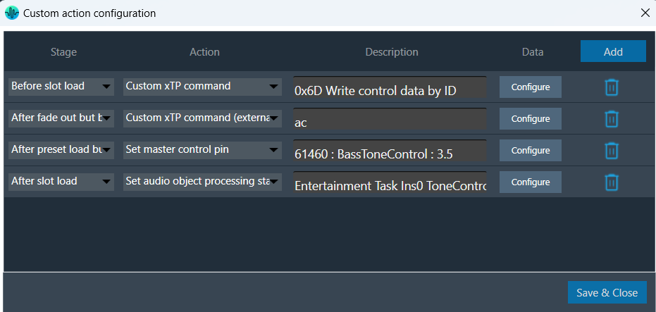
The custom action data configured will be saved only when “Save and close” button is clicked in main custom action window.
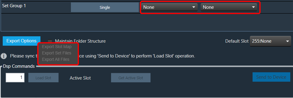
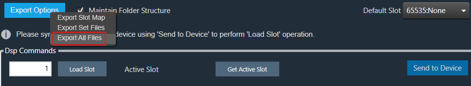
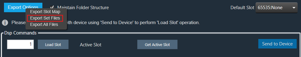
You can export Preset Configuration using the following methods:
Right-click or click on “Export Options” to select the type of export.
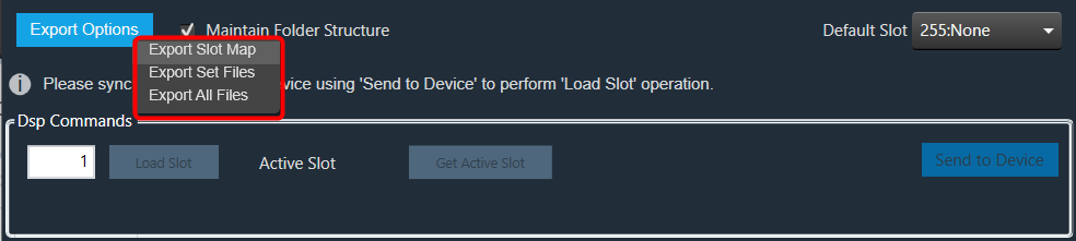
To export a slot map set file, all files should contain at least one valid slot; otherwise, the options Export Slot Map, Export Set Files, Export All Files, and Export Slot will be disabled.
Exporting human readable flash file: The exported flash file can be helpful in case any slot gets accidentally deleted. You can reconfigure Preset Controller values using the slot map table details mentioned in the exported flash file.
Once you have configured all parameters of the Preset Controllers, it is recommended that you export the flash file.
Steps to export human human-readable flash file:
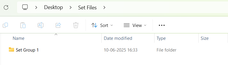
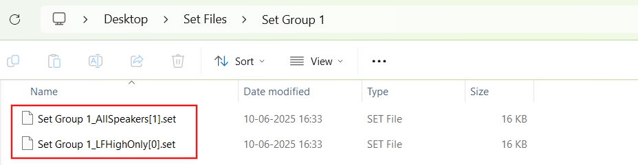
When the “Maintain Folder Structure” option is checked, then all the set files will be generated within a folder named after the Presets Group name, using the format “Presets Group name_SetNamePresetIds”. This applies when performing operations such as Export Set Files, Export All Files, and Export Slot. On the other hand, if this option is unchecked, all the set files will be stored in the chosen path directly.
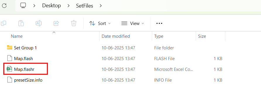
So for above Preset Group (Set Group 1) and sets (Set 1[0], Set2[1]) below folders and file will be created under selected path.

Maintain Folder Structure flag will be persisted while exporting/importing projects and reopening the preset controller window.
If a set of files and slot map files are already available on the device.
By default, the first valid slot in the table is loaded. If the device is offline, it will be automatically connected to it.
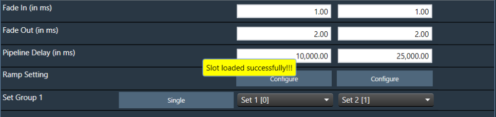
The GTT sends a slot load request to the device and waits for a response. If the device is successfully loaded into the slot, a success message is displayed on the screen.
An error message will be displayed on the screen if the device has failed to load into the slot.

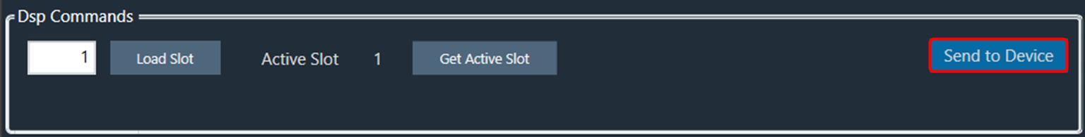
If a slot does not exist in the table but is present on the device, it is also possible to load it. In this case, the user can manually enter the slot ID and click on the “Load slot” button.
When the “Load Slot” command is sent to the device, the device can respond with the following options.
Option 1
Two responses one after the other.
Option 2
Single Error response – Slot loading failed.
In the first two cases, between the first response and the second response, you will be blocked from taking any action in GTT.
The following progress dialogue box will be displayed.
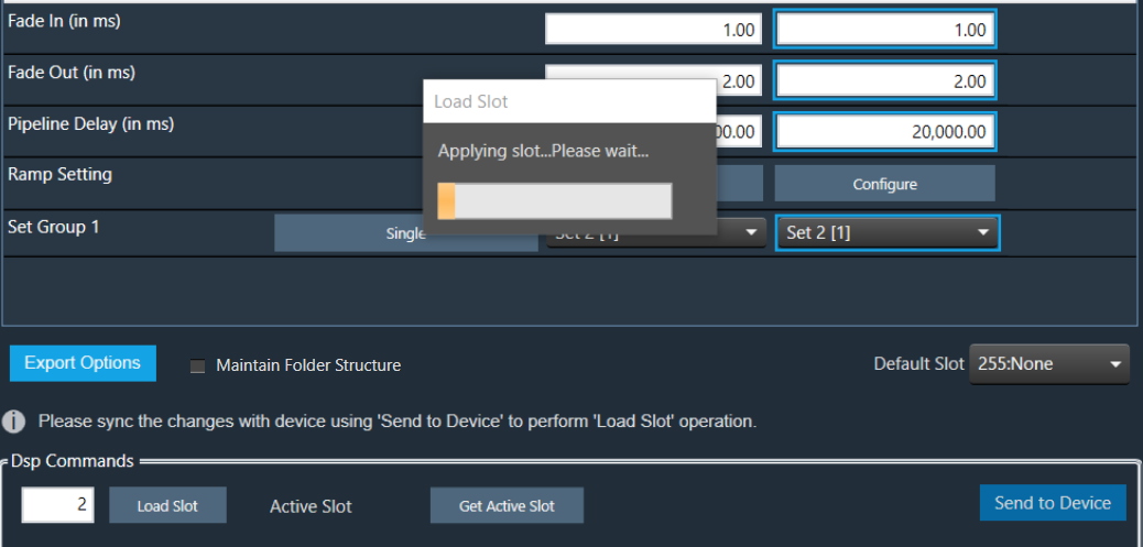
If the second reply is not received within 15 seconds, GTT will unblock itself and report an error.
Steps to send preset data online:
The default slot is the slot number loaded at boot. By default, it is set to “255:None”. You can specify the default loaded slot.
When loading the standard slot, the framework does not apply ramps
Once a preset has been flashed, it will not be flashed again, i.e. each preset configured in the slot map will only be sent once.
If any of these commands fail to be sent, the next command will not be sent, and an error message will be displayed.
When the preset data has been successfully sent, a completion message is displayed to indicate that the transmission was successful. If an error occurs, an error message is displayed.