The Level Monitor is intended to measure the level of input; the audio samples are sent to the output without modification.
Use case: This object can be deployed in Level Monitor mode whenever there is a need to measure the level of signal level and in Clip Meter mode to check if the level is causing clipping. The same input is sent as output without modification.
Level Monitor Properties
Below table describes the Level Monitor audio object properties and functionality.
| Properties | Descriptions |
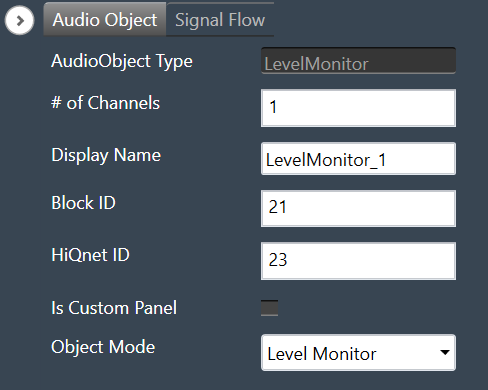
| # of Channels | In the Signal Flow Designer (SFD), the number of control outputs is equal to the number of audio channels. Each control output writes out the channel level/clip indication value based on the MODE selected.
|
| Display Name | Display the name of the Level Monitor audio object in signal flow design. It can be changed based on the intended usage of the object. |
| Object Mode | During design time, the audio object channel can be configured in one of the two operation modes.
|
| Additional Parameters | There are no additional parameters available for the Level Monitor audio object. |
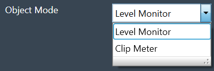
Mode
During design time, the audio object can be configured in one of the two operation modes.
- Level Monitor
- Clip Meter
| Mode | Description |
| Level Monitor | In this mode, the signal level is measured and the value is sent to the control output. This is the default mode. |
| Clip Meter | In this mode, the object computes the signal level and compares it with the threshold set through the tuning parameters. A flag is set/reset if the signal level is above/below the threshold and this flag is sent to the control output. |
Tuning Parameters
Under Level Monitor and Clip Meter mode, the following are the tuning parameters available for each channel.
| Mode | Parameter | Description | Range | Default | Data Type | Unit |
| Level Monitor |
LEV_MODE | To select the method of computation of the input signal level
In all the above types, the computed level is always presented in dB (logarithmic scale) |
0 – RMS
1 – LINEAR 2 – PEAK |
0 | Float | NA |
| DB_LEAK_PER_SEC | Amount of dB drop per second in Peak Level mode. | 1 to 60 | 30 | Float | dB | |
| PEAK_HOLD_TIME | Amount of time peak is held. | 0 to 1 | 0.05 | Float | second | |
| Clip Meter | Threshold | The threshold value for the channel to treat a signal as being clipped. | -20 to 20 | -0.25 | Float | dB |
State Parameters
Under Level Monitor and Clip Meter mode, the following is the state parameter available for each channel.
| Mode | Parameter | Description | Range | Default | Data Type | Unit |
| Level Monitor | LEVEL_VALUE | Measured signal level for the channel | -128 to 20 | 0 | Float | dB |
| Clip Meter | Clip Indicator | Clip Indicator for the channel based on the tuned threshold parameter | 0 or 1 | 0 | Unsigned Long | None |
Control Interface
Under Level Monitor and Clip Meter mode, the following is the control output available for each channel.
| Mode | Parameter | Description | Range | Data Type | Unit |
| Level Monitor | Signal Level | Measured signal level for the channel | -128 to 20 | Float | dB |
| Clip Meter | Clip Indicator | Clip Indicator per channel based on the tuned threshold parameter | 0 or 1 | Float | None |
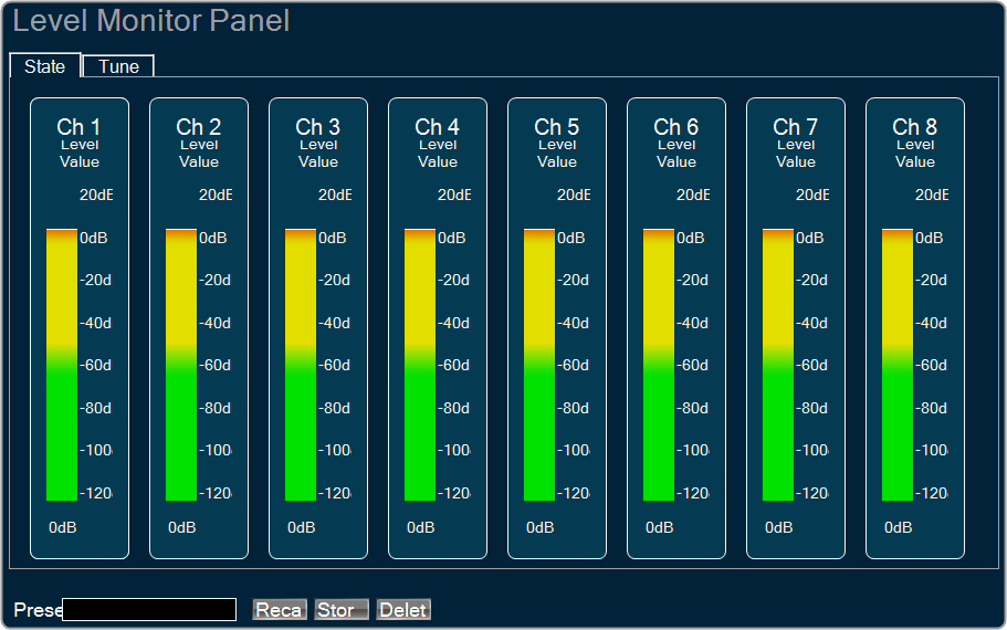
Native Panel
The Level Monitor has native panel and can be used to visualize measurements and to tune measurement parameters, like types of level values. Panel shows as many channels as it is specified in SFD. For more details, refer to Level Monitor Panel.