Using an Analyzer, you can measure and analyze various aspects of an audio signal. It can be used to measure characteristics such as frequency response, amplitude, distortion, and noise level.
You can configure following features to measure and analyze various aspects of an audio signal.
- Banding – For breaking a signal into a number of different frequency bands, and encodes each one independently.
- Mode – For selecting different analyzer modes.
- Advance Settings – For configuring advanced analyzer settings, for more details refer to Advance Analyzer Settings

Banding
In Spectrum or Multiplexer mode, it is possible to adjust the “Banding”. When the banding is turned off, all frequency bins of the spectrum are displayed, allowing for a highly detailed analysis. However, this setting requires more CPU power as the amount of data that needs to be calculated and displayed increases with the FFT size.
Spectrum mode is shown in the example below when Banding is turned off.

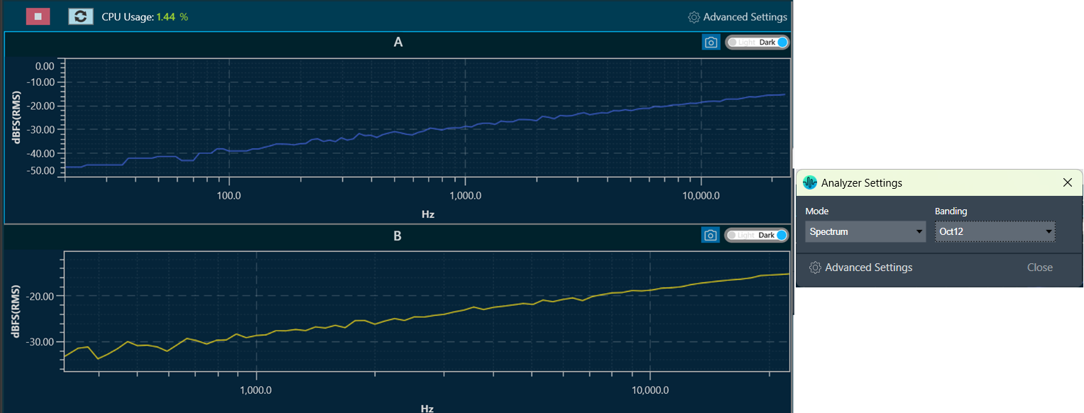
On the other hand, when banding is turned “On”, frequency bins are grouped together. The width of each group can be adjusted by fractions of an octave, such as Oct12, which means that one band has the width of a 12th of one octave.
Spectrum mode is shown in the example below when Banding is turned on.
Mode
Using the Mode option, you can select different analyzer modes from the drop-down list. The available modes are listed below.
- Time: Displays source channels in the time domain (one block of 4096 samples).
- Spectrum: Displays the spectrum of the source channels.
- Multiplexer: Switches the RTA into a multiplexer mode where multiple source channels are combined into two average channels.
- Phase: Displays the magnitude and phase of the source channels. Phase can be wrapped and unwrapped using Graph Settings in the settings window. The phase measurement is done by a dual-channel FFT analysis.
- Delay: Displays source channels in the time domain. The delay measurement is done by cross correlation between a reference channel and a channel that contains the reference signal that went through a certain path (example – amp – speaker – microphone). From the position of the maximum within the correlation result the delay can be calculated. The calculated Delay value is displayed in the Channel viewer in the Delay column.
- IR: Displays the magnitude and IR of the source channels. This is an Impulse response measurement with an exponential sine sweep. When this analyzer mode is selected ‘ExpSweep’
- Generator mode is set, and you are not allowed to change to other modes. The ‘Play’ button is disabled in the Generator view and with the ‘Single’ button he can generate ‘ExpSweep’ once.