The Metering functionality in a signal flow design basically measures the audio signal output and control output from an audio object of the discovered device.
The SFD metering feature is available from V release onwards and supports discovered devices.
The following audio objects are compatible with Control Metering functionality.
– LUT
– Control Math
– Control Smooth
– ControlMultiAdder
– ControlIn
– Control Grouper (Level meter is not usable on ControlGrouper’s control outputs until GTT supports level meter on BlockControl outputs)
To use this feature, you need perform following actions:
- You need to enable Streaming functionality in the device view and configure the parameters.
- Then, you need to add Level Meters in the signal flow design. When a device is connected, you can use Level Meter to monitor the audio output (Peak or RMS values) by adding them to the audio out connections. Similarly, control output value can be monitored in level meters for control out connections.
Enabling Streaming Functionality
In order to utilize Metering feature for each core, you need to enable Streaming functionality.
To enable Streaming functionality:
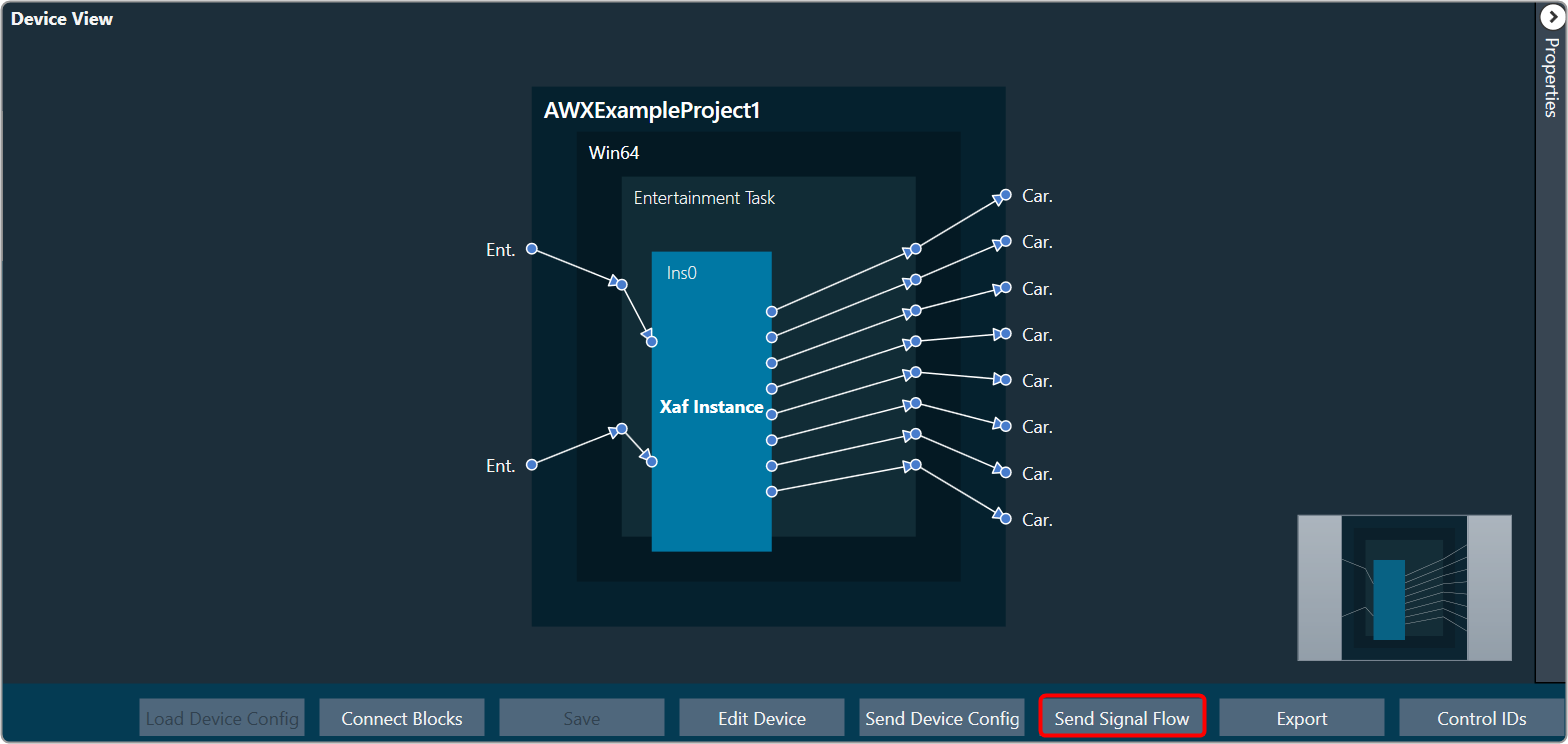
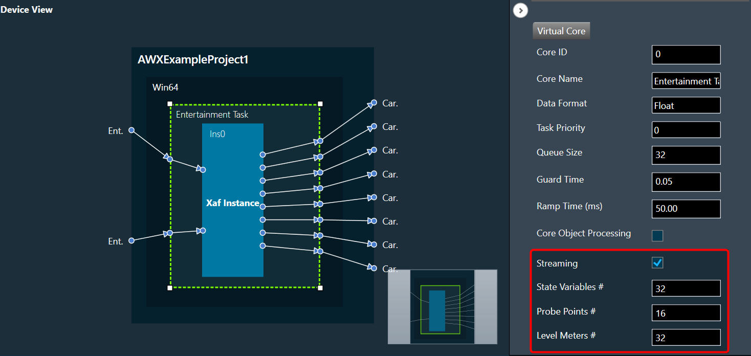
- Open the Device View and select the Virtual core layer of the device.
- Go the Virtual core properties and select the Streaming checkbox. This will enable the Streaming functionality.
Additionally, in the Streaming functionality you need to configure the number of level meters that can be added in the signal flow to monitor control out connections or audio.
A core can be configured with up to 32 level meters, and by default it is set to zero. These values will be sent to device while sending device configuration to allocate required memory for level meter streaming.
All level meters under a core will be deleted if the number of level meters you configure in device view is less than the total number of level meters added in a core.
If you modify any of the Streaming configurations, make sure to perform “Send Device Configuration” operation while connecting device.
Level Meter Panel
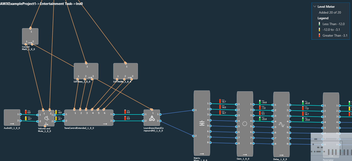
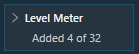
The Level Meter panel displays number of maximum allowed level meters, number of added level meters and the color coding for different ranges of audio output values.
If the streaming is enabled and the number of level meters configured for the core is greater than zero, a Level Meter panel appears in the top right corner of the signal flow designer.
By default, the Level Meter panel is collapsed.
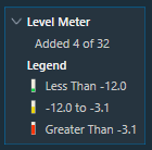
Click on the expand option to view the Legend section. The legend section shows the color coding for various audio output value ranges in addition to the quantity of level meters.
- Green – Peak/RMS value is less than -12.
- Yellow – Peak/RMS value is in the range of -12 to -3.1.
- Red – Peak/RMS value is greater than -3.1.
Configuring Level Meter in Signal Flow Designer
The Level Meter allows you to monitor the audio output and control output in the Signal flow design. In order to monitor you need to add Peak or RMS to the audio out and control out connections of audio objects.
Configuring Audio Output connection
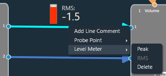
You can view the peak or RMS value of each audio out connection by adding level meters via the connection context menu.
The Peak and RMS are computed based on current block only which means the block length chosen would decide the peak and RMS value. Shorter the block length more fluctuations in peak/RMS value.
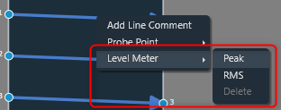
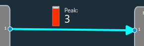
When the Peak option is selected from the context menu, a level meter will be added to the connection to display the connection’s peak output value.
When the RMS option is selected from the context menu, a level meter will be added to the connection to display the RMS value of the output in that connection.

The color of the connection changes when a level meter is added. The color of the connection indicates whether a level meter is present in that connection. The level meter color will get updated dynamically based on the Peak/RMS value of the audio output.
The level meter control and value will not be shown if the device is not connected.
After adding Peak or RMS level meter, delete option will be enabled in context menu. Even the type of level meter can be switched by selecting the enabled level meter context menu option(Peak/RMS).
You can use delete option to remove level meter from a connection. On deleting level meter, level meter control and value will be disappeared, and connection color will reset to default.
Configuring Control Output connection
The Control output value of each control out connections can be viewed by adding level meters through context menu of the connection,
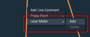
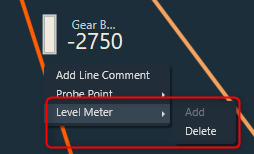
When the Add option is selected from the context menu, level meter will be added to the connection to show control output value of that connection.
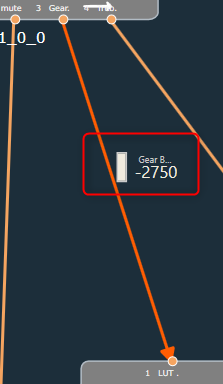
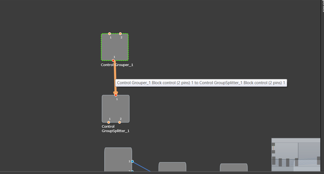
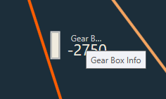
In addition to the control output value, the pin label will be displayed. A tooltip for the pin label has been added in order to see longer pin labels.
The color of the connection changes when a level meter is added. The connection color indicates the presence of level meter in a connection.
If device is not connected, level meter control and value will not be displayed.
Once after adding level meter, delete option will be enabled in context menu.
You can use delete option to remove level meter from a connection. On deleting level meter, level meter control and value will be disappeared, and connection color will reset to default.
While configuring Level Meter in signal flow designer, you can Undo or Redo the Add, Delete and Switching Parameter (Peak/RMS) operations.
Keyboard Shortcuts
Keyboard shortcuts are available to add/delete level meters in signal flow designer screen. Following are the keyboard shortcuts available for different operations:
- Ctrl+Shift+P – To add Peak Level Meter
- Ctrl+Shift+R – To add RMS Level Meter
- Ctrl+Shift+A – To add Control Out Level Meter
- Ctrl+Shift+D – To delete Level Meter
Once one or more connections in the signal flow have been selected, the keyboard shortcuts can be used. This option makes it simple to add or remove multiple level meters.
Export and Import Level Meters
While exporting the project, the added level meters will be exported as part of GTTD file. On importing the project, exported level meters will be imported to GTT.
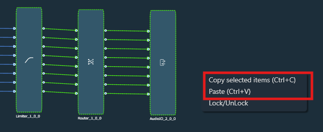
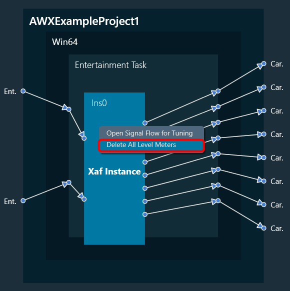
Delete all Level Meters
You can delete all level meters added in an instance by using “Delete All Level Meters” option in instance context menu. GTT will display a message after all level meters have been successfully deleted.
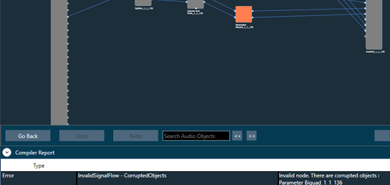
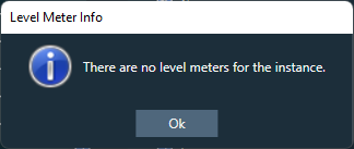
If no level meters are present, following error message will be displayed.
Level meter streaming will get stopped on disconnecting the device. On reconnecting the device, streaming will get resumed for existing level meters if SFD screen is active.
Level meters are not supported for below connections in V release:
– CAO output connections.
– Connections in CAO signal flow.
– Block control connections.