Core Object Settings

The “Core Object Settings” window is used to control core object transitions and target states.  Any core object can be added here optionally, but instances with active set groups for the slot are automatically added.

You can specify which processing state the core object should transition to during the slot load, and if that transition should involve ramping or an instant change.
Core Object Settings includes following processing states:

  • Normal Processing state
  • Bypass without processing
  • Mute with processing
  • Mute without processing

You can change Ramping state for each instance in a core using drop down option. There are three type of ramping state you can configure.

  • Ramping
  • No Ramping
  • Swoosh Mode

By default, Ramping is enabled for all instances if not configured.

No Ramping
– There is no rampdown to mute phase before applying preset data (but calc is momentarily disabled during the actual load to protect data).
– There is no ramping between processing state changes.

Swoosh Mode: This mode describes as a seamless preset application, which means in this case no fade-out, mute and fade-in steps are performed. The preset(s) are loaded onto the core objects while calc is running, with a request to tune XTP to attempt ramping.

This mode should be used very carefully, as not all audio objects support ramping during runtime tuning, and not all tunings are guaranteed to be applied without artifacts (audible and/or measurable).

The swoosh mode is stored in the slot map on a per core object basis, meaning that in general the user could apply one preset to an xAF instance in a swooshed manner and another in the normal fade out, mute, fade in manner. This only makes sense if the core objects are running independently, otherwise it could interfere with the swoosh effect in an unexpected and unwanted way.  Note: It is possible to select processing states in swoosh mode, but they will not be applied.

Things to know about Ramp state configuration window and how objects transitions will function.

  • The ramp time used is configured in the slot, it overrides default core object ramp times.
  • Automatically added core objects (instances with active set groups) cannot be deleted from the list.
  • You can also manually add and remove other core instances and objects.

 If performing control set custom actions or other non preset object tuning – you may end up with multiple ramps (once from core object and once from AO tuning) multiplying against each other.
– When loading a preset though – the tuning method is called with ramping disabled so the object should not ramp.

  • Ramp Setting for instances, which load presets function differently than ramp settings for core object switches or instances which do not load presets.
    • With Ramping on:
      • Core objects and Instances which do not load will use only one ramp if possible.
        1. example: going from normal to mute we do not need to ramp back up after the mute.
        2. example: going from normal to bypass we have to ramp down to mute and then up to bypass.
      • Instances that load presets will always go to mute for loading the preset and then transition to whatever proper state after.
    • With Ramping off:
      • During the ‘muted’ phase which occurs after any rampdowns are finished (if there are indeed rampdowns in the slot) all non-ramping core objects (whether loading presets or not) will instantly switch state to the target state.

Instances which load presets are disabled during the load even if they are unmuted.

The user interface will remain unchanged for Ramp state configuration for audio library versions (S+2).

Configuring Controller Slot

Steps to configure preset controller slot:

  1. Go to the Standard toolbar and open Preset Controller.

    On the Preset Controller window you can see the following details:

    • In the Slot Id, the serial number starting from 1 (or the next available slot) will be displayed.
    • The Slot Name, Fade In, and Fade Out will be filled in with default values.
    • All the Set groups created in parameter sets screen containing the parameters of the device are displayed as rows in set map table.
  2. Enter the values in Slot Id, Slot Name, Fade In, and Fade Out, and click Add Slot.

    A new slot column added with entered details and default value (None) for set groups available in the table.
  3. Enter the Pipeline Delay in the text box. The pipeline delay is used as a delay after applying the preset to the Load Slot operation and before starting to ramp up. The pipeline delay is the time required for the history buffers (which have already been cleared) to be filled with valid data before the start of the ramp-up. The value can be set from 0 to 65535 ms.
  4. In the Core object Setting row, click Configure. This opens the Core state configuration window.
  5. On the Core object configuration window, Enable or Disable ramping for individual core objects using the toggle button.
    Instances which have active set groups in this slot will automatically be added to this window and cannot be removed.
    For more details about Core object configuration, refer to Core Object Settings
  6. (Optional) If you want to add custom actions, in the Custom actions row, click Configure. This opens the Custom action configuration window.
    On this window you define custom actions.  For more details about Core object configuration, refer to Custom Actions Settings
  7. In the Set Group row, click on the drop-down to set a group created in the parameter sets screen.

    If the “None” value is selected for any set group no parameter set from that group is loaded for this slot.
  8. Click on the Single to see the core and instance.
    The instances associated with the set group are shown next to the set group. If the group contains parameters of only one instance, the instance info is “Single”, otherwise it will display “Multiple”.
  9. Double-click on the table column header to edit the slot name.

    Ramp Settings configuration is supported from S+2 device library version.

  10. Click on the “X” icon available on any column to delete the slot.

Slot Options

Retrieve Slot: The Retrieve Slot option in the generic sets window reads the state variable values of all the sets in a slot and updates them in the in the corresponding sets of Parameter Sets. Retrieve Slot button is available in the header of each slot.

Apply Delta Slot:  The Apply Delta Slot feature only send tuning parameter present in the selected slot which are differing for the State variable tree.  The tuning values of the presets are send to the device via XTP Tuning write messages. Apply Delta Slot option is available in the header of each slot.

Apply All Slot:The Apply All Slot feature sends all tuning values of the parameter irrespective of modified or not in the slot. The tuning values of the presets are send to the device via XTP Tuning write messages. Apply All Slot option is available in the header of each slot.

Export Slot: Once you have created a Set Map, click on the “Export Slot” option, and browse the desired path.

Flash file created in binary format. For virtual devices, use the file name as “sect262144.flash”.

Generic sets are persisted in the database, just like any other data in GTT.

Generic sets are also persisted in the .gttd file when the project is exported, and the same is available after importing. The selection of the default slots is dynamic and will not be persisted.

Verify Slot: This functionality is designed to compare the presets loaded on a device with those available in the GTT  in order to ensure their accuracy.

This feature is available only in online mode. i.e. only when the device is connected.

To verify preset values, select a slot and then click the ‘Verify slot’ option. A read command is sent to the device for each state variable within of all presets under a slot. Once the value has been read, it will be compared with the corresponding value in the preset. If all values match, the verification process is considered successful. However, if any values do not match, an error message will be displayed, and an error report will be generated.

Sample error report is as attached here Set 1[2].

Tools

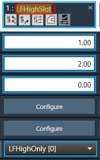
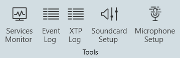
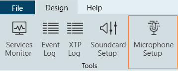
The Tools group allows you to monitor all services running on GTT, view the event and xTP logs, and perform the sound card configuration.

Service Monitor

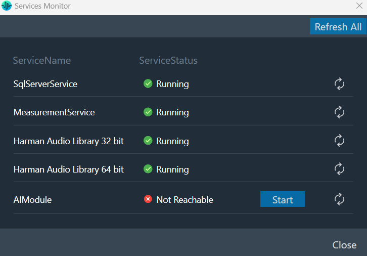
Global Tuning Tool provides a comprehensive set of tools for monitoring the following services:

  • SQL Server Service
  • Measurement Service
  • Harman Audio Library 32
  • Harman Audio Library 64
  • AI Module

The choice of tool depends on the type of monitoring or tuning to be done and the events to be monitored.
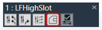
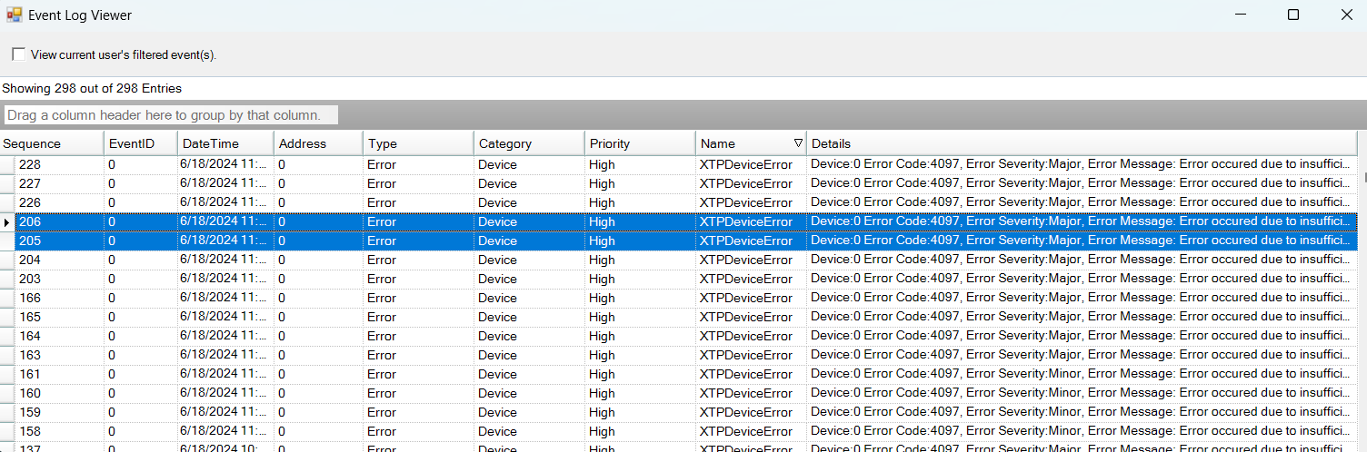
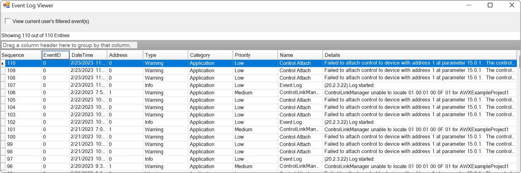
Event Log Viewer

The Event Log window tab shows events that have occurred within the Global Tuning Tool and on connected devices. The log may be utilized by individual devices to perform certain operations. You can also use the logs for troubleshooting.

The Event Log Indicator will notify you in real-time as events occur.
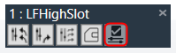
Graphical user interface, table Description automatically generated with medium confidence

xTP Log Viewer

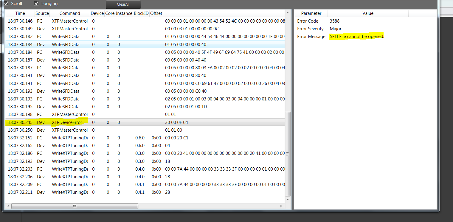
Any error on the device is displayed in GTT in the XTP viewer and Event log.

Graphical user interface, application Description automatically generated

The xTP-Viewer has two sections:

  • Left side section: Display message flow view and show raw data of several messages.
  • Right side section: Detailed view of a selected message on the right side (is empty if message interpretation is not implemented up to now for the specific message).

Sound Card Configuration

The Sound Card Setting allows you to configure the host API (audio driver), device, sample rate, block length, and the master output for the audio processing. Based on device selection, input and output channels are available for configuration.
Using “Master Output” you can set master and device output modes for speaker configuration in the Measurement Module.
The configured sound card configuration is used throughout the RTA and Measurement Acquisition features.

Before you start the Measurement wizard or set the “Sound In” and “Sound Out” devices in the RTA, make sure you have configured sound card settings like Host API (Driver Protocol), Device, Sample Rate, and Block length of the sound card.

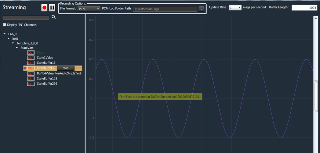
On the “Streams” section list of available channels for input and outputs is displayed. Those can be routed to any physical sound card channels. All devices are available as two-channel devices. The stream area displayed the Channel column, indicating the mapping of Sound In or Sound Out devices to specific channel pairs.

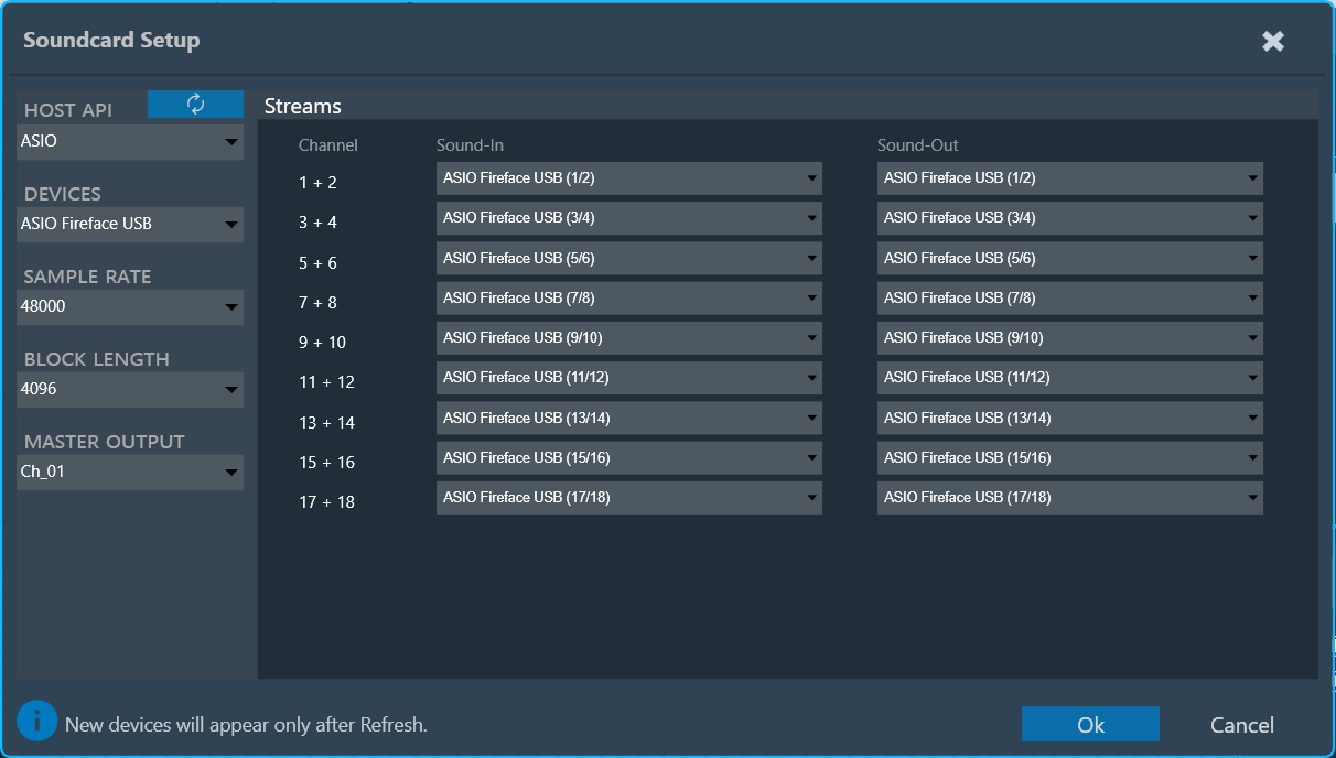
In the example above, the mapping is configured as follows:

  • SoundIn1, SoundIn2: Analog (1 + 2)
  • SoundIn3, SoundIn4: Analog (3 + 4)
  • SoundIn5, SoundIn6: Analog (5 + 6)
  • SoundOut1, SoundOut2: Analog (1 + 2)

GTT supports four host APIs: MME, Windows DirectSound, ASIO™, and Windows WASAPI.

Host API Description
MME This is the standard Windows audio API. It allows the operation of multiple audio devices at the same time. Sample rates are handled by the operating system. Can be set to any sample rate. If the sample rate of the physical audio device is different, then the OS takes care of the sample rate conversion. This mode is recommended if multiple devices are running at the same time, e.g measuring with a USB microphone while playing back generator signals with an internal sound card. For MME, it’s required to select input and output devices separately, and all selected input and output devices support a maximum of 2 channels.

 Recommendation: Keep the block length at the maximum value of 4096 and the sample rate at 44.1 kHz or 48 kHz.

ASIO™ This API is used with multi-channel sound cards. It enables low latencies and ensures that all input and output channels are in sync. Depending on the latency requirements of the audio signal processing provided by a loaded plugin (future feature) the block length can be reduced down to 64 samples. The RTA sample rate setting has to be equal to the audio device driver sample rate. It’s not required to select separate input and output devices for ASIO™.
 Windows Direct Sound This Windows API has improved latency compared to MME as it has more precise buffer control. Sample rate mismatches are handled by the operating system, similar to MME. Input and Output devices are to be selected separately, and they support a maximum of 2 channels.
Windows WASAPI Is Microsoft’s most recent API. Latency has improved compared to MME and Direct Sound. This API does not support an output-only selection, as it requires a clock signal from the input. The operating system does not handle sample rate mismatches; instead, the user is responsible for ensuring that the sample rate of the physical device aligns with the RTA sample rate. Input and output devices must be selected separately, and both support a maximum of two channels.

The following are the limitations of Windows WASAPI

  • Bluetooth devices are not supported.
  • For loopback devices, please ensure that the input device and output device are the same, with the input device name appended with ‘Loopback’.

 – It is recommended to use an ASIO™ sound card instead of Windows drivers if possible.
– When using Windows drivers, it is advised to use a block length greater than 1024 in order to avoid the noise distortion effect and high cpu load issues.
– The setting for the sample rate does not change the actual setting in the sound card driver. The alignment of the sample rate setting has to be ensured by the user.

Supported Soundcards
 -Fireface® UCXII
– TASCAM® US16-08
– Fireface® UC
– Ultralite® AVB, 18 x 18 USB/AVB Audio Interface (Motu)
– Focusrite® – Scarlett 2i4, 2nd Gen
– Creative Soundblaster® X4

During sound card configuration, channel streams should be automatically assigned with available input and output devices if the user has not already assigned any sound input or output devices to RTA Channel streams.

If the user attempts to unassign all sound card channels, a toast message should be displayed with a message like “You have unassigned all sound card channels. This will disable the internal IVP processing, because no lock master is available. Please assign at least one channel pair to re-enable the processing”.

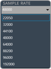
Supported sample rate

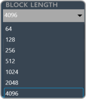
Supported block length

If there are any modifications to the Sample Rate, Block Length, or Host API, it is necessary to reconnect the device Sound card settings impact in RTA

Microphone Setup

The Microphone Setup allows the calibration of microphones and assigns a mic compensation file for each microphone. The configured values will be applied across the GTT wherever microphones are involved, such as in the RTA and measurement modules.  This view can be accessed from the “Microphone Setup” button in the “Design” ribbon tab.

Every microphone element (1 or 6 microphone array) must be calibrated separately. The central element of the calibration menu is the list of microphones contained in the current microphone element.

The list has the following columns:

  • Microphone: The number of the microphone within the element.
  • Sound-In: The stream channel number is configured with the physical channel of the sound card in the Sound Card Setup view. Duplicate channel assignments to microphones are indicated in orange.
  • Previous value: Offset measured during the previous calibration, displayed as a comparison.
  • Current value: The offset measured during this calibration.
  • Compensation File: This is the File provided by the mic manufacturer, which will be used for magnitude curve correction. The current supported format is a .txt file. The supported file format is attached here: M4261-Microphone-4881.

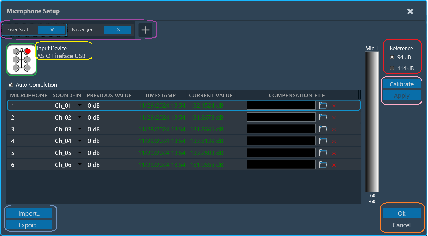
The type of the microphone element and the currently selected microphone within the element are indicated using an icon (green rectangle).
The soundcard and the selected microphone is displayed (yellow rectangle).
The reference sound pressure level of the calibrator can be selected in the upper right (red rectangle).

Multiple microphone carriers can be added or removed (purple rectangle). The currently selected/configurable microphone carrier is highlighted in blue.

To calibrate a microphone:

  1. Choose the Microphone carrier and select the microphone you want to calibrate.
  2. Assign the channel number. Auto-completion will assist in assigning available incremented channels.
  3. Attach the microphone to the designated channel on the calibration device. This will connect the calibrator to the microphone itself.
  4. Select the appropriate reference sound pressure level (SPL) for your calibration.
  5. Click on Calibrate. The calibration process should take approximately 2 seconds.
    While calibration is running, observe the level meter (indicated as a black rectangle) for activity on the chosen input channel.
    The calibration will result in an offset value (displayed in red in the “current value” column).
  6. Click on Apply to accept the value (which will turn the value green) or repeat the calibration process if the value is not satisfactory.
  7. Click Apply confirms the calibration value, turns it green, and automatically selects the next microphone that needs calibration (if applicable).

Repeat the procedure for all microphones in the array.

Individual microphones can be recalibrated at any time. Once all calibration offsets are applied, the menu can be closed using “Ok”.

When configuring multiple microphone carriers, you can easily switch between them, and any changes you have previously configured will be automatically applied.

For any changes in the mic row, the user must click Apply to save the changes before clicking OK.

Import: The “Import” option allows you to import an existing calibration and compensation file path. This sets the current value for all microphones to the stored offsets. The values must be applied. Settings will be imported to the selected microphone carrier.

Export: Using “Export,” you can export a full set of applied calibrations along with the compensation file path to disk. Settings will be exported from the selected microphone carrier. The exported JSON files will contain the Channel Number, Offset, and mic compensation file of the calibrated microphones.

Preset Comparison

Using the Compare Presets feature to compare preset values between two columns.

By default, the Compare Presets feature is inactive. When you select two preset columns, it becomes active.

Steps to compare preset values:

  1. On the Parameter Sets tab, select first preset column, then press “Ctrl” and select the another preset column.
    This will make the Compare Presets feature active and other features such as the New, Duplicate, Default Values, Retrieve, Apply Delta, Apply, Verify, Save, Load, Delete, and Presets column Context menu will become inactive.
    Additionally, when two preset columns are selected, the Next, Previous, and Clear Comparison option will also be inactive; they will only become active if there is a mismatch values available in the selected preset columns.
  2. Click on Compare Presets to compare the values in the selected preset columns. All the mismatched cell will be highlighted in the selected preset columns and the Previous, Next, Clear Comparison options will be in active state.
    Use Previous and Next option check the mismatch value for the particular row.

On comparing both the selected preset columns, if no mismatch found, GTT will display “Both Presets are identical” message.

Presets Comparison will not be persisted when switching to the ‘AO Visualization’ view, but it will be persisted in the ‘Checksum Visualization’ view.

If you attempt to select the third preset column, GTT will prompt a message that “2 presets have been selected already.”

  • Next: Use this option to navigate to the next mismatch value. When you click on Next, GTT will take you to next mismatch row. If you reach to the last mismatch row and the you click Next; GTT will take you to the first mismatch row.
  • Previous: Use this option to navigate to the previous mismatch value. If you are on the first mismatch row, and then you click Previous; GTT will take you to the last mismatch row.
  • Clear Comparison: Use this option to clear all the highlights from mismatch cell background.

When you unselect the presets columns, all Preset Comparison options will be in inactive state.

File Controller

The File Controller allows you to send any type of file(s) from GTT to the device. It does not restrict file type or extension and allows file sizes up to 4GB.

The audio object is responsible for validating that the file being loaded is of the correct type. The file controller does not check the IDs used in audio objects.
Developers and system designers must verify the correct file type when using the file controller. For example, a configuration file should not be loaded into a file player, or a WAV file should not be used as an audio object configuration.
The audio object will return an error state if any invalid file type is detected, and this error must be handled appropriately.

The following are the options available in the file controller.

The file controller feature is available from W release onwards.

Select Workspace

The Select Workspace option allows you to browse and select a workspace or root folder from the local directory. Once the folder is selected, you can add the respective audio files.

Also, you can copy and paste the path of your workspace folder in the “Workspace” field.

Add Files

Once the workspace folder is selected, click on the “Add” to launch file browser. You can navigate to the respective folder and add audio files (.pcm/.wav) in file controller from the workspace folder.

The file browser will open the workspace folder by default.

After adding the files, the following details of the files will be displayed in the file controller.

  • File ID:  This ID is generated from GTT; its range is from 1 to 254.
  • File Name: If the file name is exceeding length of 15 characters (including file extension), GTT will trim it to 15 characters.
  • Path: Relative path of file, based on the workspace folder selected.
  • Size: Size of the file in KB. If the file size is less than 1KB, the size will be displayed in bytes.
  • Checksum: Checksum calculated using file content.

In case if you add any file from a non-workspace folder, the following prompt will appear.

  • Copy: To create a duplicate copy of the file within your workspace folder.
  • Move: To relocate the selected file to your workspace folder, removing it from its original location.
  • Cancel: To stop the ongoing operation.

This facilitates the sharing of project files and files added to the file controller by ensuring that all files added to the file controller are present in the workspace folder.

The number of files added will be displayed in the File Controller.

A maximum of 254 files can be added in the file controller.

Once after adding files to the file controller, on relaunching the file controller, if any file is not found to load, the error is indicated by showing “0 Bytes” size and invalid checksum as below,

Delete Files

The file controller offers two ways to manage your files:

  • Click “Delete All” to remove all files at once.
  • Use the “Delete” button for each file to remove them individually.

The delete operation will delete the file entry from the file controller, not the file from the file system.

Replace File

You can replace file in the file controller. Click on the “Replace” button, this will open the file browser, allowing you to select the new file you wish to use.
Also, allows you to reuse the file ID for different files easily.

Send to Device

The “Send to Device” allows sending the loaded files in the file controller to the device.
While sending files to device, the file map will be sent to device first. It contains metadata (number of files and sizes) about the files being sent.
If it fails to send the file map, the files will not be transferred to the device.

Verify Checksum

The “Verify Checksum” feature helps ensure you’re working with the correct files. The Verify Checksum option uses the file content checksum to confirm that a file with the same file ID is present on the device.

Use the “Verify All” button to check all files at once, or the individual “Verify” button in each row for specific files.

Indicates the default state is “Not Verified”.
Indicates when the file is found on a device with the same file ID.
Also, when the file is sent to the device successfully.
Indicates when the file is not found on the device with the same file ID.

Export Options

To export files from the file controller, the following options are available.

  • Export File Map
  • Export Audio Files
  • Export All Files

These options will be displayed on clicking the “Export Options” button.

Upon selecting any of these options, a folder browser will open, allowing you to select the destination folder.

  • Export File Map: This option is to export the file map and human-readable file map.
  • Export Audio Files: This option is to export audio files added in the file controller.
  • Export All Files: This option is to export all files, including the file map and human-readable file map.

Export and Import File Controller Data

The selected workspace and metadata of loaded files in file controller can be exported through project file (.gttd). This metadata includes file ID, name and relative path of file. After importing the gttd file with file controller data, if the workspace folder is not found, files will be displayed with “0 bytes” Size and invalid checksum as shown below.

You can select workspace folder with same sub folder structure to automatically reload files loaded in file controller. The files should be present in same hierarchy and name.

Send Preset Data Online

Steps to send preset data online:

  1. Connect to the device.
  2. Click on Send To Device under the DSP Commands section. The Preset Configuration, Slot Map, and Presets are sent in sequence.

Graphical user interface, text, application Description automatically generated

The default slot is the slot number loaded at boot. By default, it is set to “255:None”. You can specify the default loaded slot.

When loading the standard slot, the framework does not apply ramps

Once a preset has been flashed, it will not be flashed again, i.e. each preset configured in the slot map will only be sent once.

If any of these commands fail to be sent, the next command will not be sent, and an error message will be displayed.

When the preset data has been successfully sent, a completion message is displayed to indicate that the transmission was successful. If an error occurs, an error message is displayed.

Switch between Multiple Parameter Sets

To switch between multiple parameters, follow the below steps:

  1. Create a new panel as instructed in the chapter Create New Panel.
  2. Drag and drop a set group with multiple parameters sets to the panel and select Button – Radio from the upcoming menu.
  3. Add Multiple Parameter sets to the Panel. The parameter sets will be displayed in the panel.
  4. Click Launch Current. The panel and parameter sets will be launched and appear in a new window.
    Launched Panel with Multiple parameter sets.
  5. Click on the checkboxes to switch between the sets.
    The corresponding settings will be shown in the tuning panel.

Connecting a Device

Steps to connect a Device.

  1. Navigate to the IVP RTA tab and select Advanced from the ribbon bar. This opens the RTA Settings dialogue box.
  2. On the RTA Settings dialogue box, select the Plugins tab, and click on the folder icon to browse the xAF library path.
  3. Set the port number under the Port box.
  4. Enable the Bypass option (optional), if you prefer the input to be passed directly to the next plugin or output without undergoing any processing.
  5. Click on Apply. The number of inputs, number of outputs, and plugin type will be automatically updated based on the provided signal flow. Similarly, you can set remaining plugins.
    Click on Reset (optional), to set back all the values in a specific row to their default values. Now you can configure the analyzer settings like the plugging host, Sound Card Settings, Generator Settings. For more information, refer to RTA Settings.
  6. Switch to Device Designer tab and click on Connect Device to connect to device.
  7. On successful connection with device the Device synchronization dialogue box will appear.

Device Synchronization

On the Device Synchronization dialogue box, you will get the below option.

  • Send: Sends tuning data or control data from GTT to target device.
  • Receive: Receives tuning data or control data from target device to GTT.
  • Not_Sync: No exchange of tuning data between target device and GTT.

The Device Synchronization dialogue box also includes two check boxes.

  • Include state data while receive.
    • If this option is checked and “Receive” operation is selected – The state data will be received from target device along with tuning data to GTT.
    • If this option is not checked and receive operation is selected – Only tuning data will be received from target device to GTT.
    • Checkbox value will be persist per device in GTT.
  • Include control data while send and receive.
    • If this option is checked and “Receive” operation is selected – The control data will be received from target device along with tuning data to GTT.
    • If this option is not checked and “Receive” operation is selected – Only tuning data will be received from target device to GTT.
    • If this option is checked and “Send” operation is selected – Control data will be sent from GTT along with tuning data to target device.
    • If this option is not checked and “Send” operation is selected – Only tuning data will be sent from GTT to target device.
    • Checkbox value will be persist per device in GTT.

The selected data is stored and can be transferred using a .gttd file format for export and import purposes.

Switching off “Include state data while receive” during receive operation might impact synchronization of some audio object panels.

Sending or receiving data is indicated by a progress window along with a percentage of completion of sending or receiving data. The progress bar will close automatically once the send / receive process is completed.

The progress bar window title will be either “Sending data” or “Receiving data” depending on the functionality you have selected.

You can also perform “Send” and “Receive” operation from ribbon bar. To achieve this, the device should already be in a connected state. Following are the options provided as part of context menu.

  • Send Tuning Data: Send tuning data will only send tuning data from GTT to target device.
  • Receive Tuning Data: Receive tuning data will only receive tuning data from target device to GTT.
  • Receive State Data: Receive state data will only receive state data from target device to GTT.

If EOC object is present in the signal flow, Progress window will not show the real progress.

In case there is issue with data transfer between device and GTT. a warning message appears asking you to abort or ignore the operation. You can check the device setup and retry the operation.

While sending the data from GTT to connected device, if there is a data transfer issue between the device and the GTT.  A warning will appear asking whether to abort the operation or ignore the error and continue.
You can troubleshoot the issue by verifying your device configuration and then retry the operation.

While sending the data from GTT to connected device, if there is a version mismatch between GTT and the connected device. A warning message will appears asking whether to continue or abort the operation.

Removing Device Instance

  1. Select device and click on Delete. A warning message will be displayed.
  2. Click OK to remove the device instance from the project.

Removing a device instance carries significant consequences, including the deletion of all associated data such as tuning and signal flows.

Record Streaming Data

The streaming data can be recorded and stored in a file using the record button available. There are two supported file formats.

  • Csv file format (.log)
  • PCM file format (.pcm)

The default recording folder is C:UsersUsernameAppDataLocalHarmanGTTPCMStreamingLogs. To change the folder location for the recording, you need to click on “…” button.

Record Streaming Data in csv format

The csv format logs are supported by both polling and streaming state variables. Once you click on the record button, it opens file explorer to choose the location and file name for storing streaming data.

The default file format for storing streaming recordings is CSV.

The recording process is indicated by a continuously blinking button, indicating that streaming is currently being recorded. To stop the recording, simply use the same button.

During the recording process, adding or stopping streaming is not permitted.

The file stores the following information in the streaming data:

  • Buffer Size and Update Rate.
  • Streaming variables names with comma (,) separator.
  • Streaming variable data with comma (,) separator and if any variables have an array of data it is separated by spaces.

Record Streaming Data in PCM format

The PCM format recording only supported by streaming state variable. Once you click on the record button, it opens file explorer to choose the location and file name for storing streaming data.
Prior to commencing PCM format recording, you must ensure the following conditions are met:

  • The State Variable used for streaming is of a streamable type.
  • PCM format is selected as the file format.

The recording process is indicated by a continuously blinking button, an indication that streaming is currently being recorded. To stop the recording, simply use the same button.

During the recording process, adding or stopping streaming is not permitted.

Each state variable’s streaming data is stored in a separate file containing raw data, which can be imported into tools such as Audacity for further analysis or processing.
A date-time stamped folder is automatically created for each recording under the root folder. Inside this folder, a separate file is generated for each state variable being streamed.

File Name Format: {state variable Name} {Channel Name} {Audio Object Name} {sample rate} {duration in seconds}. pcm

Example of sample recorded file.

Pause and Play Streaming

The streaming data can be paused by using the pause button. When the stream is paused, it indicates that GTT Tool stops receiving data from the device internally, and no bandwidth is utilized during this pause period.

To resume streaming, the same button can be used, and it will convert to a play button once data is paused.

It is not permitted to add new state variables or change the update rate while the streaming is paused. However, stopping an active state variable is allowed.