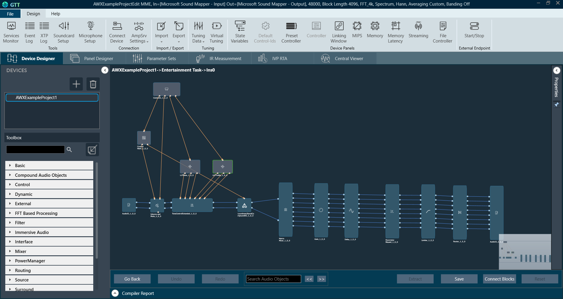
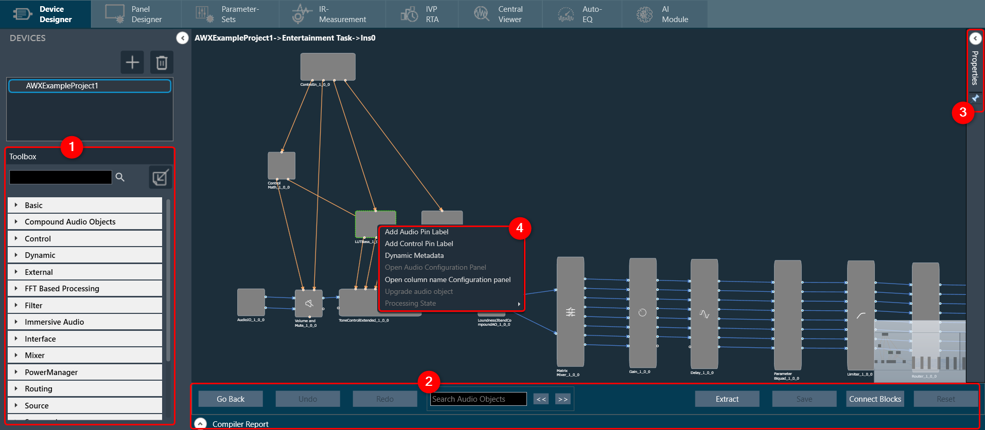
The Signal Flow Designer enables you to create and modify signal flow architecture. It includes a variety of components that you can use to design a signal flow. The components in the Signal Flow Designer are represented as blocks, and you can connect them using virtual connections to create a signal path. You can also adjust various parameters of each component to customize the signal flow according to your needs.
Signal Flow Designer includes the following components:
- Toolbox
- Design Operations
- Properties View
- Audio Object Operations
Toolbox
The toolbox is a library of audio objects. In SFD, you can create compound audio objects by combining multiple audio objects into a signal audio object. These compound audio objects can be saved and reused in the same and other signal flow designs. Additionally, you can import compound audio objects into SFD using the import option.
Use the search option to locate the audio object in the toolbox. To find the desired audio object, enter the first three or more characters in the toolbox’s search bar.
The audio objects displayed in the toolbox are based on the default device audio library version.

Regardless of the audio Library, two objects are always available in the Toolbox by default. The objects “Frame” and “Textbox” can be found in the Shapes category in the toolbox. These are not audio objects, and they are not considered when tuning or sending the signal flow to the device.
The frame object is used to highlight certain blocks in the signal flow designer. Whereas the Textbox object is used to provide additional information to the user of the Signal Flow.
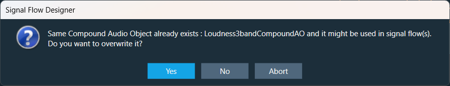
When importing a Compound Audio Object (CAO), if a CAO with the same name already exists, you will see the following confirmation message:
– Yes: To override the existing CAO and update its name.
– No: To create a new copy of the CAO.
– Abort: To cancel the action and prevent the CAO from being imported.
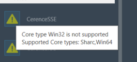
The toolbox will filter audio objects based on the core type of the physical core where this Framework instance is added.
The audio object will be marked with an exclamation mark to indicate that it cannot be used for building signal flow. You can hover over it to see which core types are supported.
For more information about various audio objects, refer to the Audio Object Description Guide.
Design Operations
This section contains several operations you can perform in a signal flow design.

The following are operations you can perform in a signal flow design.
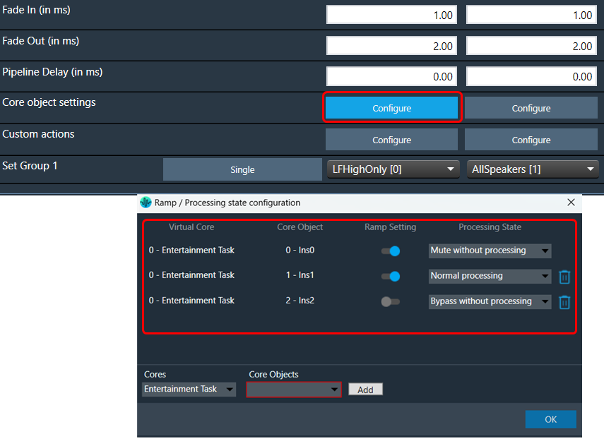
- Reset a Processing state(s): In the signal flow designer, you can reset all audio objects processing state to ‘Normal’ by using the “Reset” button.
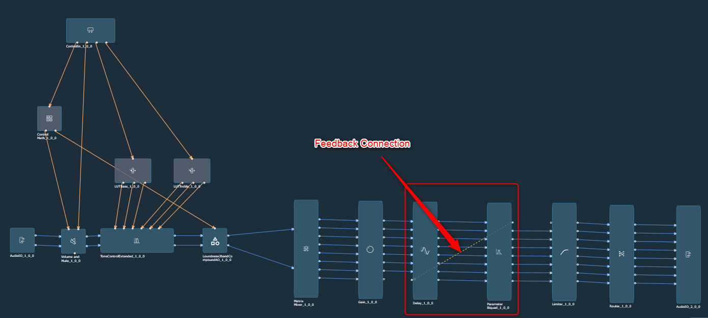
- Connect Audio Blocks: When designing a signal flow for processing audio signals, there are different types of audio objects that are used to create the audio signal. To create a meaningful audio signal, you need to connect these blocks in a signal flow. This concept is called routing.
Routing is the process of directing an audio signal from one block to another. In a typical signal flow, various audio objects are connected from input to output using virtual connections to route the audio signal from one block to another.
You can connect all audio objects with a single click using the “Connect Block” option. Later, you can modify the connections as per your requirements.
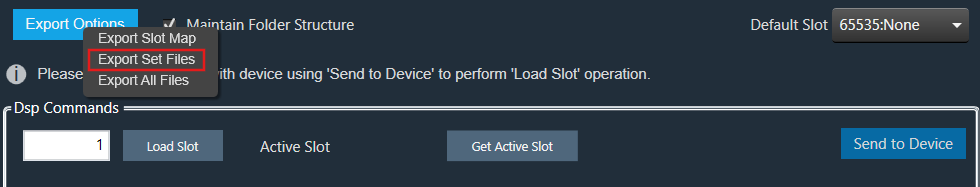
- Saving Signal Flow Designer: When working with a signal flow designer, it’s important to save your work regularly to prevent data loss. This ensures that you can return to your project at a later time. Click on the “Save” option to save the changes in the signal flow design.
- Extracting Audio Object: The Extract can be performed only when valid audio objects are selected. Currently, the GTT does not support FIR MIMO, EOC, RNC, Audio IO, Control IN, or Compound Audio Object extraction.
Extract will be enabled only if Signal Flow is saved.
For extracting audio objects, you need to select one or more audio objects from an existing signal flow and extract audio objects into a Compound Audio Object. The application will replace the extracted audio objects with the Compound Audio Object in the signal flow.
For more details about compound audio objects, refer to Compound Audio Object.
- Search Audio Object: Using the search option, you can locate specific audio objects in the signal flow designer. The located audio object is highlighted in yellow color.
You can use the “<<” and “>>” buttons to move between the highlighted audio objects. When you click the “<<” or “>>” search buttons, the highlighted audio object will be repositioned to the center of the screen.
- Redo/Undo: The redo and undo options allow you to redo or undo the changes that you have made to your audio project.
Press Ctrl+Z to perform the Undo operation, and Press Ctrl+Y to perform the Redo operation.
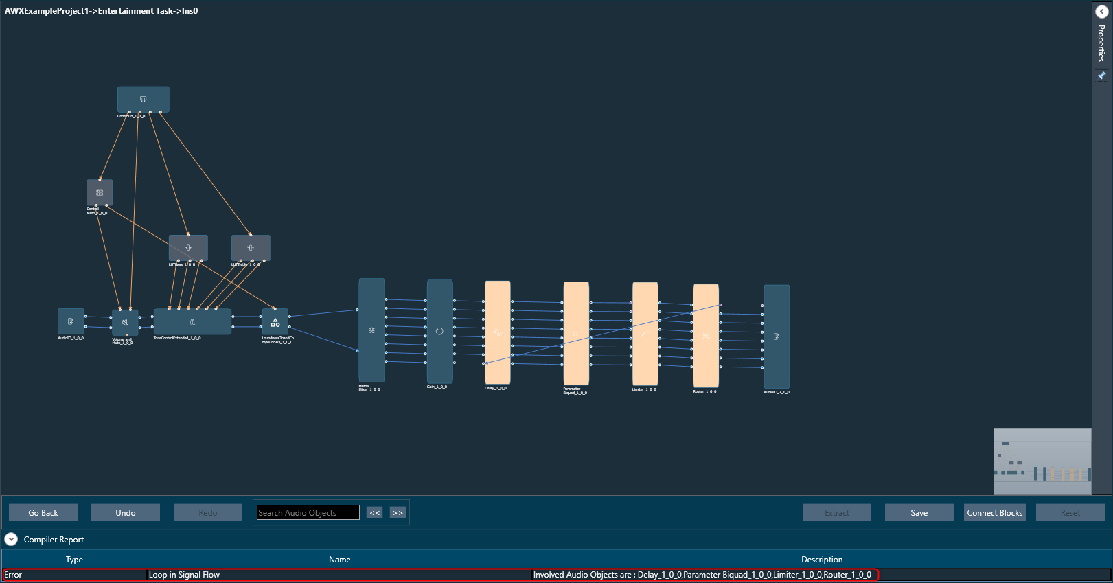
- Compiler Report: The compiler report displays a warning or error message entry item for each invalid audio object.
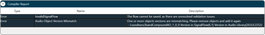
The following are a few factors responsible for invalid signal flow design:
- If the audio object tuning version differs from the existing audio object type in the Device Associated Audio Library.
- Due to the addition or modification of parameters of an audio object, it might mismatch with the signal flow design state.
To resolve the issue, you need to upgrade the audio object; refer to Upgrade Audio Object for more details.
Properties View
You can view the properties of an audio object used in the signal flow design through the Properties view. This allows you to configure the properties of the audio object to suit your requirements. The properties can be viewed by selecting a specific audio object.

Audio Object Modes
Some audio blocks support multiple configuration modes. For instance, the AudioIO block can function as both an audio input and an audio output block. Similarly, the Biquads block can operate either as a parameter-based or a coefficients-based Biquad.
In previous versions of the Signal Flow Designer, each mode of an audio block was displayed as a separate audio block. However, in the latest version of the tool, it is assumed that every block can support at least one configuration mode.
For those blocks that support multiple modes, an extra drop-down field is now shown on the properties view. By selecting an appropriate value from the drop-down, you can modify the mode.

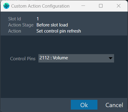
Control Configuration
In the latest version of GTT, the Signal Flow Designer supports control routing from the control hub (Master Control) to xAF framework instances.
The ControlIn object does not support control id configurations from “Y-Release” onwards. The control id configuration is now available on the device level of the Master Control entity. For more information, please refer Master Control.
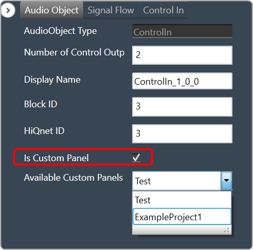
Mapping Custom Panel
Open any audio object property view, enable the “Is Custom Panel” option, and select the appropriate custom panel from the drop-down list.
For details about creating a custom panel in GTT, refer to the link Create a Custom Panel in GTT.
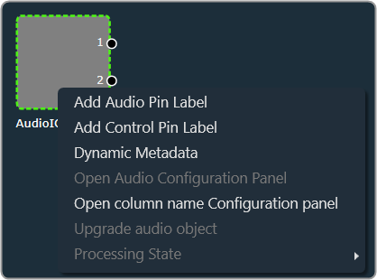
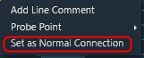
Audio Object Operations
You can access these operations by right-clicking on any audio object and selecting them from the context menu. Below are the options available in the context menu.