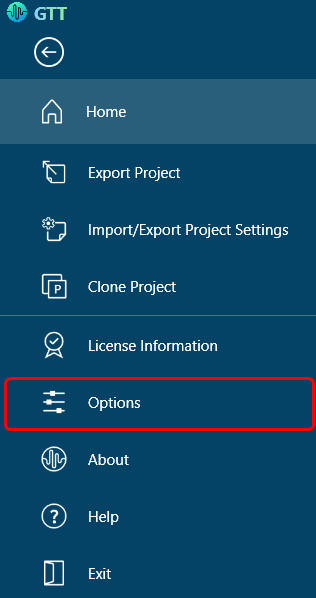
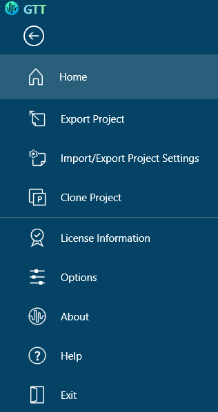
The File Menu on left side of the home screen provides following additional options:
- Export Project: To export a project, for more details refer to Export Project.
- Import/Export Project Settings: To export and import project settings of RTA, Central Viewer and Measurement Module, or more details refer to Import/Export Project Settings.
- Clone Project: To clone a project, for more details refer to Clone Project.
- License Information: Displays GTT license status. Also, you can renew your GTT license., for more details refer to License Information.
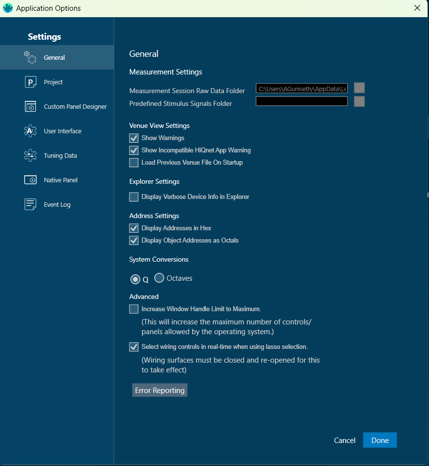
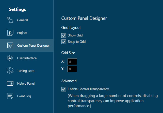
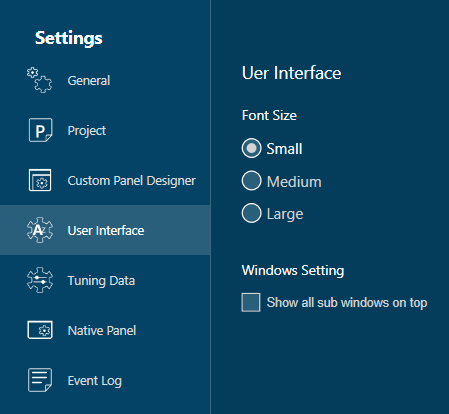
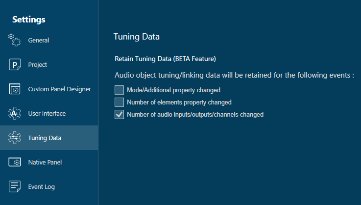
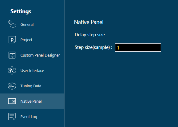
- Options: To configure global tuning tool settings, for more details refer to Application Options.
- About: To know Global Tuning Tool version, release type, and license status.
- Help: To open AudioworX documentation.
Exporting a Project
The Global Tuning Tool allows you to export the signal flow design of the project. This capability enhances your workflow and ensures easy sharing and collaboration.
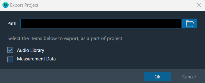
The Export window includes an option to save the file to a specified path and filename, as well as an option to include project dependencies in the gttd file. By default, the “Audio Library” option is selected. You can unselect or select audio library and measurement data options. These options will only appear if they are available in the project.
Steps to export the project:
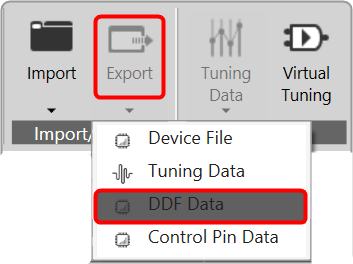
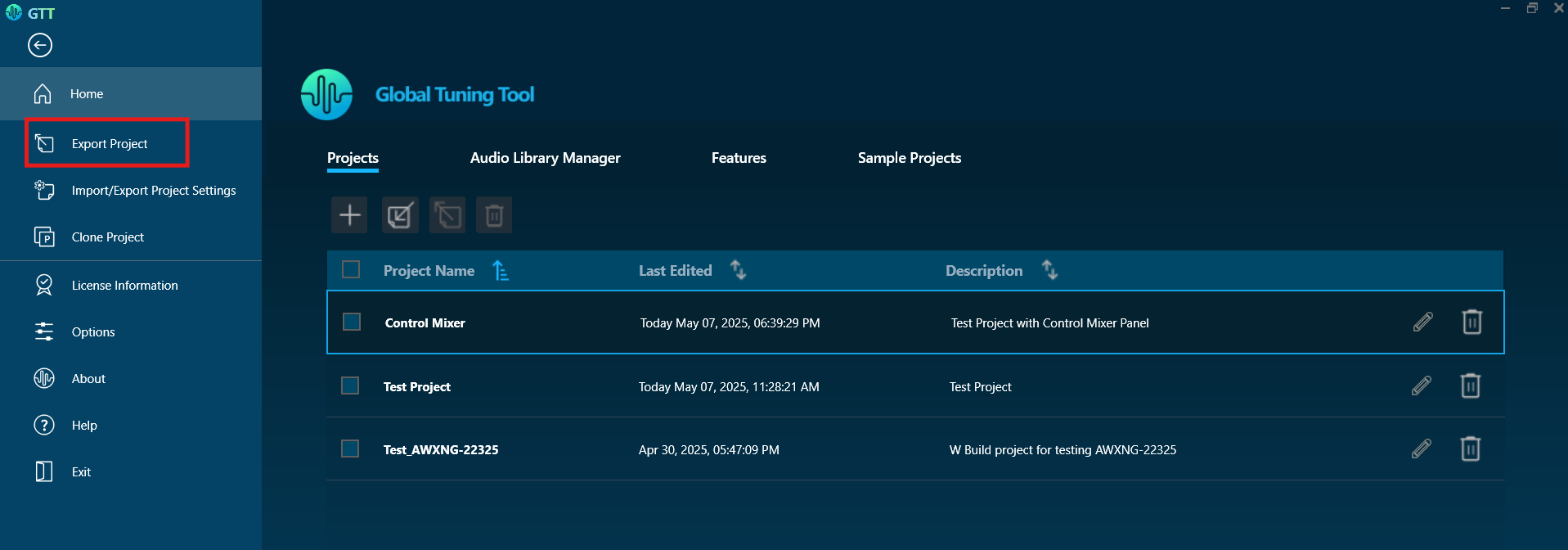
- Go to the Home screen, open the project, and click on the Export Project option.
- On the Export Project window, click on the browse, navigate to the desired location, and then click Save to save the project file.
- Select the project dependencies Audio library or Measurement data option, if you want to include them in the project and click Ok.
The Project export will start.
A message will be displayed after a successful export.
The project file is stored with the file extension *.gttd along with selected project dependencies.
Make sure to provide the path before clicking OK, as this will help avoid any errors and ensure a successful process.
The Audio Library and Measurement Module raw data will be exported as project dependencies in the gttd file, with no additional files included.
Export Project with Measurement Sessions
When a project is exported, by default the project will be exported with measurement sessions and session associated raw data will be stored in the {projectname}.mmdata file in the same destination folder.
If you want to exclude measurement session data from the exported project, make sure to configure the project settings prior to initiating the export process.
Steps to exclude measurement sessions from the export project:
- Click on the File menu and select Options.
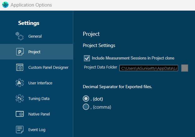
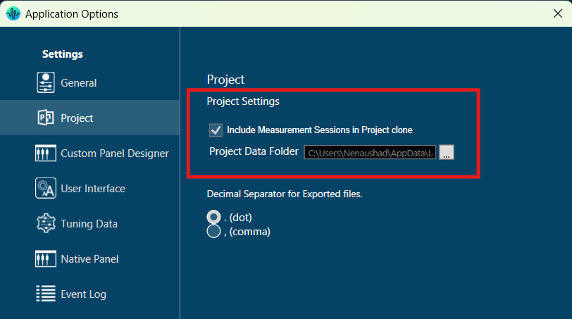
- In the Application Options dialog box, click on Project Settings, and uncheck Include Measurement Sessions in the Project export / clone options.
- Click Done to save the change.
From the X release onwards, selecting the Measurement Data option in the Export Project window will export the associated raw data from the measurement session. No .mmdata file will be generated.
Selecting the Measurement Data option will export the data into a gttd file. Project settings are only applied when cloning the project, as shown in the screenshot below.
Import and Export project settings
The Export and Import project settings allows you to share project settings of certain components like RTA, Central Viewer, Auto EQ, and Measurement Module etc to other team or to a end user.
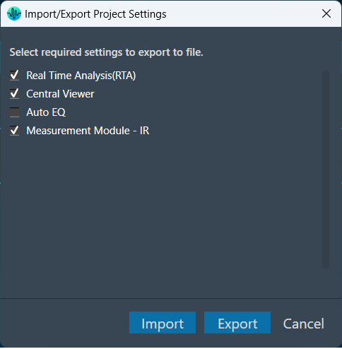
- Export Settings: Allows you to export RTA, Central Viewer, and Measurement Module settings of a project. The settings will be exported as a *.gttdSettings file.
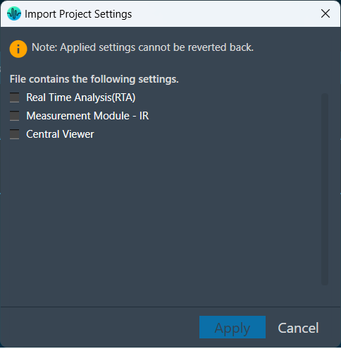
- Import Settings: You can import the previously exported project settings (*.gttdSettings file) after creating a project and wants to replicate the same project environment with the same settings.
During the import process, you can optionally choose to import component-wise settings.
Clone Project
The clone project feature allows to create copy of the project, which includes or excludes the measurement session data.
If you want to include or exclude measurement session data in the cloned project, make sure to configure the project settings prior to initiating the clone process.
Follow the below steps to create a clone of the project:
- On the GTT home window, open the desired project that needs to be cloned.
- Click on the File menu and select the Clone Project option. This action will start cloning the project and copy all the data from the opened project.
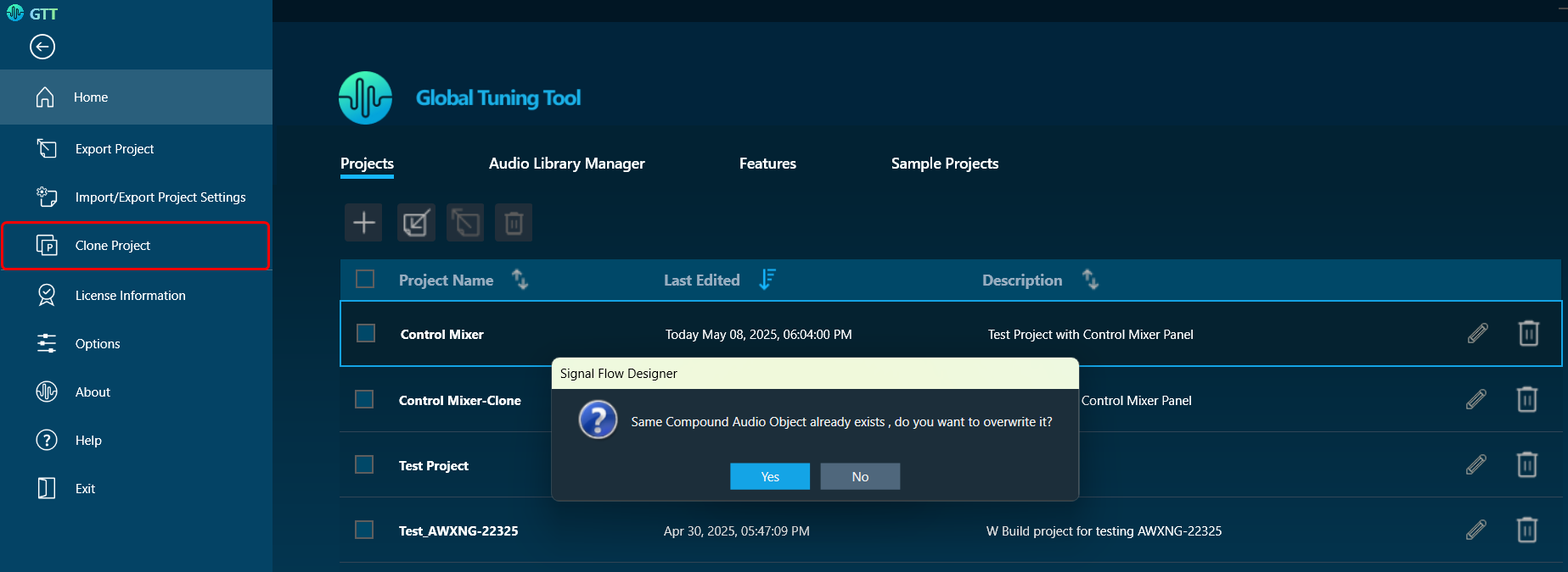
- Once the clone completes the cloned project will be opened.
By default, the measurement sessions will be included in the cloned project.
Include or Exclude Measurement Sessions while Cloning
While cloning you can include or exclude measurement sessions. Additionally, you can store the session-associated raw data in the {projectname}.mmdata file in the same destination folder.
Follow the below steps to configure the project settings:
- Click on the File menu and select Options.
- In the Application Options dialog box and click on Project Settings.
– If you want measurement sessions to be included in the cloned project, select the Include Measurement Sessions in the Project clone options and set the project folder.
– If you don’t want measurement sessions to be included in the cloned project, unselect the Include Measurement Sessions in the Project clone options.
- Click Done to save the change.
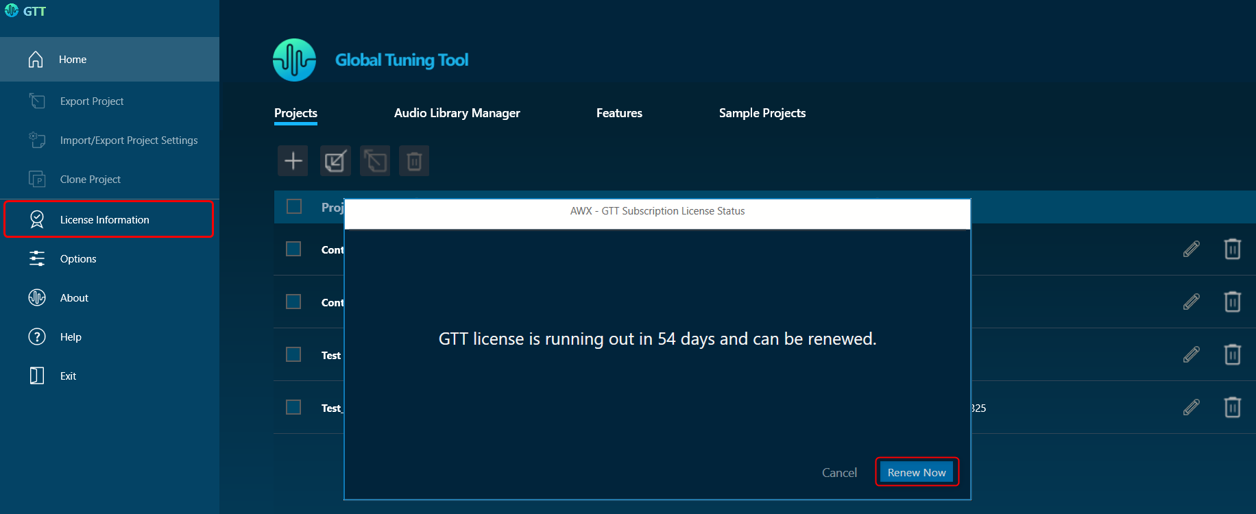
License Information
You might see the “Renew GTT license” message on your GTT platform home page or dashboard. This happens due to an upcoming expiration date of the GTT license.
Click on License Information menu to see the AWX – GTT subscription license status. The license information window has a Renew Now button which enables you to extend the validity of your GTT license, and you may also request new features as part of the renewal process.
The system will start downloading the latest license. The GTT platform notifies you after a successful license renewal.