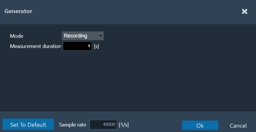
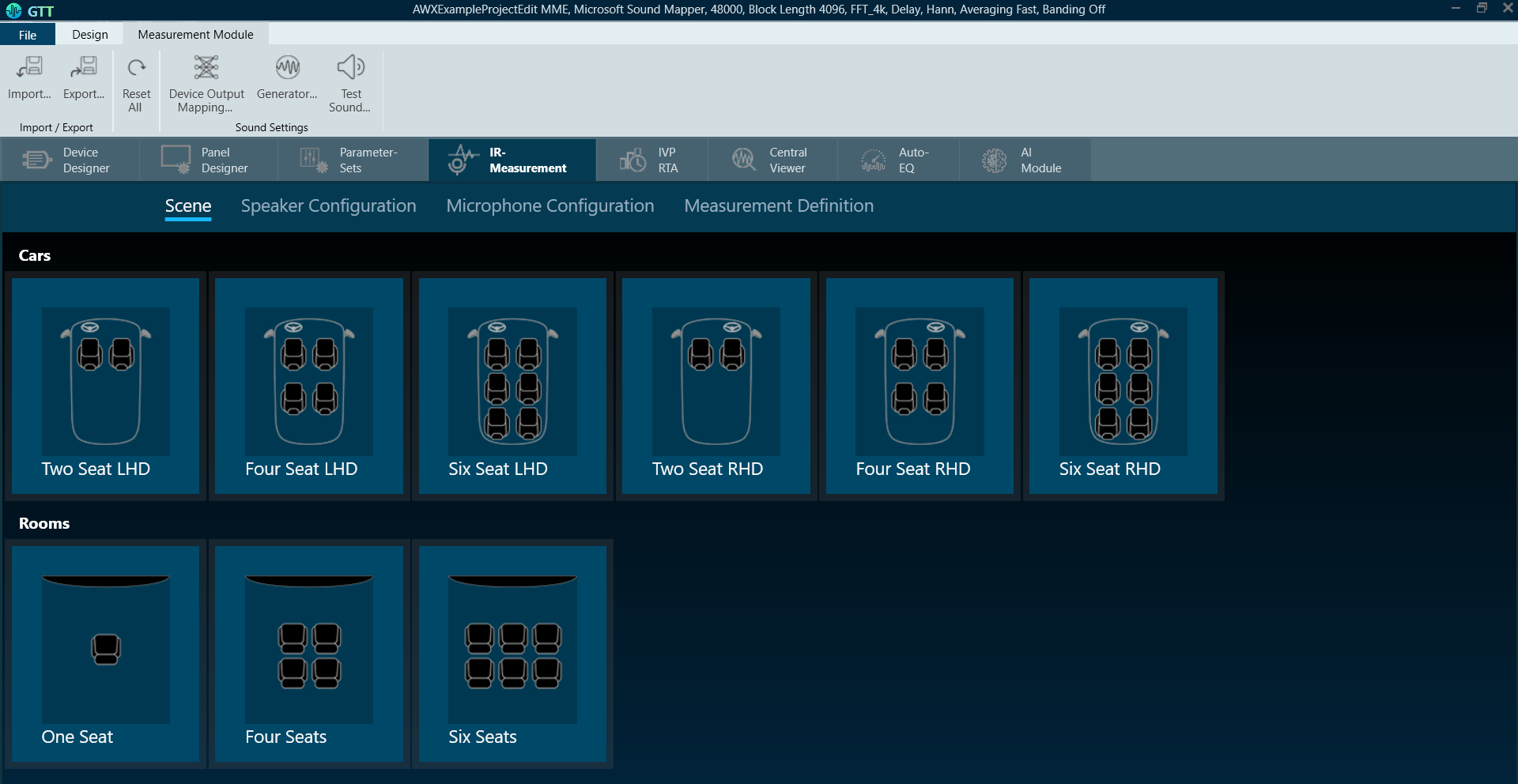
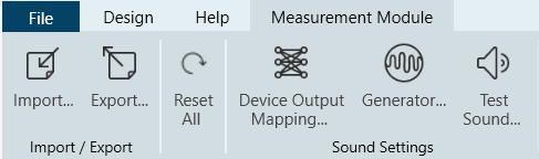
The generator menu is used to define parameters for the signal used in measurements. Using the drop-down option you can select Generator mode.
The generator supports the following mode.
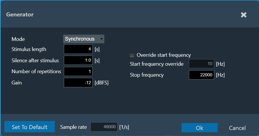
Synchronous Mode
The following parameters can be set in synchronous mode:
- Stimulus length: Duration of the signal in seconds used to measure.
- Silence after stimulus: Stop margin after end of playback, to capture the tail of the sweep signal also in very reverberant environments or over long distances. Takes decimal values.
- Number of repetitions: Number of measurement tools will be, used for average measurement.
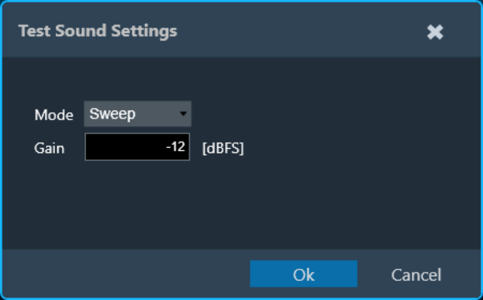
- Gain: Playback gain in dBFS, only integers can be specified, and positive values will be correct to negative.
- Override start frequency: If checked, the value entered for “Start frequency override” takes precedence over individual loudspeaker settings on the speaker configuration tab
- Start frequency override: Lowest frequency of the sweep. Only enabled if Override start frequency is enabled.
- Stop frequency: Highest frequency of the sweep. The value will be hard limited to 1/2* sample rate.
Asynchronous Mode
The following parameters can be set in asynchronous mode:
- Stimulus length: Duration of the signal in seconds used to measure.
- Silence after stimulus: Stop margin after end of playback, to capture the tail of the sweep signal also in very reverberant environments or over long distances.
- Number of repetitions: Number of measurement tools will be used for average measurement.
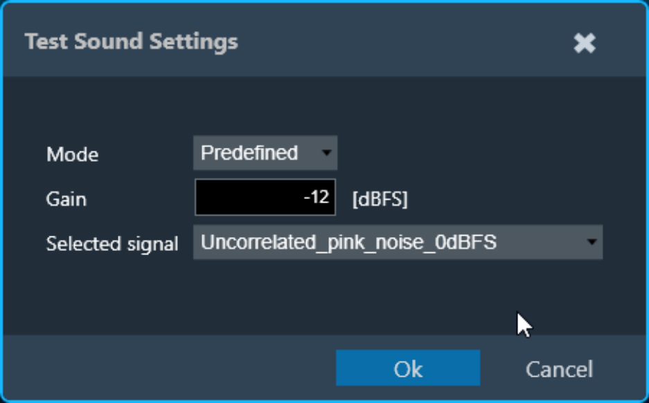
- Gain: Playback gain in dBFS, only integers can be specified, positive values will be correct to negative
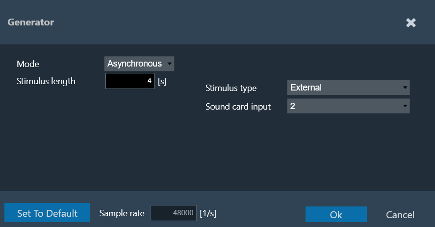
- Stimulus type: Choice between “Predefined” and “External”.
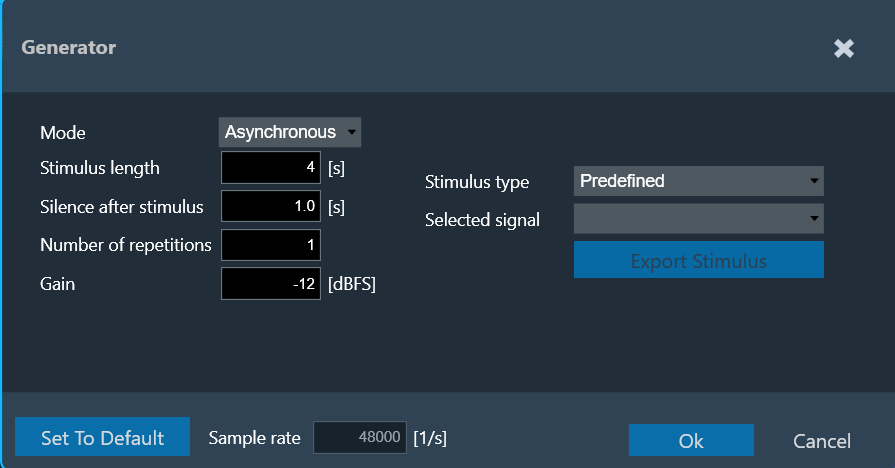
For the “External” Stimulus type, the following additional parameters can be set.
- Selected signal: Signal from the signal library.
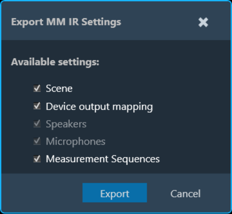
- Export Stimulus: Opens an export dialog to export the signal for manual playback according to the parameters defined in this menu.
- Soundcard input: Selection of the soundcard input used for external stimulus tracking (the measurement on this channel will be used as a reference for the IR estimation). The channels specified here cannot be used as microphone input channels.
The default settings can always be recalled by clicking on Set to Default.
The Sample rate information is read-only. You can “Sound Card Configuration” to modify the sample rate.
The signal library folder for predefined stimulus signals can be set under File > Options > General Settings > Predefined Stimulus Signals Folder.
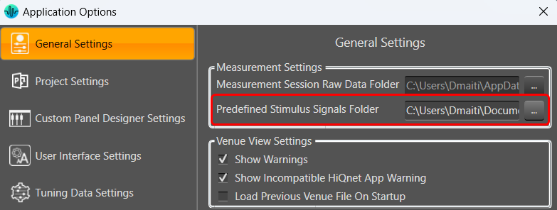
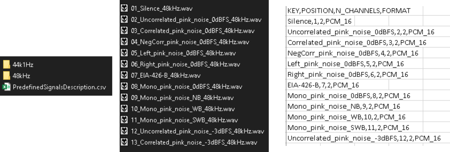
The folder needs to contain a “PredefinedSignalsDescription.csv” file specifying the details of the files, and a folder each containing the wav files all required sampling rates:
The following parameters can be set in recording mode:
Recording Mode
Measurement signal length in seconds for pure recordings without signal generation. The maximum recording length is 60 seconds.