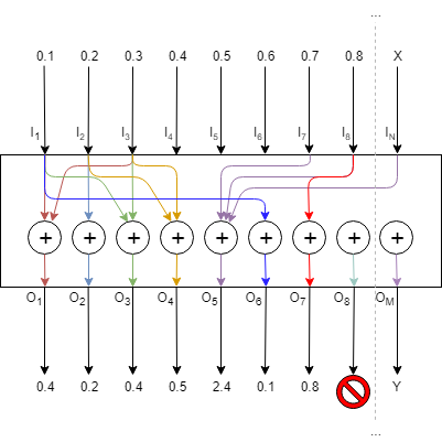
The Lookup Table (LUT) audio object performs a table lookup to create a relationship between a control input and a control output.
For example, the LUT converts the vehicle speed values to gain by manipulating the speed values using a look up table. The LUT module gives out values of multiple 1-D functions (i.e. control outputs) at specific query points using ‘linear’ or ‘nearest index’ or ‘lower index’ or ‘exact match’ Lookup Method.
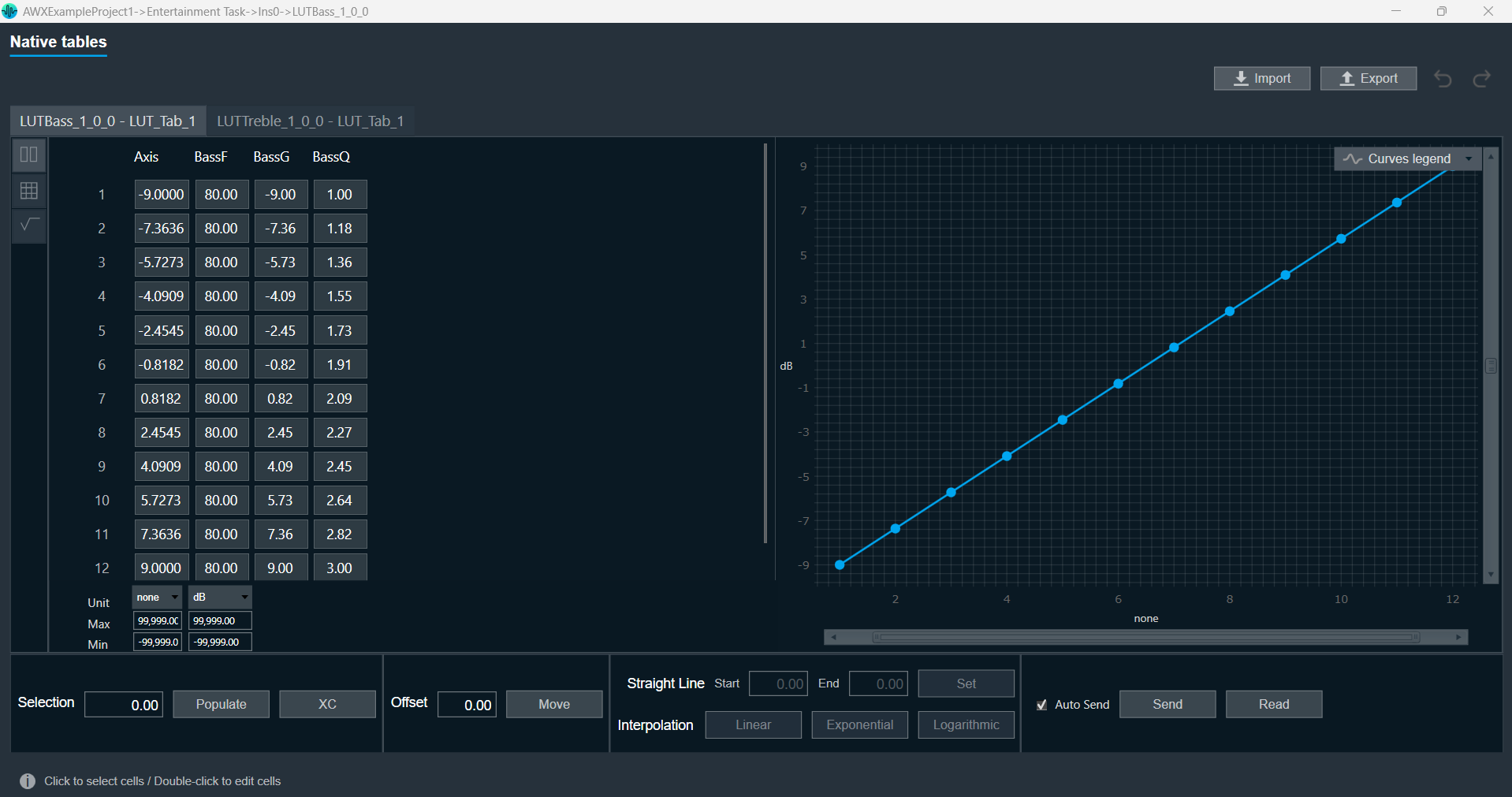
The number of columns in the LUT is configurable by modifying the number of elements from the SFD. The first column of the table contains one independent vector, which corresponds to the x-axis of the interpolation. Each of the corresponding columns corresponds to the interpolation slopes for the outputs. The number of rows of LUT denotes the number of steps in the interpolation of each control output.
The LUT also supports multiple control inputs. This enables LUT to send table values on different set of outputs independently using the same LUT table. This eliminates the need for duplication of LUT objects when the user wants to send table values to different audio objects independently using same table.
The LUT performs the Lookup method (floor, round, linear interpolation, exact match) between values.
- If the control input is below the minimum value in the x-axis and the lookup method is linear interpolation / lower index / nearest index — then the LUT will output the minimum value in the table. If the lookup method is an exact match, then there will be no output.
- If the control output is above the maximum value in the x-axis and the lookup method is linear interpolation / lower index / nearest index — then the LUT will output the maximum value in the table. If the lookup method is an exact match, then there will be no output.
In addition, LUT supports Axis Linearity and, when enabled, LUT optimizes interpolation and assumes equally spaced steps of interpolation, i.e x-axis interpolation.
- If the ‘Linear Interpolation’ (LookUp Method = 1) is selected and the control input has a value between two rows — then it is manipulated to create the control output vector.
- If the ‘Lower Index’ (LookUp Method = 2) is selected and the control input has a value between two rows — then the control output is the previous known control output, which is the (nearest) lower index. This follows for the other control inputs.
- If the ‘Nearest Index’ (LookUp Method = 3) is selected and the control input has a value between two rows — then the control output is the nearest index (rounded value index). This follows for the other control inputs.
- If the ‘Exact Match’ (LookUp Method = 4) is selected — the object will output only when the control input matches the axis, or else there will be no output.
LUT Axis linearity is to be used with linearly spaced axis values.
Every time the LUT receives an input on its control pin, it will output the table values on the control pin outputs (Number of Control Outputs = Number of Control Inputs * Number of Elements and cannot be more than 100 / Number of Elements. Values beyond the limit will result in clamping of the number of control inputs to the maximum allowed control inputs).
Currently, the LUT is a series of dimensional tables of resolutions from 1 to 200.
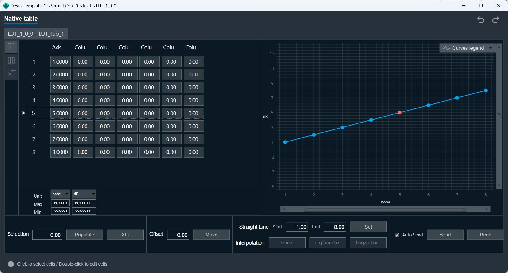
The number of elements corresponds to the number of columns. The table resolution on columns is configurable by modifying the first additional variable ‘Table Height’. Both the dependent and independent table values are configurable in the GTT. The x-axis (control-input) needs to be in ascending order and is configurable through the tuning tool.
Related Topics
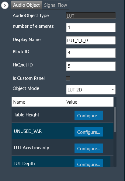
Lookup Table Properties
The table below describes the Lookup Table (LUT) audio object properties and functionality.
| Properties |
Description |
| Number of elements |
Enter the number of channels.
- Range: 1 to 254
- The default is set to 1.
|
| Display Name |
Display the name of the LUT audio object in the signal flow design. It can be changed based on the intended usage of the object. |
| Object Mode |
LUT works in two modes.
|
| Additional Parameters |
LUT has following additional parameters:
- Table Height
- Number of Control Inputs
- LUT Axis Linearity
- LUT Depth
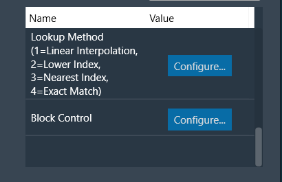
- Lookup Method
- Block Control
- Group
|
Mode
LUT audio object is used to manipulate some control input to pass to one or multiple connected objects. The object operates in two modes.
| Mode |
Description |
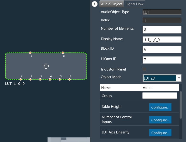
| LUT 2d |
In the 2D mode, the number of control inputs is configurable, and the number of outputs varies based on the number of elements and the number of control inputs selected.
In this mode, only one LUT table is allowed.
The objective of this LUT mode is to take in a control input, such as vehicle speed, and interpolate an output value, such as gain, based on values set during tuning. The output is then sent as input to other audio blocks.
Primary Success Scenario
- The user will tune the object and initialize from GTT.
- Capture input parameter.
- Perform a lookup operation to determine the output based on the selected lookup method.
- Output to the next object in the signal flow.
|
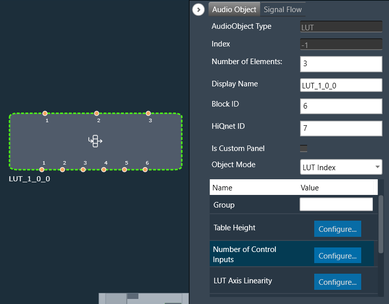
| LUT Index |
In the Index mode, along with the control inputs, there is a control input. This control input selects which ‘set’ of tables to use. Otherwise, the modes behave the same. The number of sets is configured by the additional variable ‘LUT Depth’. The maximum depth is 8.
In this mode, up to 8 LUT tables are allowed and can be configured in the additional config “LUT Depth”.
The objective of this mode of LUT operation is to determine the output given an indexed set of tables.
Primary Success Scenario
- The user will tune the object and initialize from GTT.
- Capture input parameters.
- Determine which indexed table to use.
- Perform a lookup operation to determine the output based on the selected lookup method.
- Output to the next object in the signal flow.
|
Additional Parameters
The following are additional parameters you can configure:
- Table Height
- Number of Control Inputs
- LUT Axis Linearity
- LUT Depth
- Lookup Method
- Block Control
- Group
| Parameter |
Description |
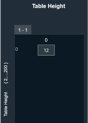
| Table Height |
This parameter corresponds to the size of each table in linear steps, which can be configured through an additional configuration variable.
- The default height of each table in linear steps is 2.
- The minimum height of each table in linear steps is 1.
- The maximum height of each table in linear steps is 200.
|
 |
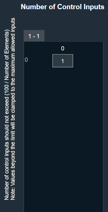
| Number of Control Inputs |
This parameter is used to configure the number of control inputs.
- The minimum number of control inputs is 1.
- The maximum range of control inputs is dependent on the number of elements and should not exceed (100 / Number of Elements). Values beyond the limit will result in clamping of the number of control inputs to the maximum allowed control inputs.
This enables LUT to send table values to different set of outputs independently using the same LUT table. This eliminates the need for duplication of LUT objects when the user wants to send table values to different audio objects independently using same table. |
 |
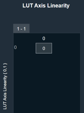
| LUT Axis Linearity |
This parameter is used to set the manipulation logic for interpolation through an additional configuration variable.
Manipulation logic
- 0: The Input axis may be unevenly spaced. This allows the user to specify table resolution where needed, but requires greater effort by the object, resulting in slower execution time.
- 1: The Object assumes evenly spaced values on the input axis in order to speed operations.
The default value of LUT Axis Linearity is 0.
|
 |
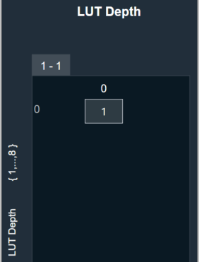
| LUT Depth |
This parameter is used to determine the depth of the table, which can be configured through an additional configuration variable.
- The default depth of each table in linear steps is 1.
- The minimum depth of each table in linear steps is 1.
- The maximum depth of each table in linear steps is 8.
|
 |
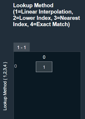
| Lookup Method |
This parameter supports one additional configuration of Lookup Method (linear interpolation/floored index/rounded index) for values on the output axis. This decides how output is computed for an input value that is between two given input axis values.
- Lookup Method = 1 (Linear interpolation): It provides standard linear interpolation of output between two axis points. This is the default type.
- Lookup Method = 2 (Lower Index): This is a Zero-hold or “previous” type of interpolation. It gives the nearest lower index, which is the floor value index.
For a given input, the control output is the value of the output that corresponds to the most previous input.
- Lookup Method = 3 (Nearest Index): This gives the nearest index, which is the rounded value index.
- Lookup Method = 4 (Exact Match): This outputs the row values only when the input exactly matches the axis.
|
 |
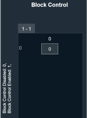
| Block Control |
This parameter supports additional configuration of Block Control, which can be enabled or disabled by selecting between Block Control Disabled (default) and Block Control Enabled.
If it is enabled, the control outputs are grouped into groups of the number of elements, and the number of outputs will then be equal to the number of control inputs. |
 |
| Group |
The Group feature allows organizing the LUT audio objects into different groups. When the native panel of any LUT audio object is opened, all the LUT audio objects with the same group name are displayed in that native panel.
If no LUT objects are assigned to any group, the native panel displays all the LUT audio objects. |
|
Tuning Parameters
The total number of tuning parameters depends on the LUT table height, table depth and number of elements. The number of elements is equal to the number of LUT table columns.
In the LUT table, there is also an additional column for ‘LUT Index’ mode, which stores the values of x-axis interpolation points. As a result, the total number of elements in the LUT’s parameter memory is as follows.
| Parameter |
Description |
Data Type |
Range |
Unit |
| m_Params for ‘LUT 2D’ mode |
Total tuning parameters = (NUM_ELEMENTS + 1) * Table Height |
Float |
-99999.0 to 99999.0 |
None |
| m_Params for ‘LUT Index’ mode |
Total tuning parameters = (NUM_ELEMENTS + 1) * Table Height * Table Depth |
Float |
-99999.0 to 99999.0 |
None |
Control Interface
There are one or two control input values stored in the state memory for LUT based on the mode selected.
The first corresponds to the value that needs to be converted to control output, and the second determines which table index to use for the lookup operation.
| Name |
Description |
Data Type |
Range |
Unit |
| m_states [0] |
Corresponds to the control input value that needs to be modified. |
Float |
-32768.0 to 32767.0 |
None |
| m_states [1] |
Determines which table index to use for interpolation. |
Float |
1.0 to 8.0 |
None |
The number of control outputs are equal to the number of control inputs * the number of elements. When block control is enabled, the control outputs are grouped into groups of the number of elements, and the number of outputs will then be equal to the number of control inputs.
Create LUT Object
- Load xAF DLL in GTT that supports LUT.
- Open the Signal Flow Designer.
- Drag and drop the LUT audio object into the Signal flow design view.
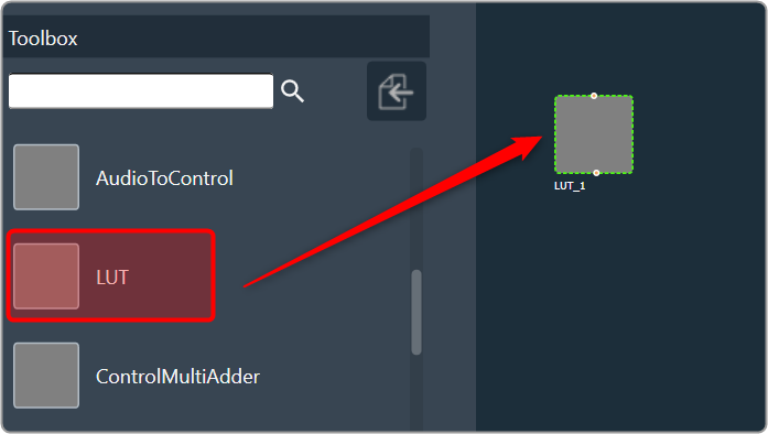
- Verify that the object is created with no error messages.
The properties and compare to these defaults.
The additional variables below are not actually object variables; they only belong to the GUI object and are not covered by this document. See Components of Signal Flow Designerfor more information.
| AudioObject Properties |
Additional Variables |
| number of elements |
1 |
Table Height |
2 |
| Object Mode |
LUT 2D |
Number of Control Inputs |
1 |
|
|
LUT Axis Linearity |
0 |
|
|
LUT Depth |
1 |
|
|
Lookup Method |
1 |
|
|
Block Control |
0 |
Create LUT Object in Mode 0 (LUT 2D)
- The object should already be in mode 0 (LUT 2D).
- Verify that by default, there is one control input and one control output.
- Change the number of elements to 3 and the number of control inputs to 2.
- Verify that the object now has 6 control outputs.
Create LUT Object in Mode 1 (LUT Index)
- Change the object mode to LUT Index.
- Verify that the object now has 3 control inputs (2 LUT inputs and 1 Index input).
- Change the number of elements to 3 and the number of control inputs to 2.
- Verify that the object now has 6 control outputs.
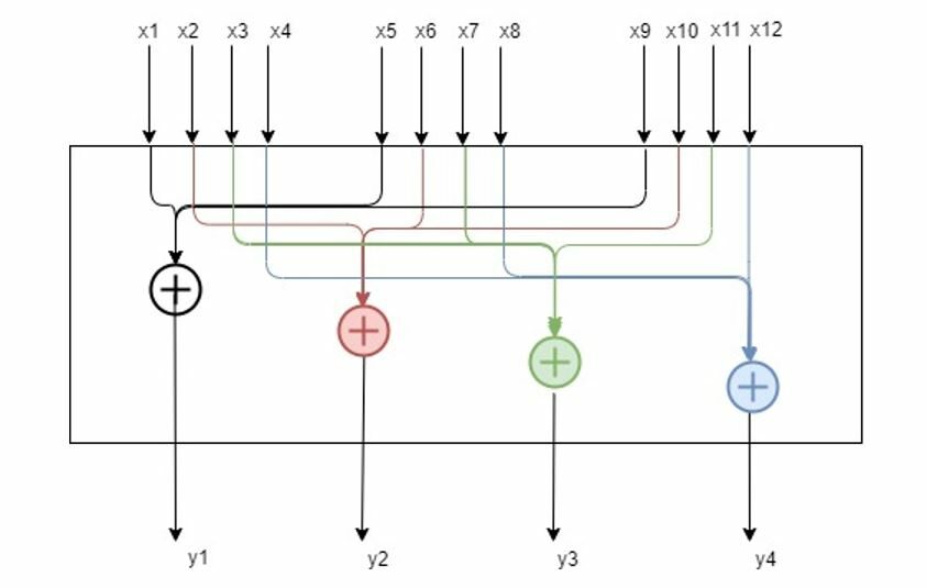
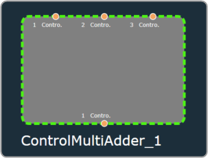 Example: If the numElements is 4, there will be 4 control outputs [y1, y2, y3 and y4] and 12 control inputs [x1 to x12]. The control outputs are computed as shown in the figure below.