Control IDS

The Control IDs are used to configure Custom Control IDs. Users can add, edit, export, and import Custom Control IDs data.

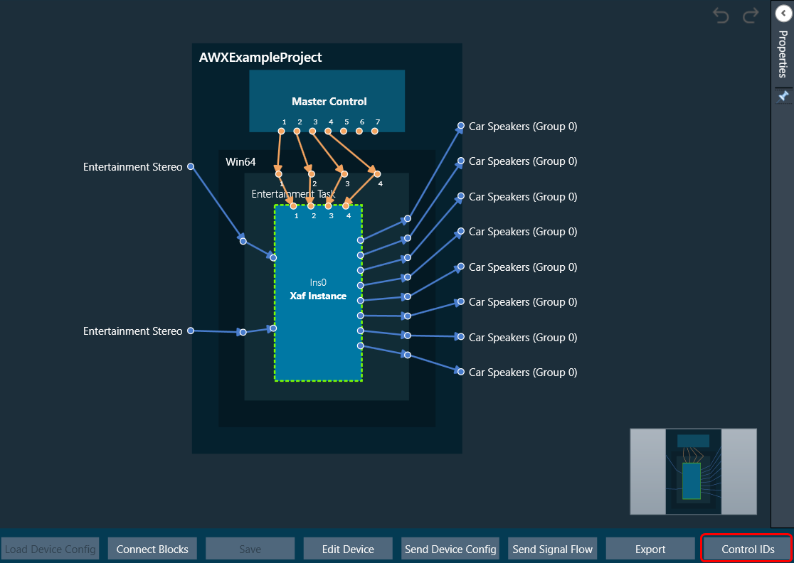
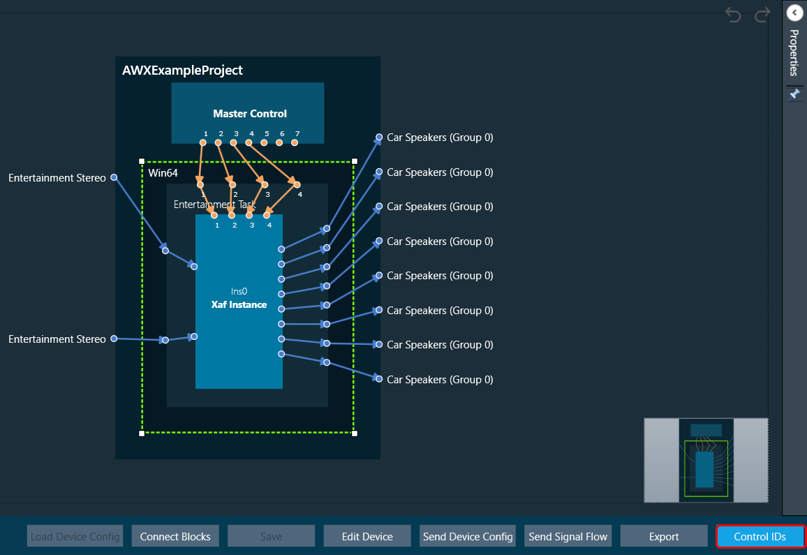
To open the Control IDs

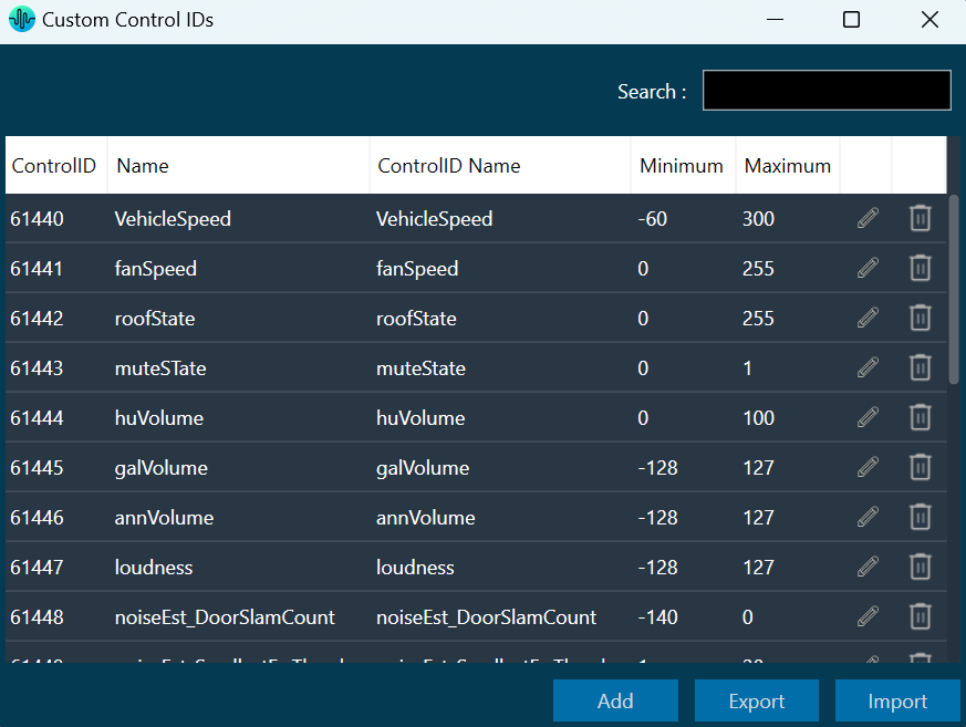
  1. On the Device View, click on the Control IDs. This opens the Custom Control IDs configuration window.
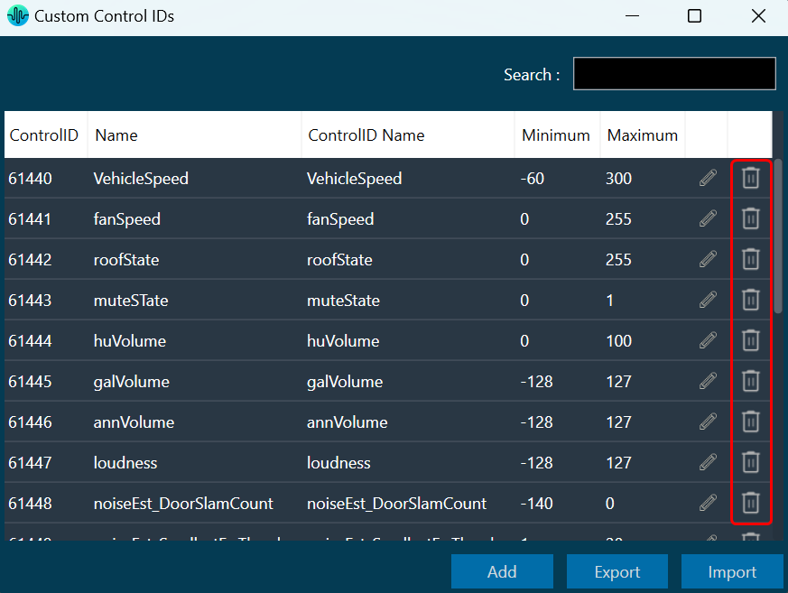
    The Custom Control IDs window shows all the custom control ID details.

To add the custom control ID

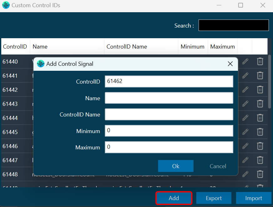
  1. On the Custom Control IDs panel, click on Add. This opens the Add Control Signal window, where the user can enter the details of the new custom control.

    You need to enter details in all fields. The maximum value of control should be greater than the minimum value. The Control ID range should be between 61440 to 65535.
  2. Click OK to save the custom control id details.

To edit the custom control ID

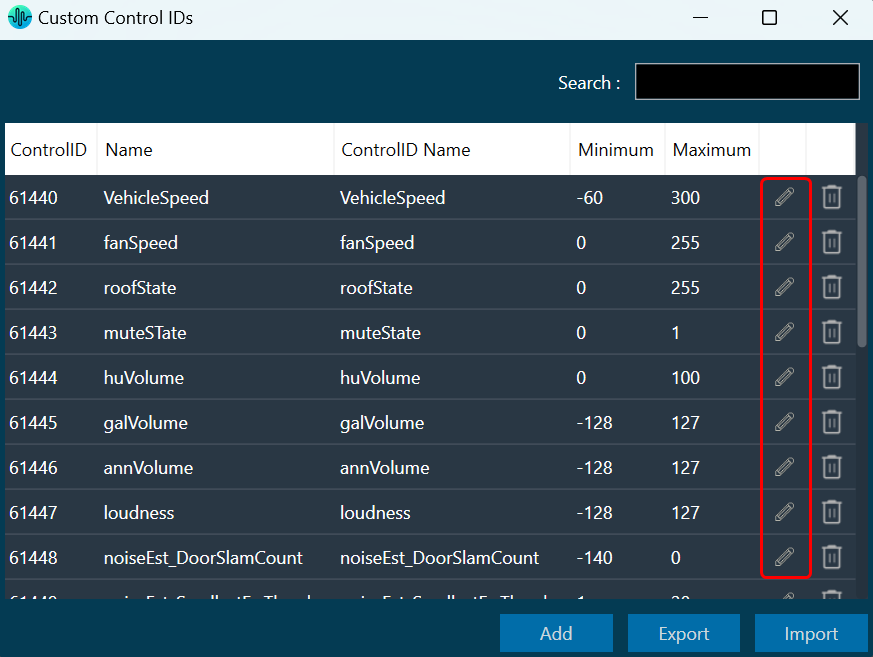
  1. On the Custom Control IDs panel, click on the Edit icon. This opens the Edit Control Signal window, where the you can update or change the custom control details.
  2. Click OK to update the custom control id details.

To delete the custom control ID

  1. On the Custom Control IDs panel, click on the Delete icon. This deletes custom control and also removes its associated data.

To export the custom control ID

Using the export option, all custom control data can be exported in the provided destination directory with the file extension *.csv.

  1. On the Custom Control IDs panel, click on Export. This opens the file directory.
  2. Navigate to the desired location and click Save to export the file.

To import the custom control ID

Using the import option, all the custom control data can be imported to GTT.

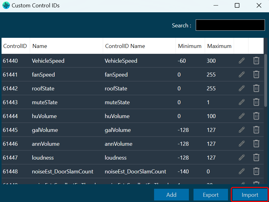
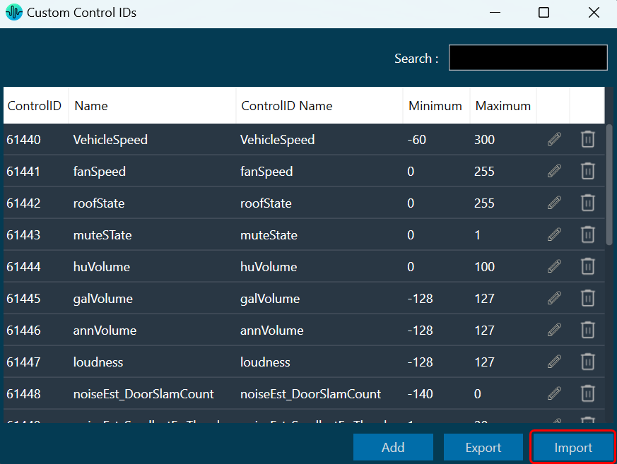
  1. On the Custom Control IDs panel, click on Import. This action opens the file directory.
  2. Navigate to the file location and click Open to import the file.

This action will import all the custom control pins from the file (with *.csv extension) in the custom control list.

A message will appear if the file is invalid or does not contain the required data.
Graphical user interface, text Description automatically generated

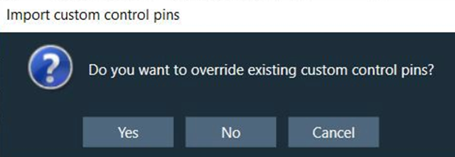
If GTT contains custom control IDs, it will ask for confirmation whether the user wants to overwrite them.

An error message will be displayed if the import file contains duplicate control IDs.
Graphical user interface, application, website Description automatically generated

Panel Designer Overview

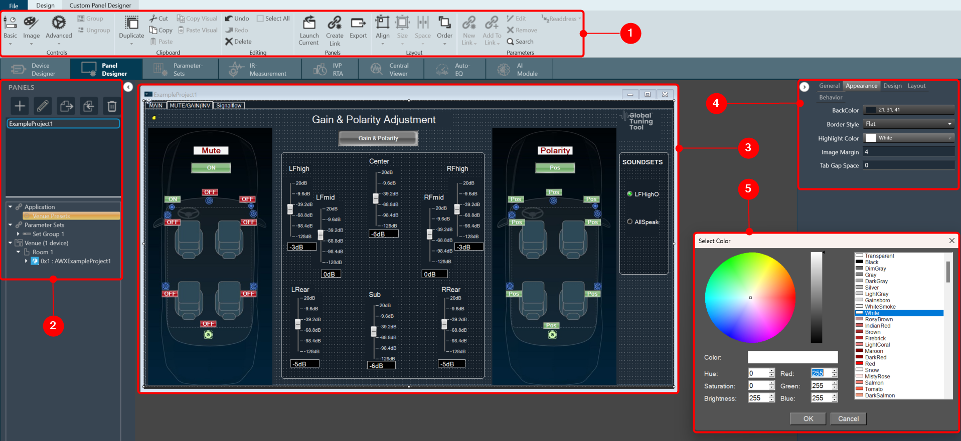
The Panel Designer comprises of various features, that offer you a thoughtfully designed, clean, and easy-to-use workspace. Using Panel Designer, you can quickly create a custom panel with all the elements you need and link the panel with a desired audio object. Let us have a look at some of the components of the Panel Designer workspace.

  1. Panel Designer Ribbon: The Panel Designer ribbon contains tools for designing and editing the custom panel. The ribbon is divided into the following groups: Tools, Current Panel, Controls, Clipboard, Editing, Layout, and Parameters.
    The Panel Designer ribbon contains tool for designing and editing the custom panel.

    The Panel Designer ribbon comprises the following group.

  2. Panels View: The Panels view in Panel Designer displays all the custom panels and allows you to create, delete and import the custom panels. In addition, you can access the Venue Explorer to view available Device(s), Applications, and Parameter Sets.
  3. Custom Panel Properties View: The Properties view displays the properties of each component used to design the custom Panel and also allows you to customize the Panel to meet your needs. The Properties view is displayed on the right-hand side of the screen.
  4. Designer Workspace: You can use various tools available in the Toolbox to create a custom panel in the Designer workspace.
  5. Editor Windows: In the Properties view you can customize the Panel using various editour windows. These editour windows are mapped with corresponding properties.

Device Operations

This section explains the device operation features available at the bottom of the Device Designer workspace.

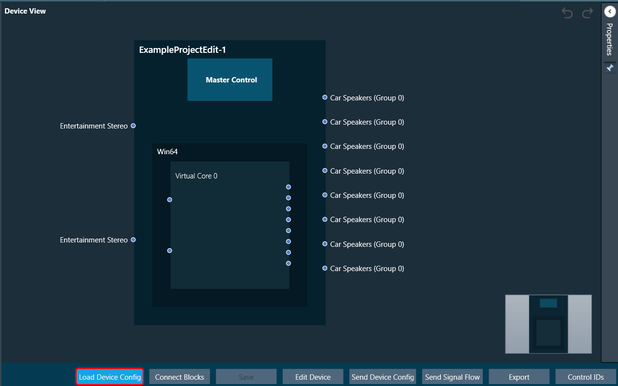
Load Device Config


When there are no core objects in the cores, the Load Device Config option is enabled. The Physical Cores and Virtual Cores (available within a Physical Core) as well as their connection points that were fetched from the target during device discovery are visible after the device has been loaded. Since they are read from the device, the number of virtual cores and their connection points cannot be changed.
You can connect core objects by dragging them onto the virtual cores. Alternatively, you can select the “Load Device Config” option, which will read the target’s device routing information as well as the layout and routing between core objects and display it on the GUI.

In the device view, a property section has been added to display and change the properties of chosen Core or Core Objects. When the virtual core or core object is selected, their respective properties are shown on the screen.

If you don’t clear the device view first, you won’t be able to save or access SFD.

The device identification feature is enabled for audio libraries version 13 and higher.

Connect Blocks


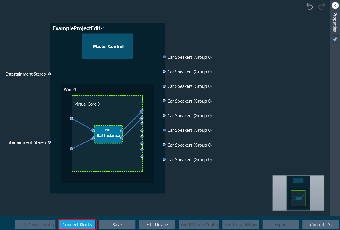
You can auto-connect selected devices, cores, and core objects using Connect Blocks.

Choose at least two cores and click Connect Blocks.

You can auto-connect the following components.

  • Device – Virtual Core(s)
  • Virtual Core(s) – Virtual Core(s)
  • Virtual Core – Core Objects (within selected Virtual Core)
  • Core Object(s) (within same Virtual Core)

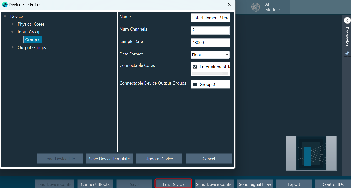
Edit Device


In Device File Editor you can modify the device configuration, then perform “Save Device Template” or “Update Device” operation.

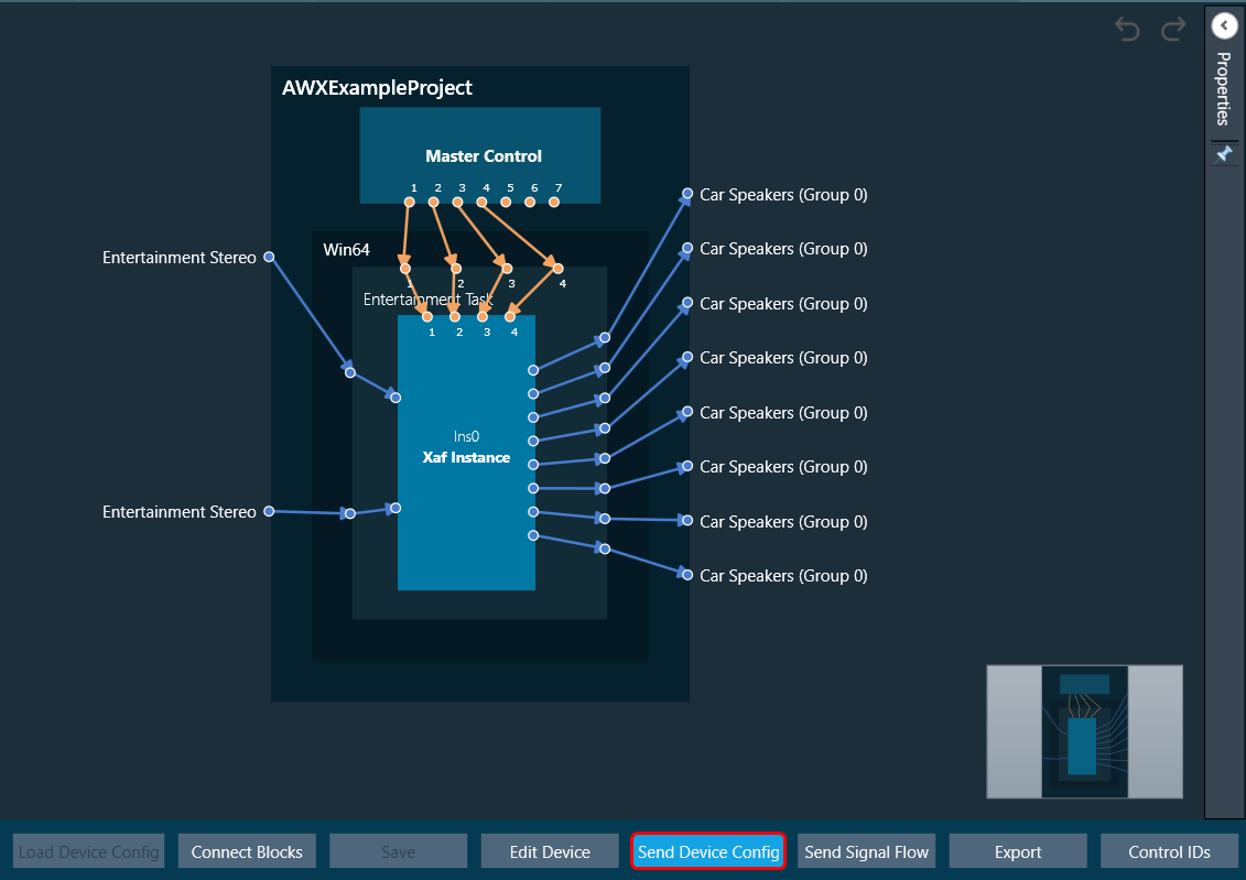
Send Device Config


You can create your own configuration and write this configuration to the target device. The Send Device Config option sends the device configuration (Core Objects, Device Routing, and Virtual Core routing) to the target device.
Before sending the device configuration, all the input and output connection points of the core objects must be connected. If any of the pins are not connected, an error message is displayed.

The Device view (number of Cores, Physical Cores, Connection points, Sample Rate, and Block Length) inside GTT and the data inside the Device. The flash file on the target should match before Sending the Device configuration. If the data doesn’t match, then the below transmission error is seen

The data in the device view (number of cores, physical cores, connection points, sample rate, and block length) and the data in the device. The flash file on the target device should match before the device configuration is sent. If the data doesn’t match, you will see the transmission error.
Graphical user interface, text, application Description automatically generated

If any changes are made to the configuration, the send device config must be completed before sending the signal flow.

The device identification feature is enabled for audio libraries version 13 and higher.

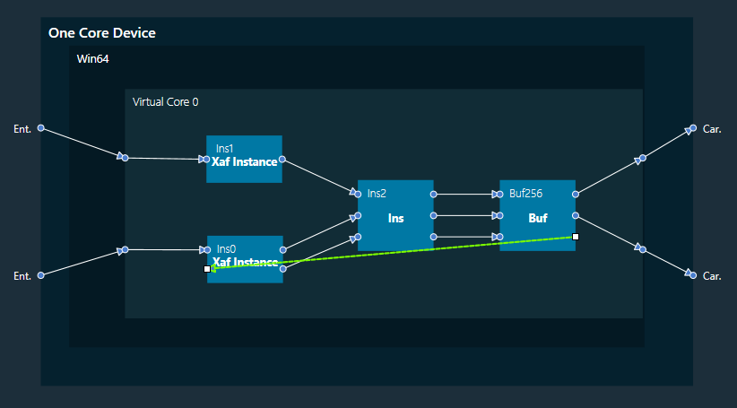
Feedback Loop

In the device view, feedback connections are allowed. You can connect the output of any core object as input to any other core object.

Core object Id defines the order of execution of core objects. Execution order of any core object depends on the IO dependency. IO side dependency is not considered when there are feedback loops.

Self-loop is not supported as feedback.

In the image, connection highlighted in green color is a feedback connection.

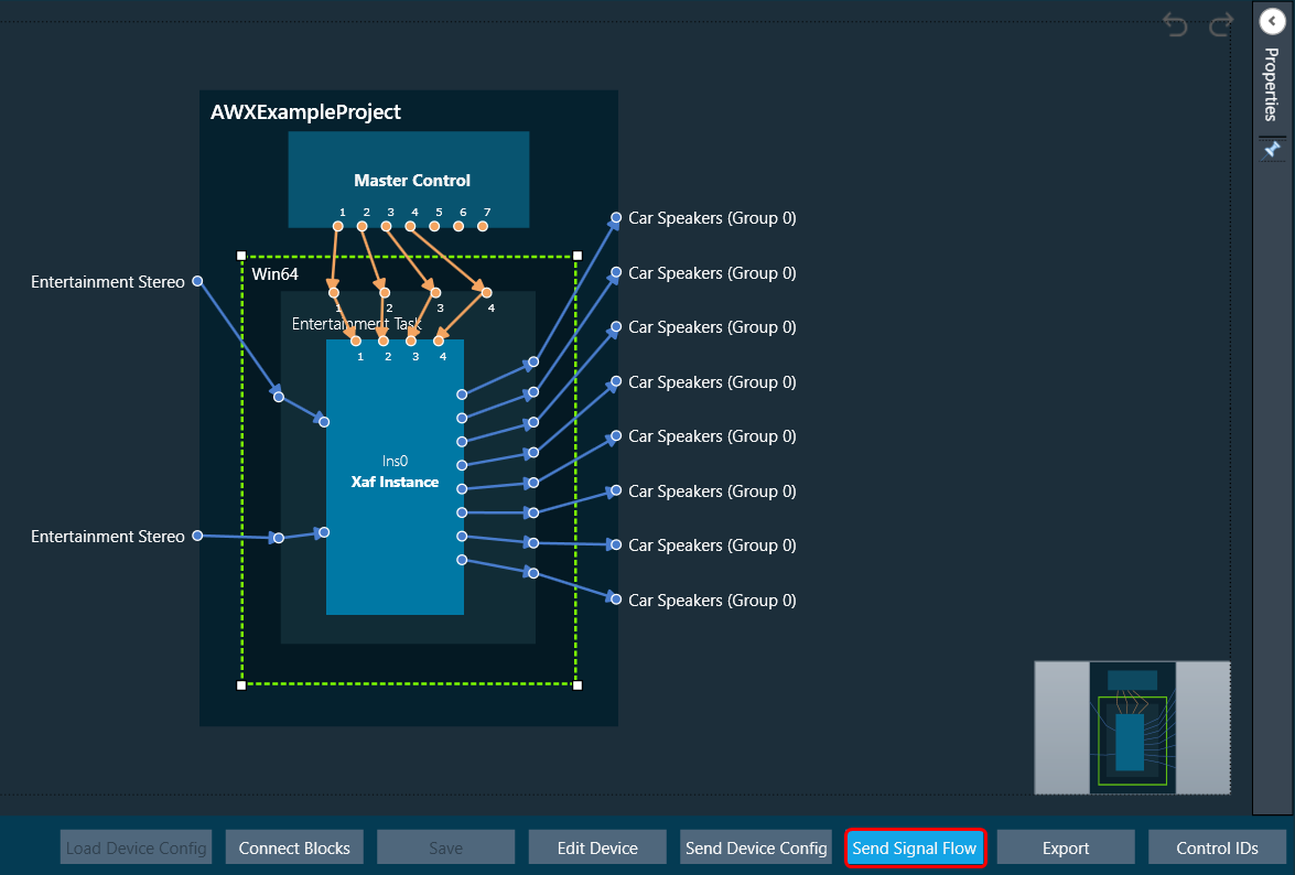
Send Signal Flow


The Send Signal Flow option sends the configuration of the signal flow design to the target device. You can also use this to test how the target device responds to specific test signals. In a test scenario, you can configure specific test signals and send them to the amplifier.

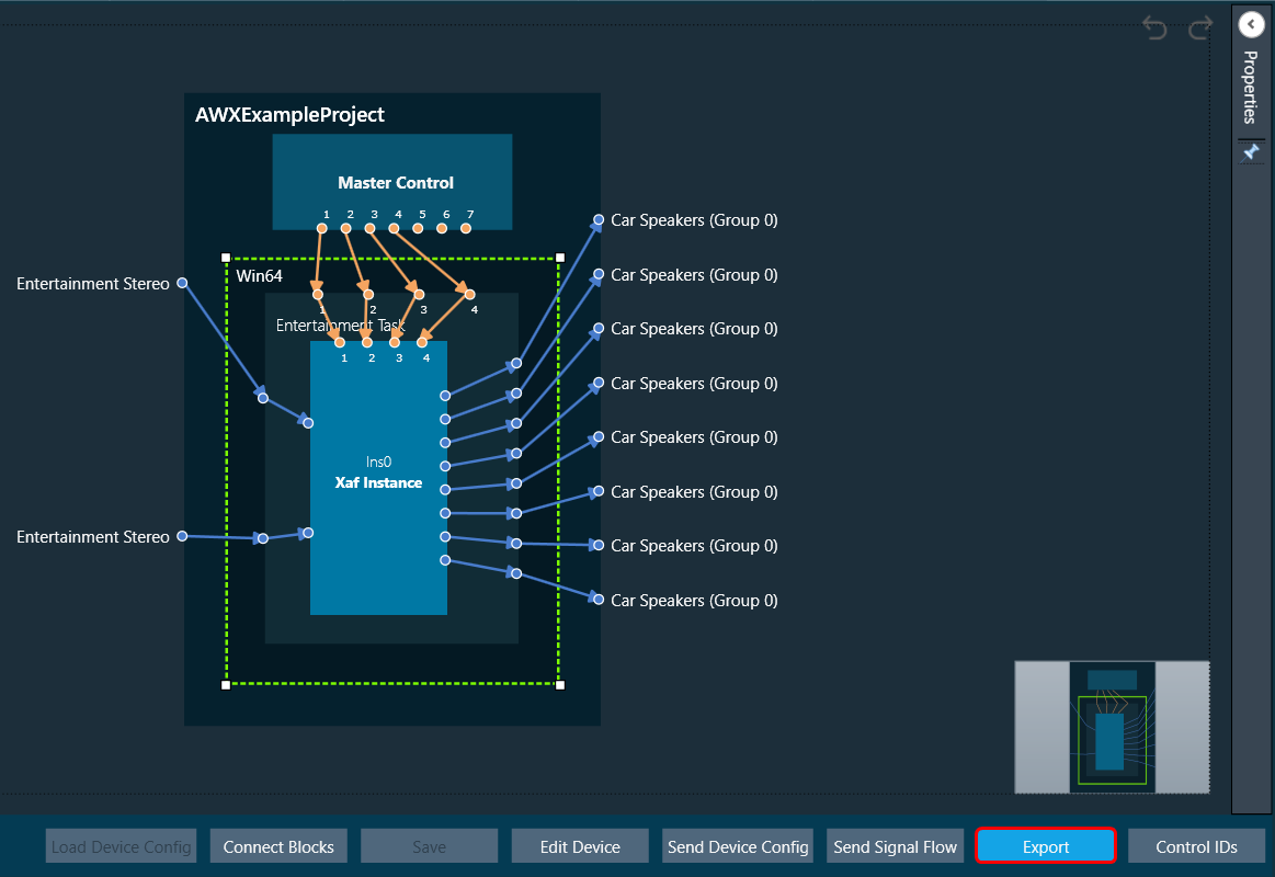
Export


Using the Export option in the device view, you can export the device configuration data and the signal flow design details.

*.Core files would be created for each Virtual Core available in the device. One *.route file will be created for Device routing data. One .mcd file will be generated for master control data and one .SFD file will be generated per instance per core.

  • One core file per virtual core in the signal flow.
  • The core objects within the virtual core.
  • The routing within those objects.
  • The destination of the output pins of the virtual core.
  • One signal flow file per xAF instance.
  • This is the same legacy file.
  • One input device routing file.
  • This basically describes how the device input buffers are connected to the virtual cores and/or the device outputs.

Control IDs


The Control IDs are used to configure Custom Control IDs. You can add, edit, export, and import Custom Control IDs data. For more details, refer to Configure Control IDS.

Device View

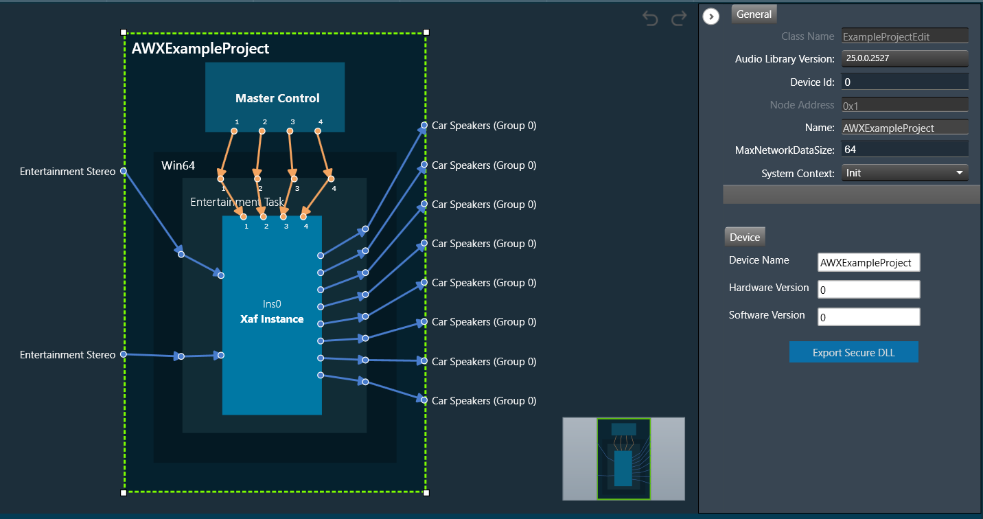
The Device View is used to view and modify detailed information and settings for a specific device. Double-click on the desired device from the list to open a device template in the Device View.

If the core object is not supported in the core type of physical core, then the core object will be shown in red, and the user has to correct the device view before saving the flow.

Under Device view following topics are discussed:

Properties Panel

Graphical user interface, application, chat or text message Description automatically generated

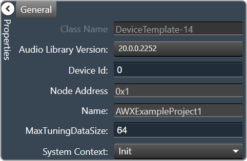
  • Class Name: Display type of device and this property is read-only,
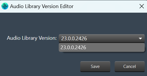
  • Audio Library Version: Display the audio library version used in the selected device. You can change the audio library version. On the property panel, click on the audio library version, select the desired audio library version, and click save.

    If a device has a signal flow with audio objects created in an older version, compatible audio objects will upgrade automatically. Non-compatible audio objects in Signal Flow Designer will be highlighted in blue or displayed as a warning in the compiler; these audio objects can be upgraded using the audio object context menu.In the following cases device association with a dll cannot be changed.

    • If a device’s signal flow is open.
    • If you have a monitoring window open, such as a streaming or profiler window.

    A change in dll association for one device has no effect on other device instances.

  • Device Id: Enter the ID of the selected device. Make sure the device ID should be unique.
  • Node Address: The Node address of the selected device. Each device has a unique node address assigned to it.
  • Name: Name of the device.
  • MaxTuningDataSize: Maximum tuning data.
  • System Context: Set the system context Init or Runtime.

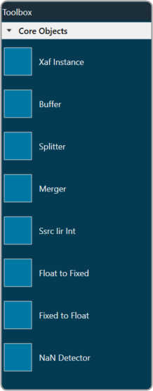
Core Objects Toolbox

The Core Object Toolbox contains the core objects that were retrieved from the xAF dll. The objects that can be used within the core to create the device signal flow are called core objects. Each core object has its own purpose and solves parametric issues that block routing within the core.

The Core Objects are classes that are part of the Audio Core (virtual core) class and operate at a higher level than audio objects. The audio processing class itself is a core object.
The relationship between core objects and the audio core is similar to that of audio objects and the audio Processing class.

Static Metadata

All core objects describe their features, attributes and capabilities to the tuning tool through metadata that are used in signal flow design. There are two attributes that are conveyed through the metadata.

  • List of supported core types — if the list is empty, it indicates that there are no restrictions, and the core object is supported on all core types.

An yellow border on the core object indicates that there is a restriction on the core type.  User can mouse hover of the core object to see the supported core types.

  • Version — comprising major and minor fields.

Core objects


The following is the list of core objects available:

The execution order (or index) of the core object is displayed by Core Object Id. Routing determines the order in which core objects are executed within a core. The core objects that are connected to the core input will be executed first, and the core objects that are connected to the root object after that will be given the next execution order.

The device identification feature is enabled for audio libraries version 13 and higher.

Xaf Instance

The Xaf Instance is the core object inside which the signal flow for that instance can be created.
Graphical user interface, text Description automatically generated

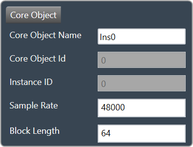
  • Core Object Id (execution order of core-object within core) and Instance Id (index of xAF instance within core, based on execution order) will be displayed as read-only fields.
  • The sample rate and block length of the instance will control signal flow within the instance. You can change the sample rate and block length of the instance in the properties section.
    Graphical user interface, application Description automatically generated

Further information on signal flow creation is available in the GTT Signal Flow Designer guide.

Buffer

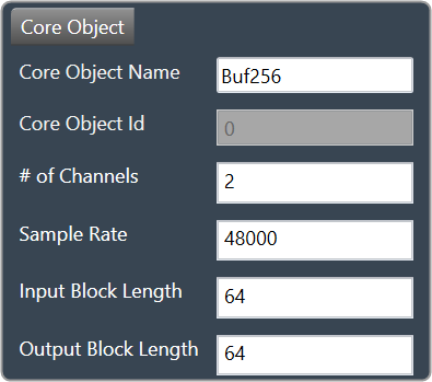
Buffer core object is used to convert the input block length into the required output block length. The buffer core object has an equal number of input and output channels. It can be used as a pass through core object OR it can be used to, as its name suggests, buffer samples from the input to the output. The object does not change the sample rate (it is the same at the input and the output).
Text Description automatically generated with low confidence

If you want to connect two core objects with different block lengths, you can use a buffer core object. As a result, the input block length will be the Block Length of the first core object, and the output block length should be the Block Length of the other core object.
Graphical user interface, application Description automatically generated

It can be configured as follows:

  • If the input block length is equal to the output block length, then it behaves as a pass through object (so you could have an audio core with a buffer object to connect the core input to the output)
  • Input and output block lengths must be an integer multiple of each other
  • When input and output block lengths are not equal, the object handles taking in input at a lower block length and outputting it at a higher one and vice versa. For example, it facilitates the connection of an object at block length 32 to an object at block length 64

Introducing this object into your signal flow for any case but pass through WILL result in latency at the output.

Splitter

Splitter core object is used to convert one input to multiple outputs of the same sample rate and block length.
Text Description automatically generated

  • This core object always has a single input.
  • In order to make routing from any core object to the splitter both the source core object and splitter core objects sample rate and block length should match.
  • The number of output channels for the splitter is configurable.
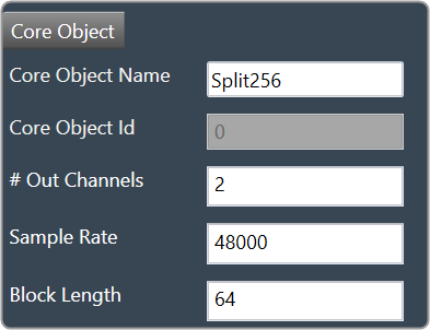
    Graphical user interface, text, application Description automatically generated

It is not to be confused with the Splitter audio object.

This object operates in parallel to an xAF instance, NOT within it.

Merger

Merger core object is used to merge multiple inputs into a single output of the same block length and sample rate.
Text Description automatically generated

  • This core object always has a single output.
  • In order to make routing from any core object to merger both the source core object and merger core objects sample rate and block length should match.
  • The number of input channels for the merger is configurable.
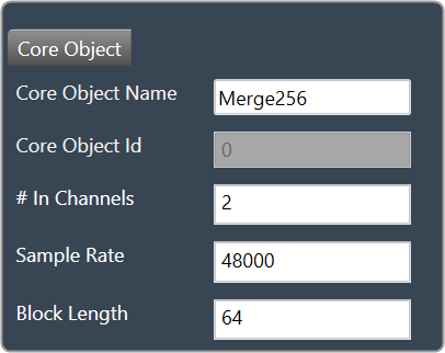
    Graphical user interface, application Description automatically generated

It is not to be confused with the Merger audio object.

This object operates in parallel to an xAF instance, NOT within it.

Ssrc lir Int

Synchronous Sample Rate Converter (SSRC) is used to convert the input sample rate to the required output sample rate.
SSRC core object can operate within an audio core. Currently, there is one implementation of SRCs in AudioworX.
Text Description automatically generated

Two options are provided to convert the sample rate. Both these options are mutually exclusive.
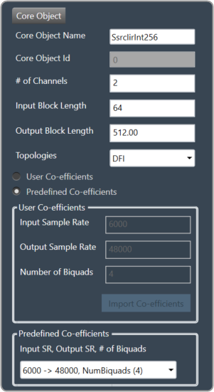
Graphical user interface Description automatically generated

IIR Integer Multiple SSRC

This core object implements a synchronous sample rate converter whose input sample rate / input block length and output sample rate / output block length are integer multiple of each others. This is also an infinite impulse response implementation (IIR).

The object operates in one of 2 modes:

  • User Coefficients mode
  • Predefined Coefficients mode

Before we get into the details, there are some common configuration parameters between the two.

  • The input block length needs to be set by the user.
  • The Biquad filter topology. Currently, 2 topologies are exposed.
    • Direct Form I
    • Direct Form II

User Coefficients mode: In this mode, the user has to provide the input and output sample rate. Input and output sample rates should not be equal. The Number of Biquads field is read-only.
The user has to import the coefficients by clicking on the button “Import Co-efficients”. Based on the number of coefficients in the file, the Number of Biquads is updated.

Validations for User Coefficients mode: The Input and Output sample rates cannot be the same. Validation is shown when the same values are entered.
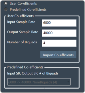
A screenshot of a computer Description automatically generated with medium confidence

After adding a new “Ssrc lir Int” object and selecting “User Coefficients Mode”, if the coefficients are not imported, the following message will be displayed on various operations such as “Save”, “Edit Device”, “Copy Core Objects” and “Paste Core Objects”. After importing coefficients, the user can perform the required operation.
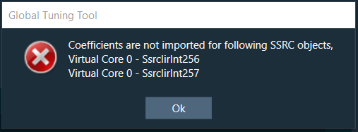
Graphical user interface, text, application Description automatically generated

Predefined Coefficients mode: In this mode, the xAF dll is used to read the input sample rate, output sample rate, and the number of biquads. When a value in the combo box is selected, the xAF dll is also used to fetch the corresponding coefficients.

Biquad Co-efficient has to be re-imported whenever the mode is switched between Predefined Co- efficient mode to User Co-efficient mode.
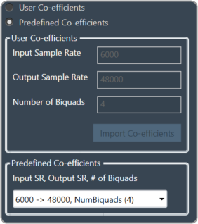
A screenshot of a computer Description automatically generated with medium confidence

For these pre-defined coefficients, the quality measures are as follows:

  • Signal to noise ratio: 80 dB
  • Total harmonic distortion: 2e-3f
  • Spurious free dynamic Range: 59 dB
  • Total harmonic distortion plus noise: -60 dB
  • Frequency response flatness: 3 dB

Output block length (Displayed as a read-only field) = (Output sample rate /Input sample rate) * Input block length.

Float to Fixed

Float to Fixed core object accepts audio buffers that are in floating point format and outputs buffers that are in fixed point format (16-bit, 24-bit, 32-bit etc).
Graphical user interface, text Description automatically generated

  • # of Channels is configurable. No of Input channels = No of Output channels
  • The user can configure the scalar value to indicate what fixed point format is required. This scalar value is multiplied by the floating point input samples to convert them to fixed point.
    For example, to convert from float to 32 bit fixed point, this scalar value must be:
    (1 << (32-1) – 1) = 2,147,483,647
  • In order to make routing from any core object to Float2Fixed object both the source core object and Float2Fixed core objects sample rate and block length should match.

The Float To Fixed core object is enabled for audio libraries version 16 and greater.
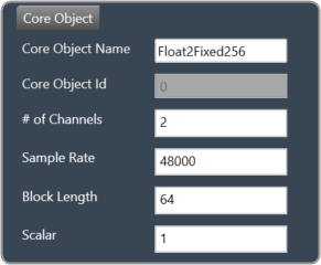
Graphical user interface, application Description automatically generated

Fixed to Float

Fixed to Float core object accepts audio buffers that are in fixed point format (16-bit, 24-bit, 32-bit, etc) and outputs buffers that are in floating point format.
Graphical user interface, text Description automatically generated

  • # of Channels is configurable. No of Input channels = No of Output channels.
  • The user can configure the scalar value to suit the fixed point format of the input samples. The reciprocal of this scalar value is multiplied by the fixed point input samples to convert them to floating point.
    For example, to convert from 32 bit fixed point to float, this scalar value must be:
    (1 << (32-1) – 1) = 2,147,483,647
  • In order to make routing from any core object to Fixed2Float object both the source core object and Fixed2Float core objects sample rate and block length should match.

The Fixed To Float core object is enabled for audio libraries version 16 and greater.
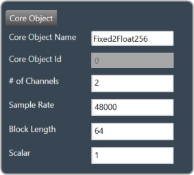
Graphical user interface, application Description automatically generated

Nan Detector

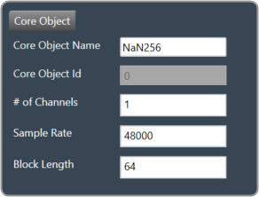
The NaN (Not a Number) detector core object detects NaN from input samples and informs the platform using an xTP command if NaN is found. The xTP command will inform about the core id, core object instance id and channel index, so that platform can react accordingly by muting or resetting states. The input samples are copied to the output without doing any other processing. The number of output channel(s) is always same as the number of input channel(s).
Graphical user interface, text Description automatically generated

  • # of Channels is configurable. No of Input channels = No of Output channels.
  • Block length and Sample rate are configurable.
  • The number of input channels is user configurable and ranges from 1 to 255.
  • The core objects’ block length and sampling rate are the same at both the input and output sides.
  • Block length is configurable in the range of 4 to 4096 samples.
  • Sample rate is configurable in the range of 8 kHz to 192 kHz.

In order to make routing from any core object to NaN Detector, both the source core object and NaN Detector core objects sample rate and block length should match.

The NaN Detector core object is enabled for audio libraries version 19 and greater.
A screenshot of a computer Description automatically generated with medium confidence

Core Objects Validation

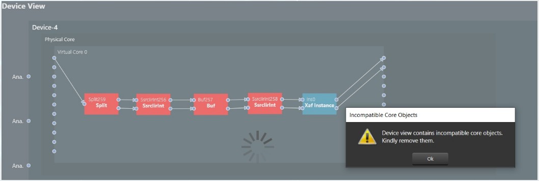
When the GTT is loaded with a version of the xAF library lower than 13. If a user tries to open a device view that contains core objects other than an XAF instance, they will see the following error message.
Graphical user interface, diagram Description automatically generated

Aside from the Xaf instance, every other core object will be red.
Graphical user interface Description automatically generated

MIPS

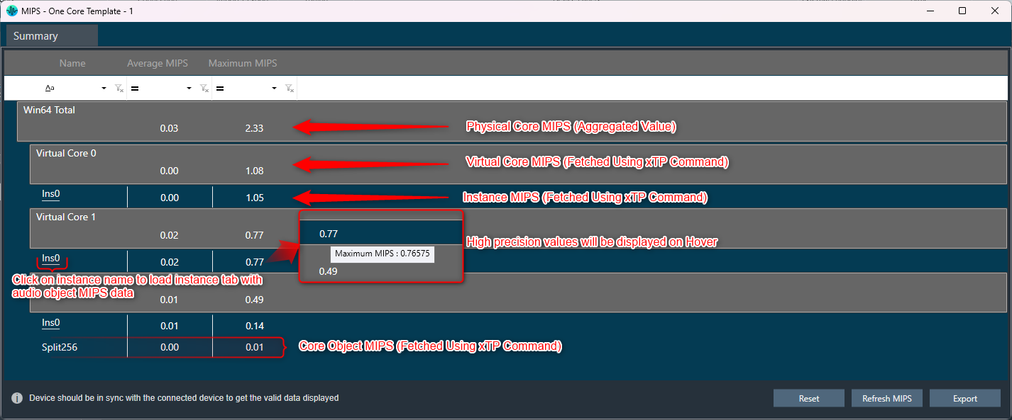
The MIPS window presents the CPU load of cores, core objects and audio objects of the connected device.

MIPS profiling data is fetched from the device (hardware) using xTP Commands and the user can optimize signal flow based on this information.

MIPS window is enabled only when the device xAF dll version is 18.x.x.xxx or higher.

Signal flow should be flashed before launching MIPS.

MIPS profiling data of non-xAF instance core objects (Buffer,Splitter…etc) is available only from X release(24.x.x.xxxx) audio library onwards.

Launch MIPS Profiling

Steps to launch MIPS profiling:

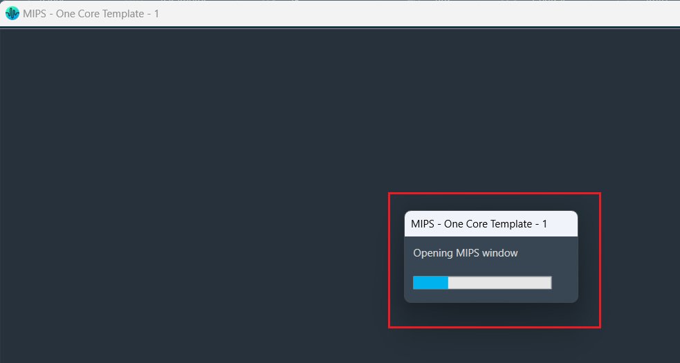
  1. Select the device node and click MIPS. This opens the MIPS window for the selected device.
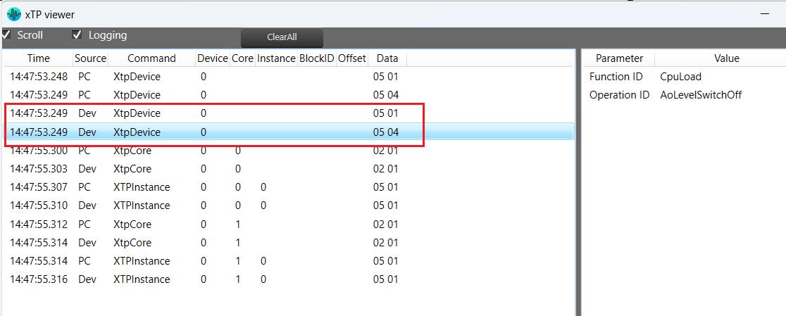
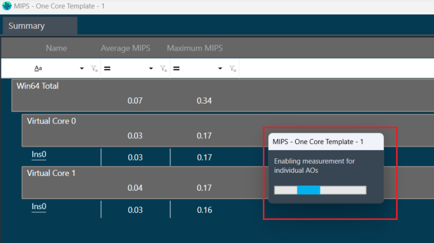
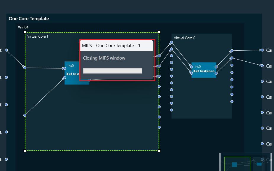
    MIPS measurement on (0x64000501) and Audio Object level MIPS measurement off command (0x64000504) will be sent while opening the MIPS window and a progress window will be seen as per the below screenshot.

The following command will be displayed in the xTP Log Viewer.

Summary Tab

  • Present virtual core and core object MIPS data (Average MIPS and Maximum MIPS) retrieved from the device using the xTP Command.
  • MIPS data displayed on the physical core are the aggregated values of its virtual cores.
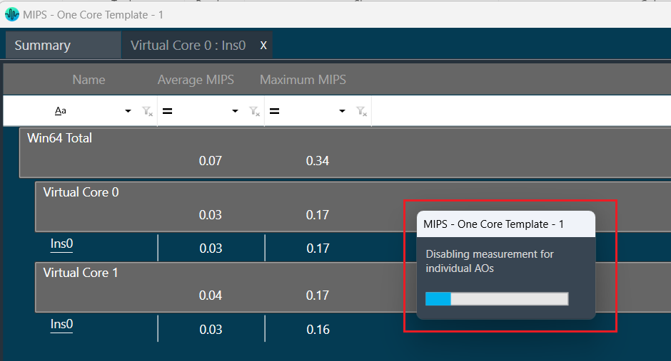
  • Audio Object level MIPS measurement off command (0x64000504) will be sent while switching to the Summary tab from the Instance tab and a progress window will be seen as per the below screenshot.

Below command will be seen in xTP Log Viewer.

Instance Tabs

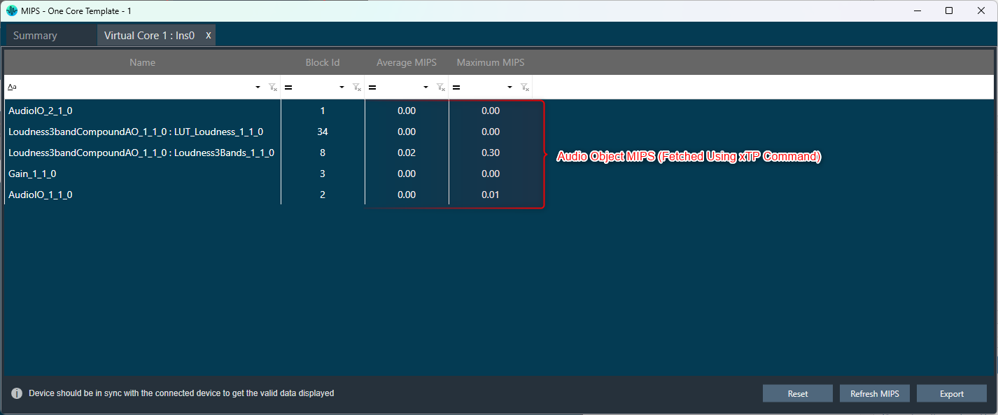
  • A new tab corresponding to the selected instance will be loaded, displaying audio-object MIPS data retrieved via the xTP Command.
  • Inner audio objects will be displayed alongside compound audio objects for compound audio objects.
  • Audio Object level MIPS measurement on command (0x64000503) will be sent while opening a new Instance tab or switching to the Instance tab from the Summary tab and a progress window will be seen as per the below screenshot.

Below command will be seen in xTP Log Viewer.

Reset

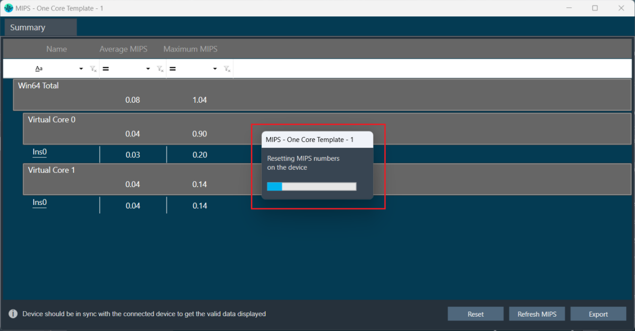
When you click the Reset option, the MIPS number for the device will get reset for the selected tab and Reset command (0x64000500) will be sent and a progress window will be displayed as per the below screenshot.

Below command will be seen in xTP Log Viewer.

Refresh MIPS: When you click the Refresh Mips option, the MIPS data for the current tab will be refreshed.

Export to CSV: When you select the Export option, the Mips data for the current tab will be exported to a CSV file. The CSV format is shown below.

Summary Tab
Instance Tab

Closing MIPS Window: When you click on cross (x) to close the MIPS window, the MIPS measurement off command (0x64000502) will be sent and a progress window will be displayed as per the below screenshot.

Below command will be seen in xTP Log Viewer.

Link Window

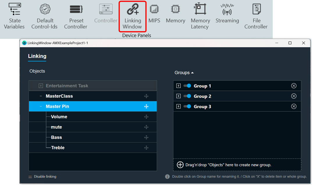
The Linking Window is designed to assist you by reducing the number of audio parameter configurations. It enables you to organize the filters and channels. When you set one item in a group, the remaining items in the group will have the same value.

By default, all the groups link are enabled. If you want to disable the specific group link, click on the toggle button to disable it.  GTT will store the group linking status in project file.

If you want to disable all the groups link, select the Disable Linking checkbox.

Create a New Group

Steps to create a new group:

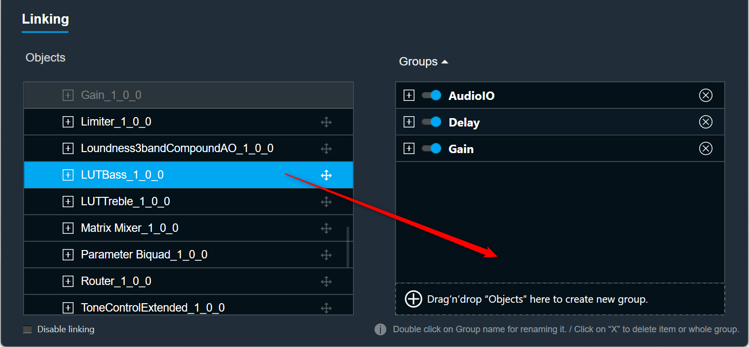
  1. Open Linking Window, expand the task, and drag-drop the object to the right-side section under Groups. A new group is created, expand the new group. Under the new group, you can view the added object.

Renaming Groups: Double-click on a group name to rename it.

Only groups can be renamed; Audio objects cannot be renamed.

Removing Objects: Click on the remove icon to remove the object. This will also delete all child objects.

Removing Groups: Click the remove icon to the right of the group. This will also delete all child objects.

Add Object to Existing Group

Steps to add object to an existing group:

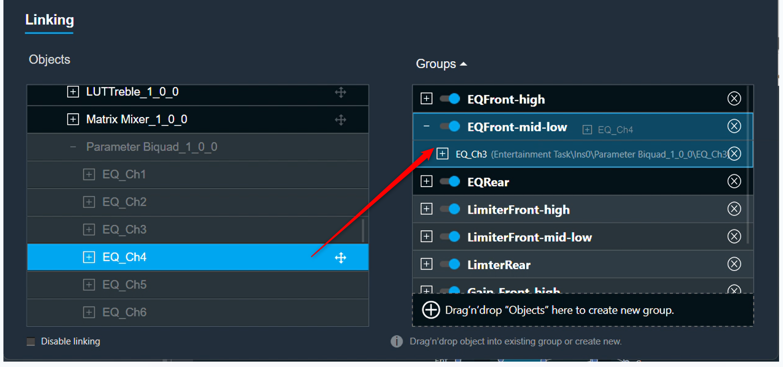
  1. Open Linking Window, expand the task, and drag-drop the object to the right-side section under target group. A new group is created, expand the new group. Under the new group, you can view the added object.

If an object cannot be added to a specific group, the color of that group will change to grey.

If the object is added to the group, the color of the group will change to blue.

Linking Rules

  • Each of the audio objects can be part of only one group.
  • If a child audio object is part of a group, the parent element cannot be part of that group.
  • Groups can contain only one type of audio object. For example, you cannot link a Biquad with a Delay. Each group can contain more than one AO.
  • Objects in groups are linked according to their order. For example, if you link two EQ channels, the first Biquad from the first channel will be linked with the first Biquad from the second channel.
  • Changing links is done live. You do not need to close the window for the changes to be working.

Controller

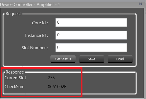
The controller window is used to send instance commands.

The controller feature is enabled only when the device xAF dll version is lower than 18.x.x.xxx.

Steps to setup controller:

  1. Enter a valid Core Id and Instance Id and click on Get Status to get the current available slot of the device. The response from the device will be displayed in the Response section.
  2. Click Save to save the current instance data on the device to the memory slot entered.
  3. Click Load to load the data from the memory slot to the device RAM.

If there is any error in the device connection or if any invalid Core Id and/or Instance Id were entered, the error message “Request failed!!!! Please make sure […]” will be displayed.

Configuring Preset Controller

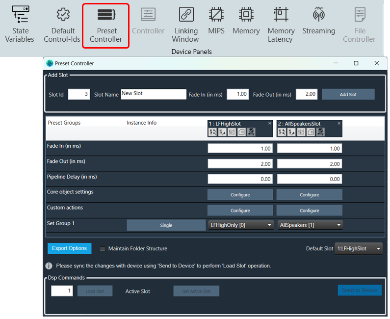
The preset controller is the central place for managing and organizing how you will load presets in your signal flow.  It also contains other related features such as creating .set files, storing sets, and recalling sets of parameter sets available.
A “Slot” is a group of parameters set one level above. You can create multiple such slots and do any actions like create set files, store , recall etc.
In addition to GTT functionalities, it is also possible to send Xtp commands to device. There are XTP commands to send slot map and Load the slot on to device. You need to export all .set files and manually flash on to the amp.

To know more about  the Preset Controller functionality, refer to below topics.

Limitations in Preset Controller

  • After the set map is configured, if parameter sets are deleted, a generic sets window should be reopened to see the changes.
  • Generic sets window can be opened only one at a time. If a new window has to be opened for a new device, the currently opened window will be automatically closed (changes made will be retained).
  • Parameter sets are project specific. Generic sets are device-specific.
  • Only basic validations are done. Illegal values are yet to be handled. Ex: Entering a string value for fade in –out is considered illegal and will not be handled.
  • Signal flow and presets saved on the device should be in sync.
  • The slot map and set files export is offline. The user shall make sure that these files are in sync with GTT for better visualization.
  • All the presets configuration, slot map, and preset data are sent together in “Send To Device”. There is no option to send these data individually.
  • For any changes in presets or maps, the user is expected to send all data (config, map, and presets).

Virtual device naming conventions. The set files should always follow the “preset [preset id]” naming convention. Example preset0, preset1, etc. when checkbox “Maintain Folder Structure” is unchecked.

When exporting the slot map file for Virtual Device usage, the name should always be sect262144.flash.

If set groups overlap for a given audio object, the one loaded last will override the first.  The order is not guaranteed so it is not recommended to do this.