Default Control-Ids

The Configure Default Controls option allows you to specify which default control ids should appear in the “Control In” control list.

To Configure the Configure Default Controls:

  1. Click on Default Control-Ids. This opens the Configure Default Controls window.
    If no configuration is defined, all Control IDs are selected in the Configure Default Controls window.

    In the Configure Default Controls window, you can select or unselect control IDs.

    You cannot deselect the Control ID used in the Signal Flow Designer.

  2. Select or deselect the required control Ids and click Save to update the configuration.

Use the search text box to search and filter the control Ids.

Once you have modified the Configure Default Controls data, you can verify the changes.

The ControlIn object does not support control id configurations from “Y-Release” onwards. The control id configuration is now available on the device level of the Master Control entity. For more information, please refer Master Control.

State Variable

The State Variable Explorer window allows you to view the memory layout of each device instance. It can also be used to send and receive tuning data.

To copy values of FloatArraySV type state variable to the Windows clipboard, press CTRL+ C in the table . The float values are located in the clipboard. The same can be achieved by using the context menu (Copy All) of the table.

Properties Descriptions
File Using the file options you can load and save the set file.

  • Load Set: To load a set file, click on “Load Set”. Browse the location of .set or .setr file and click “Open”. This loads the set or .setr file in State Variables explorer.
  • Save Set As: To save a set file, click on “Save Set As”. A dialog box will appear, where you can choose the folder to store the files (.set/.setr). Enter a file name and click on the “Save” button.
Target Using target options you can send or receive tuning data from the connected device. When the device is connected you will get the following options.

  • Send Tuning Data
  • Receive Tuning Data
  • Receive State Data
Sort by Using sort options you can sort the state variables and audio objects in the state variable explorer.

  • Name: To sort the audio objects or state variables based on their names
  • Block Id: To sort the audio objects or state variables based on audio objects block Id.
  • Object Type: To sort the audio objects or state variables based on audio object types.
  • HiQnet Id: To sort the audio objects or state variables based on audio object HiQNetIds.

When you click it the first time, it will sort in ascending order; the next time, it will sort in descending order, and so on.

Search Using the search option, you can locate and highlight a matching record and move on to the next or previous matching data set.
It will search audio objects and state variables based on Name, Block Id and HiQnet Id.
Reset The Reset option will clear all search and sort data and reset state variable explorer to default state.

Saving Set File from State Variables Explorer

  1. Navigate to the Device Designer tab and select the device from which you would like to select and store the set file.
  2. Click on State Variables. This opens the State Variables window.

  3. On the State Variable window, select from File and click Save Set As.

A dialog box will appear, where you can choose the folder to store the files (.set/.setr). Enter a file name and click on the Save button.
A screenshot of a computer Description automatically generated

Once you have saved the set file, both the .set and .setr files will be accessible in the folder you selected.

If the set file is generated using a different panel, such as the IESS panel, the .setr file will not be generated by default. However, you can utilize any of the methods mentioned earlier to generate the .setr file if needed.

Devices List

The Devices section allows you to perform the following actions:

  • Add a new device to the project.
  • The Discover Device option allows you to discover connected physical or virtual devices and GTT will interact with the target device to obtain the device information available on the device.
  • Display lists all the devices in a project.
  • Provides options to remove the device from the project.
    Graphical user interface, application Description automatically generated

On the Device Designer tab, click on the (+) icon to add the device. This opens the Add Device dialog box.

On the Add Device, you can perform the following operations.

  • The Add Device dialog box lists existing device templates available in GTT.
  • You can add new device templates using any of the methods; Discover Device, Create Light Device, or Create Device File options.
  • You can delete existing device templates if they are not used in a project.
  • Custom Device is also listed in the Device template list as the first template. You can select a custom device and add it to the project like other templates.

GTT supports 1 custom device at a time as per the current design.

You can use any of the options to add a device template to the project.

  • Discover Device: Click on Discover Device, if you have the preconfigured device template available and connected to the physical or virtual device.
  • Create Light Device: Click on Create Light Device, if you want to create a new template.
  • Create Device File: Click on the Device file, if you want to create a device file.
  • Device Template Rename: Rename the selected device template post creating a light device, discover the device template, create a device file, or any existing device template.

Discover Device

The Discover Device feature allows you to read and write the device configuration from or to the device.

This function allows you to read information from a device that is connected to the Global Tuning Tool. This information is used to create a device template that reflects the internal layout structure of the device, which includes its physical cores, virtual cores, and routing information from device input to virtual cores between virtual cores and core objects.

You can also write (download) your configuration to the device using this feature.

Below are the few details that GTT will get from the device to construct the inner layout.

  • Physical cores information.
  • Core information.
  • Core objects information.
  • Device and Virtual Core Routing (For more details refer to Device Routing)

Below are the prerequisites to start a Discover a Device.

  • Copy the flash file (device.flash) and the audio library xAFVirtualAmp.dll file available in AWXInstalledLocation/HarmanAudioworX/AudioFrameworkDLLs to your working folder.
  • Launch IVP, open to “Advanced” settings, go to the “Plugins” tab and select the correct path to the xAFVirtualAmp64.dll.

Before using this feature, delete all the *.flash files from the working folder. IVP may crash, if it has the old tuning flash files.

Follow the below steps to discover a device:

  1. On the Add Device window, click on Discover Device. The GTT will start to communicate with the target device, gather the device information, and add the device to the device templates.

The device identification feature is enabled for audio libraries version 13 and higher.

Only after you have completed the prerequisites the Discover Device feature function will work properly.

Create Light Device

Using the Create Light Device option, you can create a new template.

Follow the below steps to create a device template:

  1. On the Add Device window, click Create Light Device. This opens the Add Device dialog box.
  2. Enter the details in the following fields and configure the device core type.

    • Reference ID: Enter the reference ID of the template.
    • Device ID: Enter the initial value of the Device ID field for the first device instance created out of that template Device template name.
    • Device Name: Enter the device name.
    • Brand: Enter the brand name required for legacy AA infrastructure.
    • Family: Enter the family name required for legacy AA infrastructure.
    • Number of Channels: Enter the number of channels supported by the device.
    • Max Tuning Data Size: Enter the maximum count of bytes included in a single tuning data message.
    • Communication Type: Select ID-based tuning or address-based tuning.
      • IdBasedTuning –
      • AddressBasedTuning –
    • Core(s): Each device template exposes one or more physical cores.

    For the xAF library before the O release: multiple cores from the given list can be selected.
    Graphical user interface Description automatically generated
    For the xAF library from O release: Cores can be added/removed. Core types and Data-formats supported by xAF will be listed for configuring the core.
    Graphical user interface Description automatically generated

  3. Click Add Core, select core type and date format from the drop-down list, and then click Ok.
    When the default xAF library version is < 15 (O dll), GTT displays a static set of core types with corresponding data formats.
    Based on the default xAF library selected, you can add multiple cores, and two modes of core selections (Core Type and Date Formate) are available. Below is the example showing the available core type supported by respective xAF dll versions.
    Graphical user interface, application Description automatically generated  Graphical user interface Description automatically generated
    While configuring the core type of the device, if you want to remove any core, select the core, and click Remove Core.
  4. Click OK. The new template is added to the device templates list.

Create Device File

The GTT allows you to create a device flash file using Device File Editor (DFE) in a project. The device file is a combination of Physical Cores, Input Groups, and Output Groups.

Follow the below steps to create a device file:

  1. On the Add Device window, click Create Device File.

    This opens the Device File Editor window. The editor interface uses a tree-like structure to display items at each level and this structure is defined in the xTP specification. Furthermore, a Virtual Core will have Input and Output Groups as defined by the xTP specification. Each Input Group and Output Group have one group added by default.
    By right-clicking on each item, a context menu will appear that will allow you to add or remove subtree items.
  2. Select Physical Cores and enter the hardware and software version.
    There could be one or more Physical cores under a Device and each Physical core can have more than one virtual core inside it.
  3. Right-click Physical Cores and select Add Physical Core.
    A screenshot of a computer screen Description automatically generated with medium confidence
  4. Select Physical Cores 0You must specify the Core Type of Physical Core. When the default xAF library is set to O release or above, the supported xAF core-types will be listed or set the default value to ‘0’.
    Text Description automatically generated with medium confidence
  5. Right-click on Physical Cores 0 and select Add Virtual Core.
    A screenshot of a computer Description automatically generated with medium confidence
  6. Select Virtual Core 0, enter the Task Priority, and select the Date Format.
    A picture containing treemap chart Description automatically generated
    A Virtual Core is made up of Input and Output Groups. You can add one or more Physical Cores, and each Physical Core can have many Virtual Cores.

    It is important that you should specify the Core-type of the Physical Core, Data Format of the Virtual Core, Device Input, or Output Group.

    When the selected default xAF library is “O” release or above, the xAF supported data formats will be listed or the default value set to ‘2’.

  7. Expand Input Groups, select Group 0, and configure the respective properties. Similarly, expand Output Groups, and configure Group 0. In order to allow routing from Device Input/Virtual Core to other Virtual Cores or Device Output Groups, select Connectable Cores and Connectable Device Output Groups.
    You can add multiple Groups inside an Input Group.
  8. Once all the configuration is done, click Save Device File. A save file dialog box appears, enabling you to save the flash file.
    The flash file contains the information related to the  structure of the device like Device ID, hardware version, software version, input groups count (No. of input pins), output groups count (No. of output pins), physical cores count,
    Graphical user interface, application Description automatically generated
    To view or modify an existing flash file, click Load Device File. The Device File Editor displays an Open file dialog box, selects the flash file, and clicks Open.
    Graphical user interface, application Description automatically generated

Device Template Rename

You can rename the selected device template post creating a light device, discovered device, or any existing device template.

Custom devices would not have the option to rename the template name.

Device name once edited, any device created using this template will have the appropriate name reflected in Class Name, reflecting the template on which the device is based.

To Edit the name, press the edit button, which will show an editable section with the selected device name in it.

Upon editing the name click on “Ok” and the template name will be applied. The device name allows only alphabet, numeric, and hyphen (-) and has a limit of min 1 character and max 55 characters.

When there is a validation error in the name, the “Ok” option will be disabled, and the edit box will be shown as red.

Device template name is also retained when exporting or importing the project. Name of imported device template would be based on existing uniqueness naming rules.

External Endpoints

GTT allows external tools to interact with devices. The tuning of 3rd party audio objects can be done directly in GTT, or it can also be done from an external tool.

The requests from external tuning tools will come to GTT, and GTT will forward these requests to the device. This is enabled through a WCF service endpoint that external tools can tap into.
To help external tools integrate with GTT, the GTT process hosts a WCF endpoint; external tools can connect to that endpoint and use the exposed APIs.

By default, External Endpoints will use port 8080 for the communication.

  • HarmanReferenceTool.zip: This compressed folder contains an executable sample tool that you can run and verify the endpoint functionality.
    Unzip the HarmanReferenceTool.zip file, go to the HarmanReferenceToolReleasenet6.0-windows folder, and locate the ExternalTuningTool.exe. Run the exe to open Harman Reference Tool.
  • ExternalToolCode.zip: This compressed folder contains visual studio solution for the sample tool. One can refer to this code to understand how the endpoint is accessed. Unzip the ExternalToolCode.zip file and locate the file under ExternalToolCodeExternalTool.
  • WcfServiceProxyLib.zip: This compressed folder contains a proxy library dll that should be referenced for integration with the GTT endpoint.

Supported Features

  • Sending and Receiving Tuning Data: To support sending and receiving tuning data, the following methods are exposed.
  • Sending and Receiving Control Data: To support sending and receiving control data, the following methods are exposed.
  • SendControlDataAsync: This method should be used to send control data by mentioning the control id and control data.
  • ReceiveControlDataAsync: This method can be used for retrieving control data by providing the control id to the control elements to be read back.

Get in touch with the AudioworX Support team to explore the “Global Tuning Tool Third Party Tool Integration” package and user guide.

Import and Export

This section contains details about the import and export options.

Import


  • Tuning Data: Use this option to import an existing tuning file (*.set or *.setr).
    Users can use the following hints to see if the “imported tuning file” has made any changes to the device:
  • Check the State Variable Explorer to see if the values of the corresponding state variables have changed.
  • If the device and GTT are in sync, sending tuning data should cause the frequency response to change.
  • The user can manually create a set columns to obtain the current state of the state variables after importing the tuning data file on the device.
  • The user can use the set column that is already present after importing the tuning data file on the device and pressing the “store” button. If the set column in the set file contains state variables, the user can view the modifications.

Export


  • Tuning Data: Use this option to export a tuning file (*.set or *.setr).
    While exporting the tuning file, a dialog box will appear, select the folder where the files (.set/.setr) will be stored.
    A screenshot of a computer Description automatically generated

This method creates a .set file which contains all the object tuning data, that includes all of the device’s state variables. For example, if certain objects are not tuned, their default tuning values will be exported to the set file.

  • Export DDF Data: Use this option to export a device description data file (*.ddf ).
  • Export Control Pin Data: Use this option to export Control Pin Data (*.csv).

In the Default Control Pin export, the Core Id and Instance Id fields have been removed and will no longer be used.

If no configured control pin data is available, it shows the message “Control pin not configured for device”.

  • Device Template: Use this option to save the device template file  (*.flash).

Important

The Device File option is hidden by default.

Steps to make the Device File option visible under in Import/Export option:

1. Go to the GTT installation path and locate GlobalTuningTool.exe.Config file.

Location: C: Program FilesHarmanHarmanAudioworXtoolsGTT

2. Open the file in any text editor (Notepad) and update “AudioObjectDeveloperMode” attribute under “appSettings” node as shown below.

3. Set Value = true to enable Device File option. Similarly, set Value = false to disable Device File option.

Restart the GTT to take effect of the updated settings.

Connection

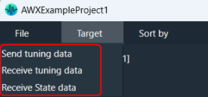
You must connect the device instance containing the tuning data to the physical/virtual device to send tuning data to the physical device.

Connect Device

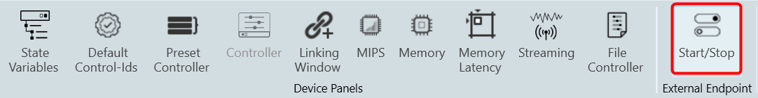
Use the Connect Device option to connect to a device.

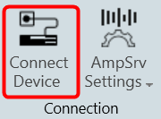
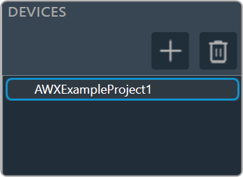
To connect a device, select the device from the device list, and then click Connect Device.

If there is no instance of AmpSrv2 running with the required port, then a new instance of AmpSrv2 will start. Otherwise, it will use the current AmpSrv2 instance.

The communication port between GTT and AmpSrv2 is calculated automatically on the GTT side: 24575 + HiQnet node address of the device instance.

If AmpSrv2 is started by GTT, then AmpSrv2 settings will not be stored.

If AmpSrv2 settings change permanently, then a manual start of AmpSrv2 is required.

The automatic startup of AmpSrv2 only works for single-device instances. If you want to connect to multiple device instances in parallel, you will need to manually start multiple AmpSrv2 instances (running on the requested port addresses).

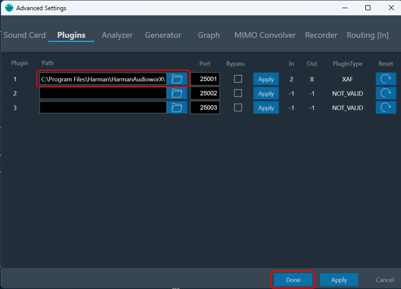
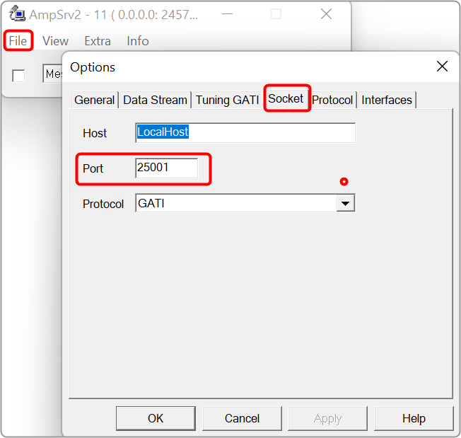
From Herbie Hancock release onward, the default port of the virtual device has changed. The default port is now 25001 (before it was 8080).
If an old audio library is used, the settings should be adapted manually. In AmpSrv2 > File > Options > click Socket.
Graphical user interface, application Description automatically generated

Disconnect Device: Click the Disconnect Device button in the ribbon bar.

If AmpSrv2 was launched by GTT, AmpSrv2 will be closed. Otherwise, AmpSrv2 will keep on running.

AmpSrv2 Settings

AmpSrv2 is software to connect the tuning tool to either a physical target device or a virtual amplifier.

The AmpSrv2 shows the following menus:

  • File: Click on the File menu to open the Options window or close the AmpSrv2.
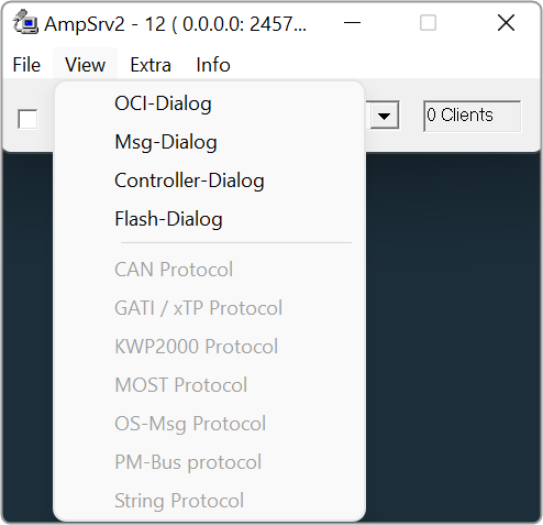
  • View: Click on the View menu to open dialogues and protocols functionalities.
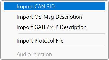
  • Extra: Click on the Extra menu to import CAN SID, OS-Msg Description, GATI/xTP Description, and Protocol file.
    Graphical user interface, text, application, chat or text message Description automatically generated
  • Info: To get the AmpSrv2 version and license details.

AmpSrv2 License

The AmpSrv2 dialogues and protocols functionalities are licensed-based. If any dialog or protocol is grayed out or not available, this means you have a limited license.

The AmpSrv2 is shipped with a limited license (Customer.lic).

Graphical user interface, application Description automatically generated

To check AmpSrv2 license:

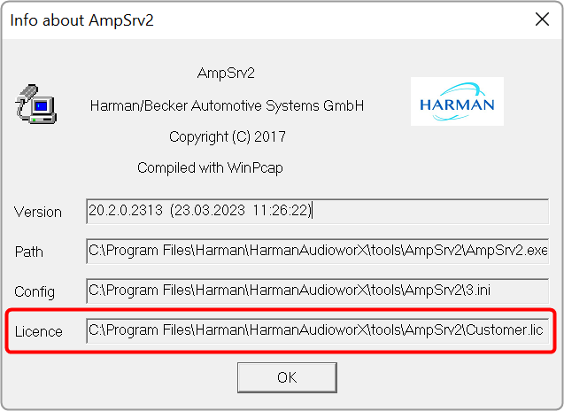
  1. On the AmpSrv2 window, click Info, and then click About. This displays the AmpSrv2 info screen. Verify the license information.
    Graphical user interface, application Description automatically generated

To activate the new AmpSrv2 license:

  1. Navigate to the C:Program FilesHarmanHarmanAudioworXtoolsAmpSrv2.
  2. Locate the Customer.lic file (license file) and delete the existing license file.
  3. Copy and paste the new license file (xxx.lic) into the same AmpSrv2 directory.

To changing AmpSrv2 Settings:

  1. On the AmpSrv2 window, click File, and then click the option. This opens the Options window.
  2. On the Socket tab, set the protocol to GATI.
    Graphical user interface, application Description automatically generated

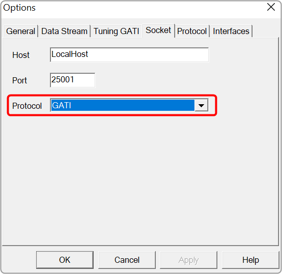
If you experience network conflicts, choose a different port above 50000 because port 8080 is very popular. Your selection must appear in the VST client (probably AudioMulch).

  1. On the Tuning GATI tab, set the Databytes per to 192, and click Ok.
  2. On the AmpSrv2 window, check the checkbox.
    Graphical user interface, application Description automatically generated

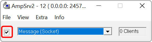
When you start GTT and connect to AmpSrv2, the AmpSrv2 window will show the number of connected clients.

Once you have completed the necessary Ampsrv2 modifications, go to AmpSrv2 Settings and save the Ampsrv2 modifications.

This saved configuration will now be used for this specific device on Connect Device. The saved configuration will also be exported/imported using the GTT project Export/Import functionality.

If no AmpSrv2 settings are connected with the device, the default settings will be used. You can modify the GTT default AmpSrv2 settings. Follow the steps mentioned in the above topic “To changing AmpSrv2 Settings”.

The AmpSrv2 window will appear, and the user can modify the settings, which will be considered the Default Settings for GTT.

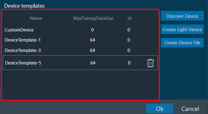
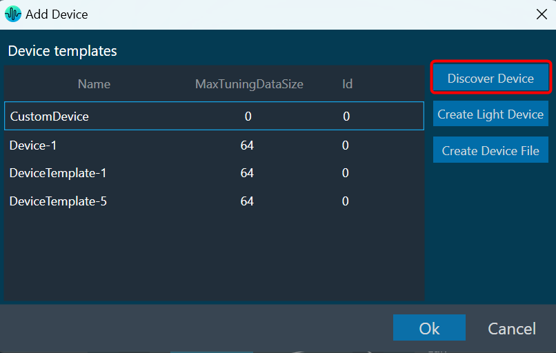
In the case of a Discover device, you should first open AmpSrv2 Settings, modify settings as needed, and then click on Discover Device. This modified configuration will be used to discover the device.

In the AmpSrv2 window, the port number of the server is not saved in the General tab.
Graphical user interface, text, application, email Description automatically generated

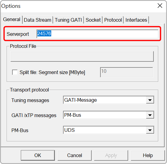
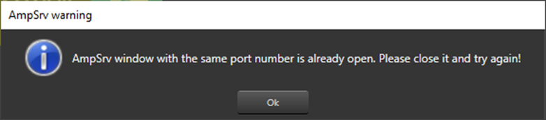
Two AmpSrv2 windows with the same port number cannot be opened or an error message will be displayed.
Graphical user interface Description automatically generated

Device Panels

The Device Panel group offers a set of tools that lets you perform various functions on a device.

The following tools are available on the Device panel.

  • State Variables:  To view the memory layout of each device instance
  • Default Control-Ids: To specify which default control ids should appear in the “Control In” control list.
  • Preset Controller: The preset controller is the central place for managing and organizing how you will load presets in your signal flow.
  • Controller:  To send instance commands.
  • Link Window:  To assist you by reducing the number of audio parameter configurations.
  • MIPS: To view the CPU load of cores, instances, and audio objects of the connected device.
  • Memory:To the CPU memory of cores, instances, and audio objects of the device in a single multi-level grid.
  • Memory Latency: To shows the amount of time taken by the CPU from initiating a request for assessing memory to actual reading or writing data at the requested memory.
  • Streaming: To stream live data from the device.
  • File Controller:  To send audio files from GTT to device.

Streaming

You can stream live data from the device. The state variables which support streaming and polling are displayed in the state variable explorer tree with “Category” other than “Tuning”.
The streaming and polling are used to monitor the signal flow of different parameters in a Signal Flow Designer.

Streaming can be beneficial when you need to constantly monitor a signal for a specific channel. If any changes are made to the signal flow design, the updated values will automatically be displayed through streaming. However, for non-streamable parameters, GTT will transmit a single command and receive the corresponding value from the device in response.

To access this feature, you will need a license for unlocking. Kindly contact the license administrator to obtain the necessary license.

The object tree displays filtered state variables that support streaming and polling.

Streaming state variables are highlighted in white, while polling state variables are highlighted in orange.

The default display of state variables in the object tree is set to show “after calculation” data for streaming out. However, if you want to display “before calculation” state variables, select the “Display IN Channels” option. The IN state variables indicated with a blue color and OUT state variables indicated with a red color, with keywords denoting their specified type.

Below table describes the audio objects that support streaming.

Audio Object Parameter Name State Variable Streamable
Level Monitor Level_Value Yes True
Compressor Attenuation Yes True
VNC Control VNCControlStates Yes True
NoiseESt StreamingParam Yes True
AlaControl AlaControlStates Yes True
FFTCalc FFTCalcState Yes True
Ducker State params Yes True
dbXLimiter States Yes True
AudioToControl AudioToControlState Yes True
Limiter Attenuation Yes True

Configure Streaming

If you want to stream streamable state variable, then you can enable Streaming option.

To enable Streaming per core:

  1. Open the Device View and select the Virtual core layer of the device.
  2. Go the Virtual core properties, select the Streaming checkbox, and set a number of State Variables per core.

Maximum 32 state variables can be configured for streaming.

If you want to perform the operation using non-streamable state variables, then there is no need to enable these options

Memory Latency

Memory latency shows the amount of time taken by the CPU from initiating a request for assessing memory to actual reading or writing data at the requested memory.

In AudioworX, the latency of the memory request is abstracted and only measured in relative levels.

  • Level 1 – fastest memory available in the platform.
  • Level 16 – slowest.

The Memory Latency Editor provides a way to configure latency levels for individual audio object memory records from GTT.

During design time, GTT retrieves memory records for audio objects from the audio library in the following cases:

  • While adding an audio object.
  • Modifying audio object i.e changing the number of inputs, outputs, number of elements, or selected mode.
  • Modifying additional parameter value.
  • Upgrading audio object.
  • Import of project which defaults to a different dll other than the created one.
  • Upgrading device framework to version 17 dll or above.
  • The changing target type of Core.
  • Changing Sample Rate or Block Length of instance.

GTT supports Memory Latency feature only if the xAF dll version is 17.x.x.xxx or above.

Editing Memory Latency

Memory records will have default latency selected by the Audio Object developer. GTT provides the option to set the latency for every memory record of the audio object in the Memory Latency Editor.

  1. Select the device node and click Memory Latency. This opens the Memory Latency window for the selected device. When the Memory window is launched, a multi-level collapsible grid with core, instance, and audio objects will be displayed.

1 – Header, 2 – Column Filter, 3 – Header, 4 – Latency Sector

  • Multiple memory latency record selection: You can select multiple records in the memory latency window.
    • To select the specific rows – Hold Ctrl and click on the required rows. This method is useful when you want to preform action on specifics rows.
    • To select a set of rows – Click on the first row of the set, hold Shift, and then select last row of the set. This method is most useful when selecting a large number of rows in a range.

Sum of all the selected memory latency record size will be shown as “Total size of the selected records in bytes” in the memory latency window.

“Total size of the selected records in bytes” will be visible only on selecting any memory latency record in the window.

  • Reset to default latency level: You can reset the selected records to its default latency level.  Right click on selected records or anywhere on latency grid. A context menu “Reset to default” option will be displayed. Click on the “Reset to default” option, all the selected records of the latency level will be set to default value which is “LEVEL5”. Click on “Save” button and it will be saved into database.
    • To reset records to default latency level for the specific rows – Hold Ctrl, select on the required rows, and then right-click on selected records. A context menu “Reset to default” option will be displayed. Click on the “Reset to default” option.
    • To reset records to default latency level for a set of row – Click on the first row of the set, hold Shift, select last row of the set, and then right-click on selected records. A context menu “Reset to default” option will be displayed. Click on the “Reset to default” option.
  • Saving Latency memory: Only Latency can be selected. Other attributes of memory records are read-only. When you click on Save, the Latency for the memory record will be saved.

The Save Button is disabled until a change in latency is detected.

  • Send Memory Records to Device: Send Signal Flow will handle sending Memory records to the Device with a specified latency. When the signal flow send is successful, the device will boot up with the memory latency specified.
  • Import Export of Project having Memory Record: Memory latency is preserved if the export and import occur on the same xAF dll by version.
    If the dll version changes, Import will generate a new memory record based on the new target xAF dll version.
  • Copy Paste of Audio Object or Core Object Containing Memory Latency: If the properties of the source and targets are the same, memory latency is retained in the pasted object.
  • CSV Import/Export: You can export and import of memory map to CSV files. The primary operation of this feature is to export memory latency to CSV, adjust memory levels, and then import the updated memory levels back into the GTT. When the memory map form file does not match the one in GTT, GTT will request permission to import only the items that match.

Memory

The Memory window presents the CPU memory of cores, core objects and audio objects of the device in a single multi-level grid.

Memory profiling data of cores and core object is fetched from the device (hardware) using xTP Commands, and the memory of the audio object is fetched based on its memory latency configurations.

Overhead Memory consumed by core and instance is calculated and displayed as ‘Framework Memory’. You can optimize signal flow or adjust latency based on this information.

Apart from memory profiling data, the class size of each audio object is also fetched from the device using xTP commands and displayed in the memory window from the X release(24.x.x.xxxx) audio library onwards.

Memory window is only enabled if the device xAF dll version is 18.x.x.xxx or higher.

Before starting the Memory window, the signal flow should be flashed.

If the memory latency configuration is updated, the signal flow should be flashed again and the memory window should be restarted.

Memory profiling data of non-xAF instance core objects (Buffer,Splitter…etc) is available only from the X release(24.x.x.xxxx) audio library onwards.

Launch Memory Profiling

Steps to launch Memory profiling:

  1. Select the device node and click Memory. This opens the Memory window for the selected device.

When the Memory window opens, it will show a collapsible grid with core, instance, and audio objects.

  • The physical core memory values displayed are the sum of its virtual cores.
  • xTP Commands retrieve virtual core and core object memory from the device.
  • Memory latency configurations are used to fetch audio-object memory.
  • Overhead Memory consumed by the core and instance is calculated and displayed as ‘Framework Memory’.
  • xTP Commands are used to retrieve audio object class size based on the block ID of the audio object.

  • Expand All: Expands all rows of the collapsible grid.
  • Collapse All: Collapses all rows of the collapsible grid.
  • Export to CSV: Click on the Export option to export the memory data of the device in a CSV file.  The exported file will have a row for Framework Memory for Virtual core, Instance, Audio Objects, and Physical core along with columns PhysicalCoreName, VirtualCoreName, CoreObjectName, ObjectType, ObjectName, BlockId, AO Class Size and Level1 to Level 16 as per the below image.