Real Time Data View

The ribbon bar provides a quick view of real-time measurements for RMS, THD, True Peak, Peak-Frequency, and THD+N. By default, the tool selects two channels for this display, and you can view the live data of two channels simultaneously. If you want to monitor a different channel, you can easily select it from the options available on the ribbon bar.

When using a average mode, it will load average channels by default; otherwise, it will pick the first channels that are listed on the analyzer.

RMS Values will provide the selected weighting indication (A B C D).

The Weighting is displayed on the ribbon bar when configured in Advanced Settings. Go to Advanced Settings > Analyzer > Freq Weight RMS to activate weighting.

There are five live data columns available for selection:

  • RMS
  • THD
  • True Peak
  • Peak-Frequency
  • THD+N
  • Delay

For example, for the 1 kHz sine wave, the live ribbon with peak trace enabled and graph will look as follows:

CPU Load

In the RTA graph view, the CPU load provided by Audio Engine is displayed in percentage (up to 2 decimals). This will be shown in different colors based on the level as below.

  • Normal: 0-70 (Green color)
  • Medium: 71-95 (Yellow color)
  • High: Greater than 96 (Red color)

Rate Control

The Rate Control audio object controls the rate at which control signals can pass through the object. This is implemented by blocking the controls for a duration that is specified as a tuning parameter.

Rate control Properties

Below table describes the audio object properties and functionalities.

Properties Description
Number of controls Enter the number of control inputs.

The number of control outputs is always 2. The index of the pin (which receives the first control signal) is sent out on the left output pin first and then the control signal itself is sent on the right output pin.

  • Range: 1 to 255
  • Data type: xFloat32
  • Default: 1
Display Name Display name of the Rate control audio object in signal flow design. It can be changed based on the intended usage of the object.

Mode

There are currently no modes available for the Rate control audio object.

Additional parameters

There are no additional parameters available for the Rate control audio object.

Tuning Parameters

There are blocking times associated with each control input pin which could be changed as a tuning parameter.

Parameter Description Data Type Range Default Unit
BlockingTime Time for which any new control signal is blocked xFloat32 0 – 60 0 seconds

Control Interface

The object supports configurable number of control inputs ranging from 1 to 255. The default number of control input is 1. The objects supports two control outputs.

Native Panel

Rate control audio object does not support a native panel.

Overview

This guide explores a comprehensive library of audio algorithms from Harman. It includes over 90 algorithms that can be used to create new, flexible audio processing units (Compound Audio Objects). These CAOs can be fine-tuned, protected with passwords, and shared as easily as any individual audio object.

The audio objects are categorized into the following groups in the GTT.

Control Generator

The Control Generator audio object allows to generate a constant control value at a specified time.

Control Generator Properties

Below table describes the audio object properties and functionalities.

Properties Description
# of  Control outputs Enter the number of control outputs.
In Single control mode, the number of control outputs is configurable between 1 to 255.
In Multi control mode, the number of control outputs is the same as the number of control inputs.

  • Range: 1 to 255 (Min – 1 and Max – 255)
  • By default, the number of output channels is set to 1.
Display Name Display the name of the Control Generator audio object in signal flow design. It can be changed based on the intended usage of the object.
Object Mode This audio object can be configured in two operation modes.

  • Single control
  • Multi control

Mode

The object operates in one of the following two modes:

Mode Description
Single control In this mode, the object has a single control input and configurable control outputs ranging from 1 to 255.
It has a single set of tuning parameters that decide the functioning of all control outputs. Based on the Control value and Trigger time configured, which is applied to all the control outputs,  the constant control value is sent out every “n” seconds i.e. trigger time configured.
If its value is 0 the control value is sent out just once.

This is the default mode.

Multi control This audio object can be configured with control channels ranging from 1 to 255.
The number of control inputs will be equal to the control outputs. The object has a separate set of tuning parameters that decide the functioning of each control output. Control value and Trigger time can be configured separately for each control output.
The default number of control channels shall be 1.

The control input in both modes is triggered only and the value at the control output is set by the Control value tuning parameter.

Additional parameters

There are no additional parameters available for the Control Generator audio object.

Tuning Parameters

The following are the paraments that can be tuned from GTT.

Parameter Description Data Type Range Default Unit
Control Value The value which is sent out to the control output. Setting this value will send the constant control value out. xFloat32 Min: single precision float minimum -3.402823 x 10^38

Max: single precision float maximum 3.402823  x 10^38

0.0f NA
Trigger time It is the rate at which the control value is sent on the control output.

Setting this tuning parameter shall send the constant control value out. If its value is 0 the control value is sent out just once. If its value is greater than 0, let’s say a value of N, the control value shall be sent out every N seconds.

xFloat32 0 – 600 0.0f seconds

Control Interface

The Single-control mode has a single control input and configurable control outputs. The control outputs are configured using the “# of Control outputs” property.  The control output value ranges from 1 to 255.

By default, control input and control output is 1.

The Multi-control mode has configurable control outputs. The control outputs are configured using the “# of Control outputs” property.  The control output value ranges from 1 to 255.
The number of control inputs is equal to the control outputs.

Native Panel

The Control Generator audio object does not support a native panel.

Lookup Table (LUT) Panel

The LUT object supports native panel.  Double-click on the LUT object to open the native panel and set the values accordingly.

  • Redo/Undo: The redo and undo functions enable you to rollback or repeat the modifications made to panel cell values, units, minimums, and maximums.
  • Customizable Axis Label: The customizable axis label allows you to change the axis label name. Double-clicking on the axis label will show a textbox where you can change the axis label name.
  • Offset: An offset value is a number added or subtracted from selected cells.
  • Export: Using the export option, you can export the currently opened LUT tab data into .csv format.

Only tuning data will be exported. Unit Type, Min, and Max values will not be part of the export.

  • Import: You can import LUT data into the application using a .csv file. This feature allows you to reuse exported files or import externally computed data.
    The file must follow the validation rules below before import.

    • The file must be in .csv format.
    • The file must contain the same number of rows and columns as the currently opened LUT tab.
    • The first column must represent the Axis, and its values should be in ascending order.
    • All cell values in the file must be within the defined unit’s minimum and maximum limits. Once the import is successful, the Undo button will be enabled, allowing you to revert the import operation if necessary.

Fader Matrix

The FaderMatrix audio object is used to calculate the weighted output based on a combination of input audio where the weighting factors are provided as control input.

Use Case: The FaderMatrix takes in a configurable number of input, output and control channels. Each output of this object is a weighted sum of all the input channels where weighting factors can be tuned from control inputs.

Fader Matrix Properties

Below table describes about the FaderMatrix audio object properties and functionality.

Properties Description
# of Audio In Number of input channels.

  • Range: 1 to 64
  • Default: 2
# of Audio Out Number of output channels.

  • Range: 1 to 64
  • Default: 2
# of Elements Number of Control Inputs.

  • Range: 0 to 64
  • Default: 0
Display Name Display the name of the FaderMatrix audio object in signal flow design. It can be changed based on the intended usage of the object.

Mode

There are no modes available for FaderMatrix audio object.

Additional Parameters

The FaderMatrix audio object can be configured with the following additional parameter:

Parameters Description
Gain Type The audio object has an additional configuration ‘Gain Type’ to specify the weighting factors scale.

  • 0 – Linear [default]: Weights are configurable in a linear scale in the range of -100 to 100.
  • 1 – Logarithmic: Weights are configurable in a logarithmic scale in the range between -128 to 40 dB.

Tuning Parameters

The FaderMatrix audio object has one control index tuning parameter for each input channel that will used to compute the output of each channel. Thus, there will be NumInputs * NumOutputs control indices (tuning parameters).

When the control index is set to zero, none of the control inputs will be used and this particular input will not be considered for computation of that particular output

Parameter Description Range Unit
Control Index Index of the control input for selecting weight factor for each input and output combination. 0 to NumElements None

Control Interface

The FaderMatrix control is triggered whenever a control message is addressed to the audio object. The FaderMatrix audio object has configurable control input pins for weighting factors.

Parameter Description Gain Type Data Type Range Default Unit
Weighting Factor Weight factor for each input and output combination. Linear Float -100 to 100 0 None
Logarithmic Float -128 to 40 -128 dB

Native Panel

The Fader Matrix AO supports native panel called Fader Matrix Panel. The rows and columns of Fader Matrix panel is determined by the number of Audio inputs and Audio outputs configured. For more details, refer to the Fader Matrix Panel.

VolumeLite

The purpose of the VolumeLite audio object is to control the volume in the audio pipeline. The VolumeLite audio object is lightweight and different from the “Volume Mute” AO. The object can alter the output volume by either attenuating or amplifying the audio.
This audio object supports ramping and each channel has its own set of – state variables as well as ramping parameters.

Use Case: The object can be used to control the volume of an audio channel.

VolumeLite Properties

Below table describes the VolumeLite audio object properties and functionality.

Properties Description
# of Channels In SFD, the number of channels is specified, and the number of input channels is equal to the number of output channels.

  • Range: 1 to 128
  • Default: 1
Block Control The object supports Block Control when the object is configured with more than one channel. It has one block control input which controls the output volume of which size is equal to the number of channels configured for the audio object. Block Control is enabled by default and cannot be disabled.
Object Mode There are no mode available for VolumeLite audio objects.
Additional Parameters VolumeLite object has one additional parameters — Boot Level

Additional Parameters

Parameter Description
Boot Level It specifies the required volume level at boot time when configured. It is applicable for all the channels.

Range: -128 dB to +20 dB.

Default: 0 dB

Tuning Parameters

The following are the tuning parameters that can be configured from GTT.

Parameters Description Range Default Data Type
Ramp Up Time Ramp up time in ms per channel. 0 to 1000 ms 5 ms Float
Ramp Down Time Ramp downtime in ms per channel. 0 to 1000 ms 5 ms Float
Ramp Shape The shape of the volume will change accordingly once it is triggered and applied across all channels.
  • Linear
  • Exponential
Linear ULong
Volume Volume to be applied per input channel -128 to 20 dB 0 dB Float

All the channels can be tuned with one command as all are in the same subblock compared to the Volume Mute object.

Control Interface

The Volume control is triggered whenever a control message is addressed to the audio object. Block Control is deployed only when the object has more than one channel. It has one block control input, the size of which is equal to the number of channels configured for the audio object.

Parameters Description Range Unit
Volume Volume to be applied per input channel -128 to 20 dB dB

Native Panel

The native panel for the VolumeLite audio object is under development.

Control Mixer panel

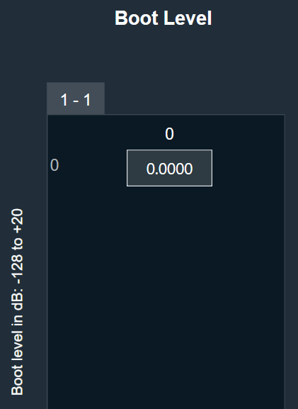
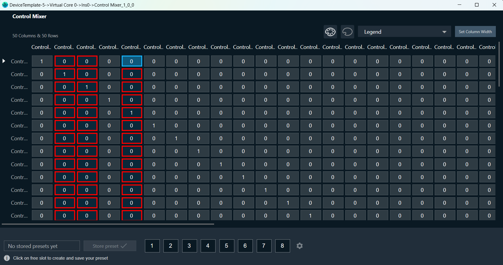
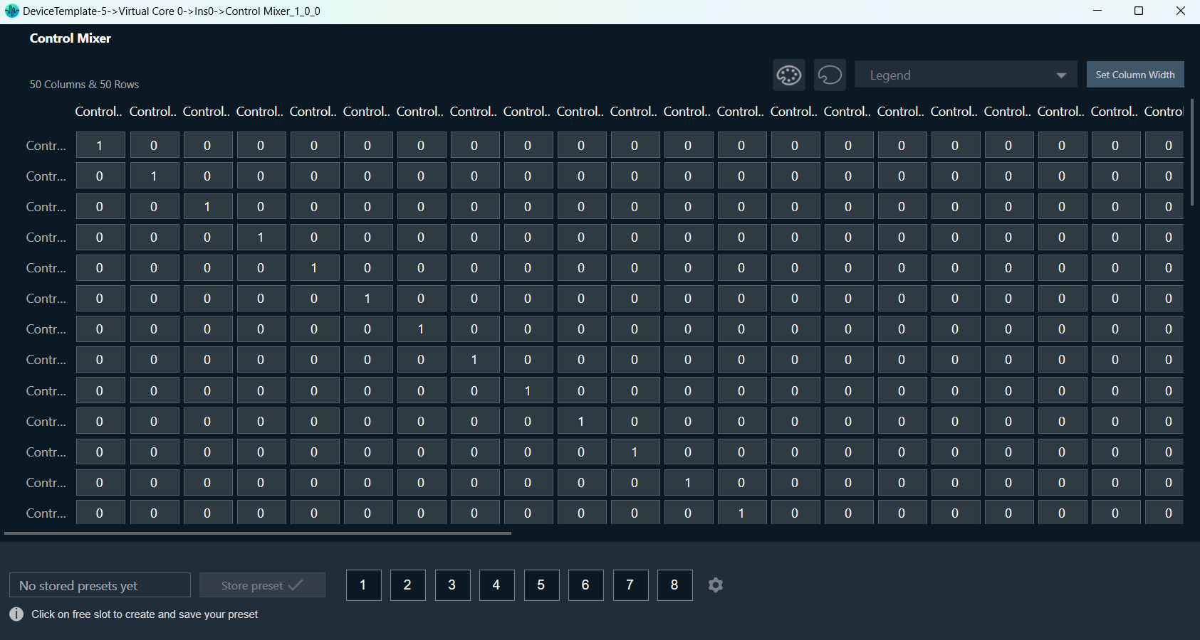
The Control Mixer object supports a native panel. The native panel window consists of rows and columns, the number of which depends on the “number of control inputs and outputs” configured.

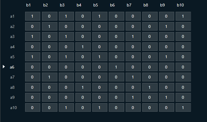
In Non-Weight Mode, table cells can have only two values 0 or 1.

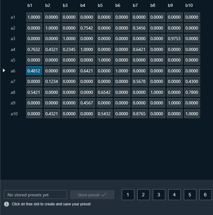
In Weight Mode, table cells can have values from 0 to 1.

Control Mixer supports copy-pasting values from and into Excel sheets.

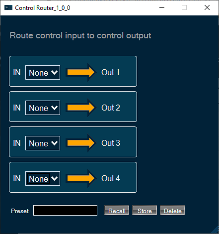
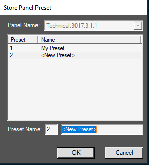
You can store and recall the specific configuration via the Store Preset option available on the panel. Configure the tuning parameters, select the free preset slot numbers, enter the slot’s name, and click Store preset. This saves and stores the current tuning data for the selected slot.

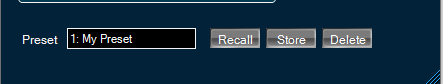
If you do not enter a name of the slot, then it will take the default named “New Preset”.

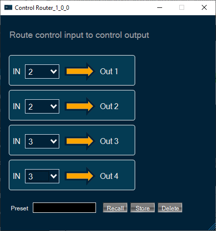
You can switch between preset slots and apply their values by simply clicking on them. Additionally, after clicking to override the preset, you can modify the tuning values in that tab or change the preset name.

To reset the selected preset or all the preset values.

  • Click Reset Selected to clear the preset that is currently selected.
  • Click Reset All to clear every preset in the corresponding native panel.

Coloring Feature

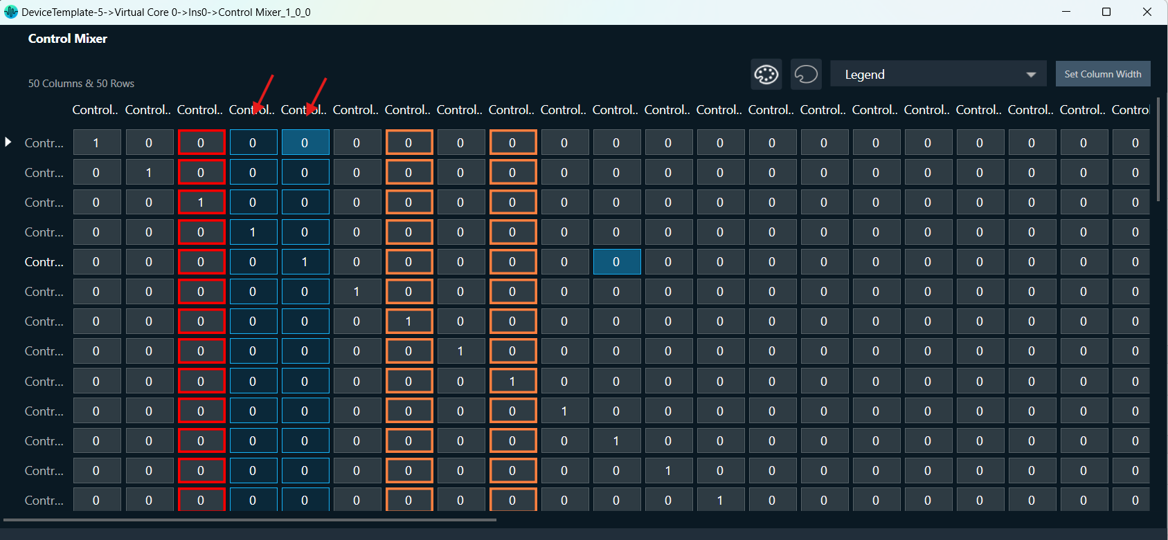
The Control Mixer Panel supports organizing input or output groups by providing color to the selected rows or columns, respectively. Coloring can be provided either row-wise or column-wise, not both together.

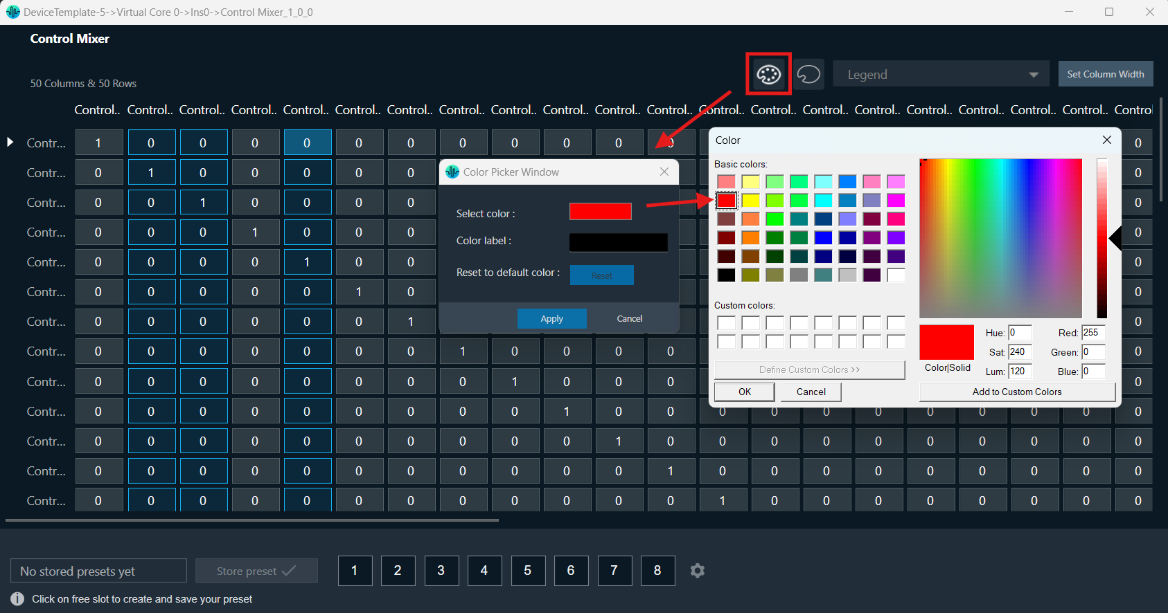
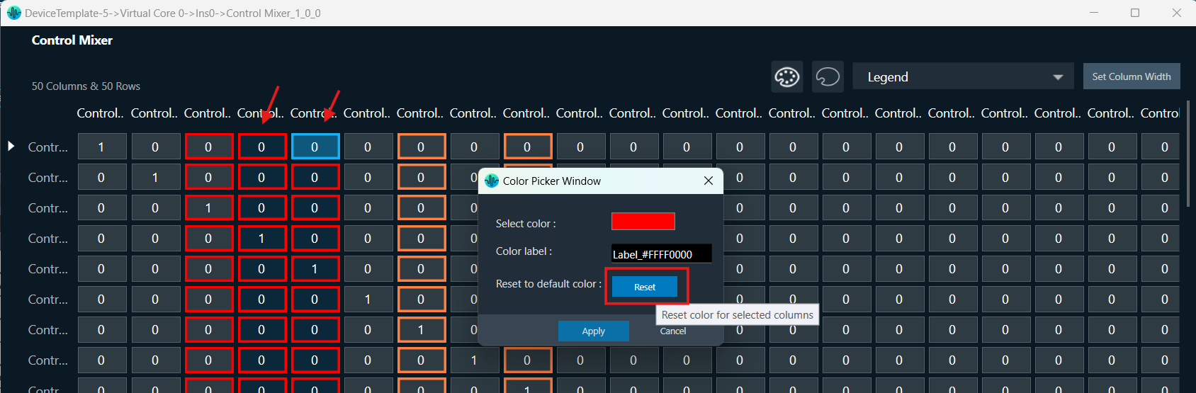
Apply Color: You can select rows or columns and click on the color pallet icon on the top right side of the Control Mixer panel. A Color Picker window will appear, providing options to select color, label color, and apply color.
The color pallet icon is enabled only on row or column selection. On click of Apply button of the Color Picker Window, the chosen color is applied to the cell borders of selected rows or columns.
Providing a label to the chosen color is optional; if no label is provided, then a default label is added in the format ‘Label_Color’ (where ‘Color’ indicates the hex value of selected color).

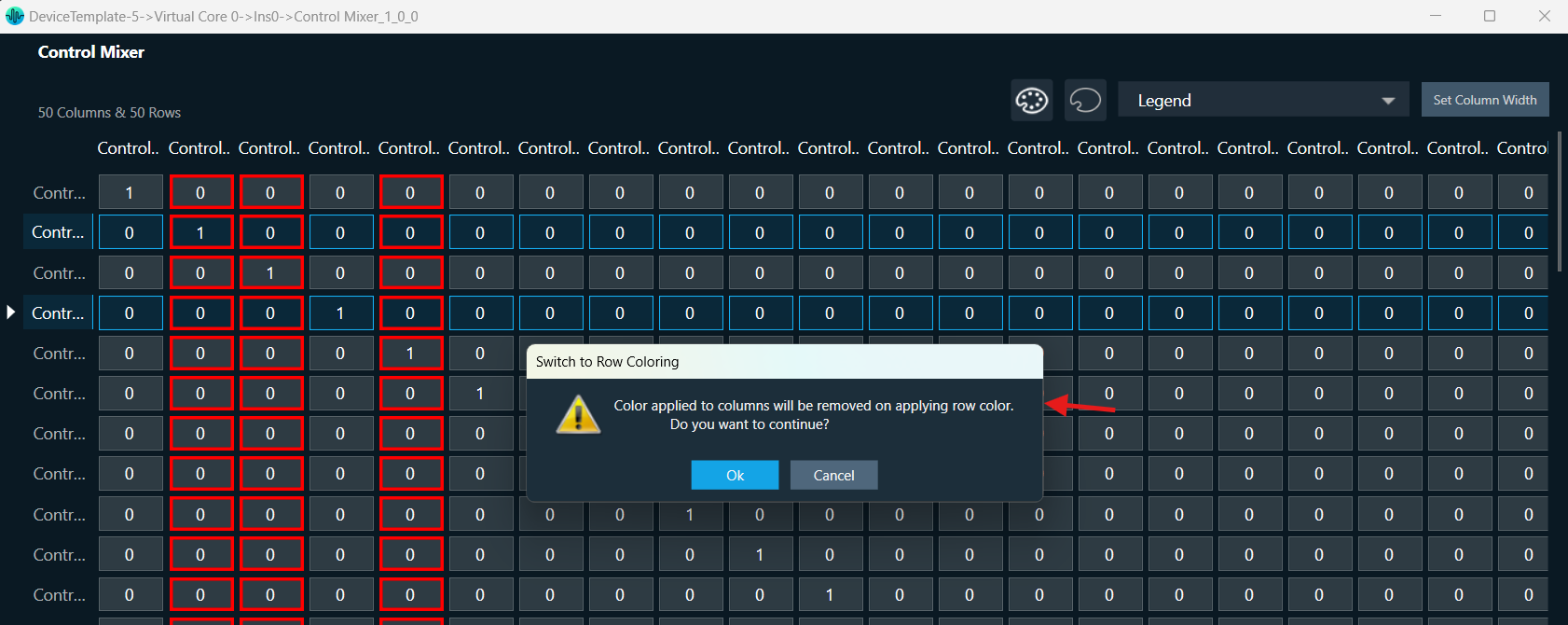
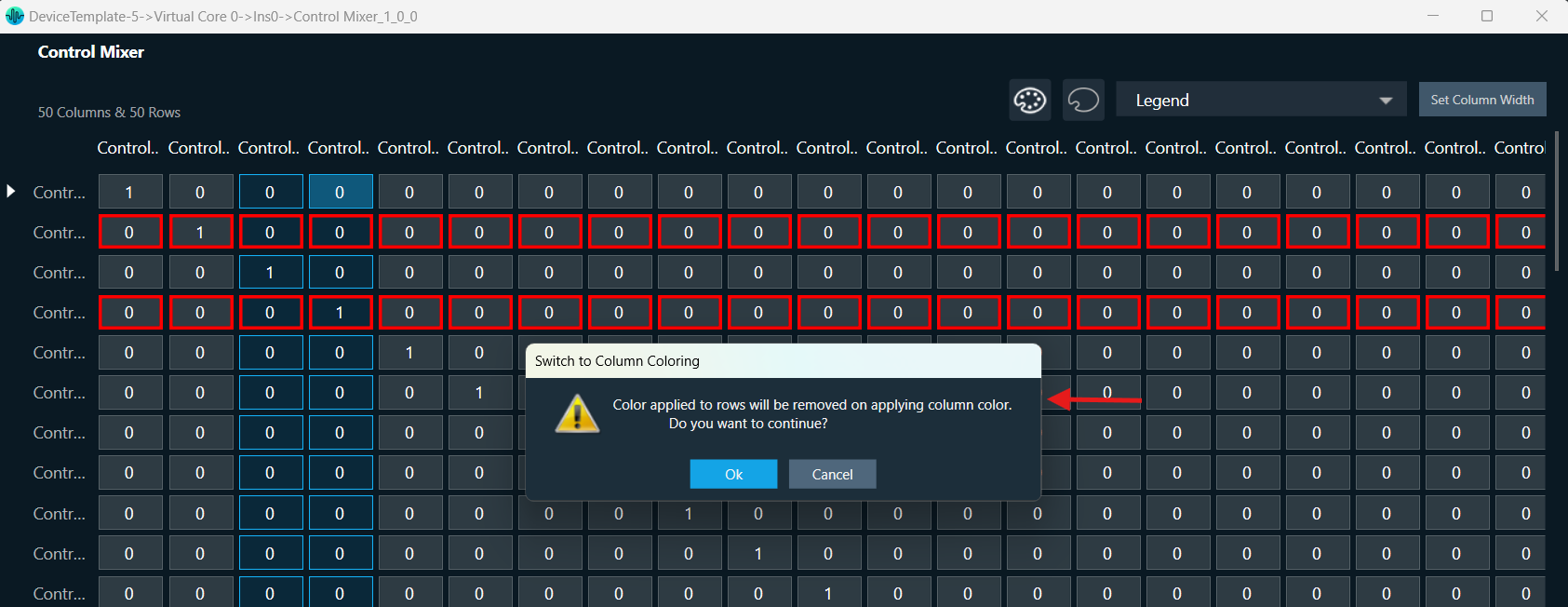
Row-wise or column-wise switching: If colors have already been applied to one or more columns, and you attempt to select rows to color, a confirmation message will appear. This message will inform you that choosing to color the rows will reset any colors applied to the columns. If you confirm this action, you can proceed with coloring the rows.
The same process works in reverse; if you have already set the colors for the rows and then attempt to select colors for the columns, a confirmation message will pop up. This message will inform you that applying column colors will reset the previously applied row colors. Once you confirm, you can continue with coloring the columns.

If both a column and a row are selected, when you apply a color, the last selection determines the application. If the row is selected last, the color applies to the row; if the column is selected last, it applies to the column.

Reset selected rows or columns:  The Color Picker window has a Reset button that allows you to restore selected rows or columns to their default color. The Reset button is activated only when color has been applied to the selected rows or columns.

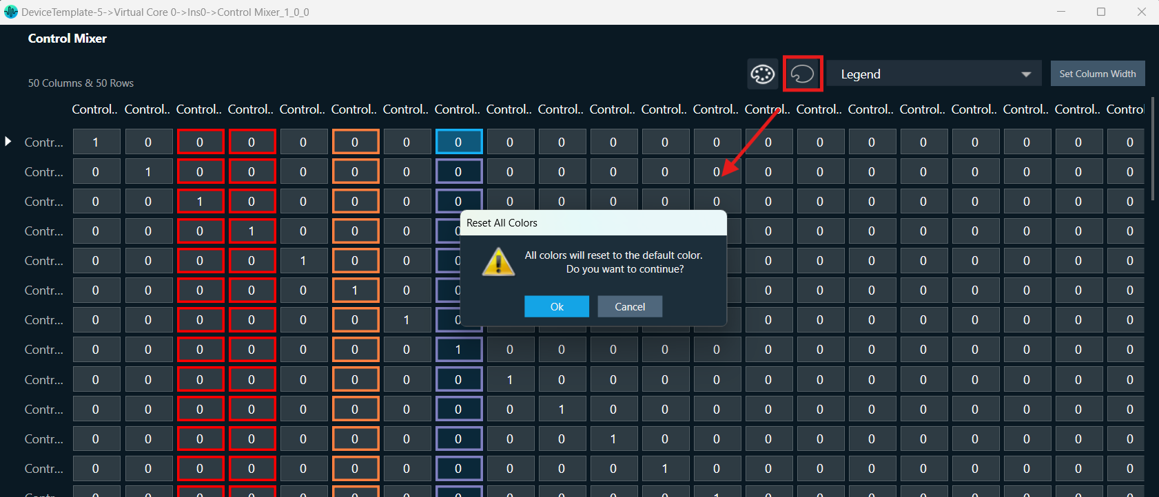
Reset All Colors: You can click on the empty color pallet icon on top right side of Control Mixer panel to reset all colors applied to the panel.

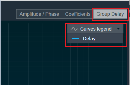
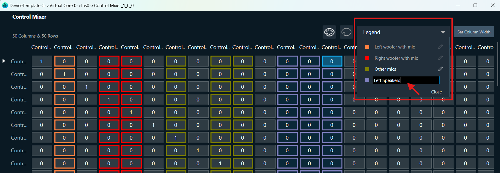
Legend: You can click on the Legend dropdown on the top right side of ControlMixer panel to view the color applied and associated labels. The labels can be edited from the legends dropdown by clicking on the edit button on the right.

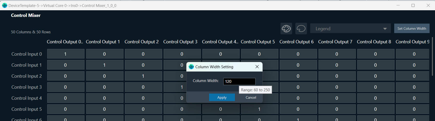
Column Width Setting

You can set the column width of the Control Mixer panel by clicking on the ‘Set Column Width’ button at the top right corner. When you click this button, a window will open that allows you to set the width for all columns in the panel. The permitted width range is between 60 and 250. Any column width set using this option will be saved and will persist even after the panel is relaunched.

You can adjust the column width by dragging the right border.  Any width changes made by dragging the column border will not be saved when the panel is relaunched.

Control Router panel

The Control Router audio object supports native panel. The native panel window is a dynamic native panel. Panel get adapted in size based on the Router AO configuration.

By default, all outputs are disconnected.

Every output has an input that can be configured. More than one output can be assigned to a single input signal.
It is possible that some input signals are not assigned to any output.

Additionally, this panel enables to store presets for specific configuration.

Name of preset is configurable in separate window after click Store button:

FastConv Panel

Fast Conv filter native panel allows you to configure the Mode of each enabled filter and to load coefficients as well. In order to see the graphs, you need to import coefficients. Use ‘Import’ or ‘Import All’ option to import coefficients.
To open the native panel, double-click on the Fast Conv filter audio object in the signal flow designer.

Amplitude/Phase: When the coefficients are given and “Amplitude/Phase” option is selected, the graph display the value.

Coefficients:  When the coefficients are given and the “Coefficients” option is selected, the graph displays the values as per below figure. You can change the graph style using the “Chart Style” option.

Line chart style: when “Chart Style” selected as Line, the Coefficients graph.
Dot chart style: when “Chart Style” selected as Dot, the Coefficients graph.

Group Delay: When the coefficients are given and “Group Delay” option is selected, the graph display the values.

Curves Legend: This option allows you to show the details of which graph tab (Amplitude/Phase, Coefficients, Group Delay) is selected.

On the selection of Amplitude/Phase graph tab Curves Legend will show below information. A screenshot of a computer Description automatically generated
On the selection of Coefficients graph tab and Chart Styles ‘Dots’, Curves Legend will show below information. A screenshot of a computer Description automatically generated
On the selection of Coefficients graph tab and Chart Styles ‘Line’, Curves Legend will show information. A screenshot of a graph Description automatically generated
On the selection of Group Delay graph tab, Curves Legend will show information. A screenshot of a computer program Description automatically generated

Additional Functionalities

  • Flat: This is used to make the graph flat by making coefficients to 0.
  • Import: This function is used to import the coefficients for a single active filter. Click the “Import” button, then enter the file path and click Ok.
    All coefficients for the selected filter will be imported, as shown in the graph. If the number of coefficients does not match the number of taps as shown in the screenshot below, a warning pop up will appear.
    Click ‘Yes’ to import available coefficients or click ‘No’ to cancel the import.
  • Export: This option is used to export coefficients for selected active filter into csv file.
  • Export All: This option is used to export all active filters in one go. Click the “Export All” button, then enter the path and file name, then click Ok. A xml file will be created which will have coefficients for each active filter.
  • Import All: This option is used to import all coefficients in one go. Click the “Import All” button, then enter the XML file path and click Ok. All the given coefficients will be imported and can be seen in the graph.
  • Read:  This is used to read from the target to display in the panel.
  • Send: This is used to send the values changed in panel to target.