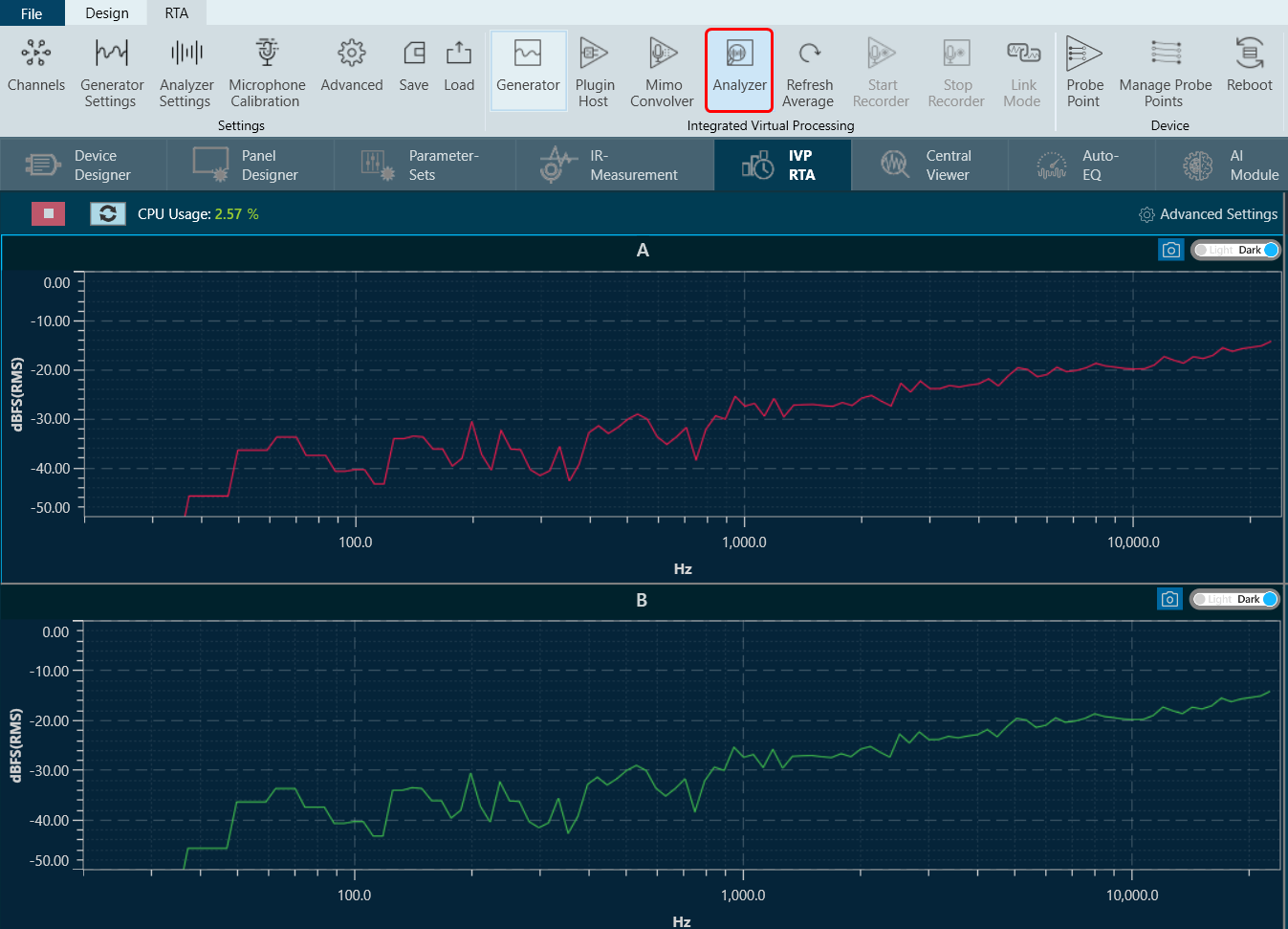
The Real Time Analyzer (RTA) is a multi-channel analyzer for audio signals. It provides time and frequency domain analysis tools to measure RMS or peak levels, frequencies, THD, delays, magnitude, and phase responses. A built-in signal generator provides sine tones, sweeps, and pulses and various noise signals. Using a file player recorded signals can be analyzed.
Related Topics
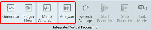
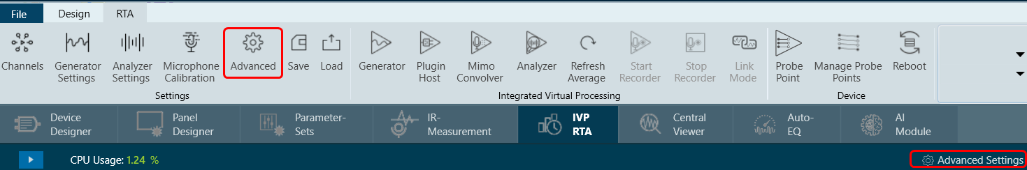
- Real Time Analyzer Components
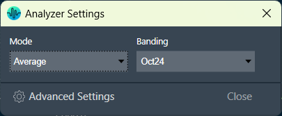
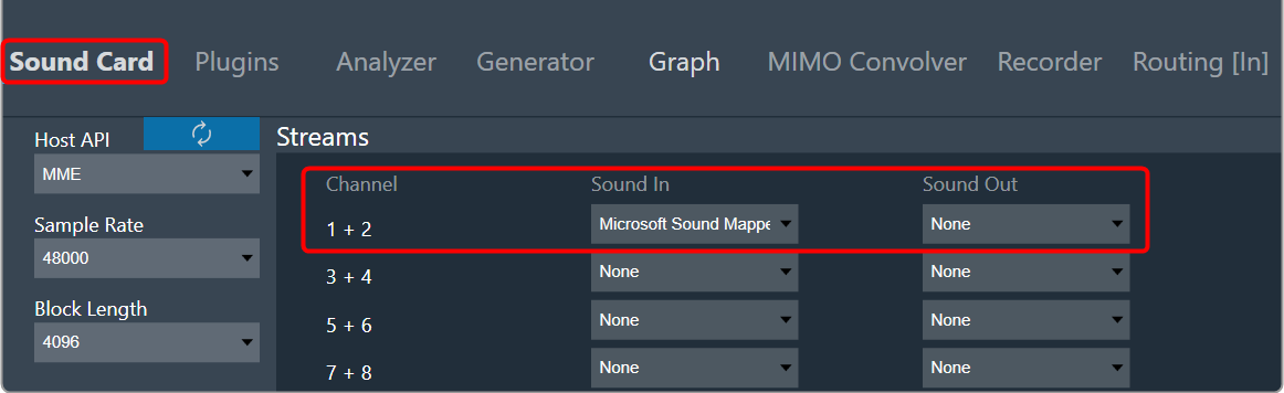
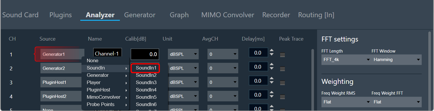
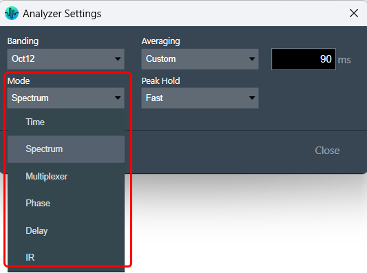
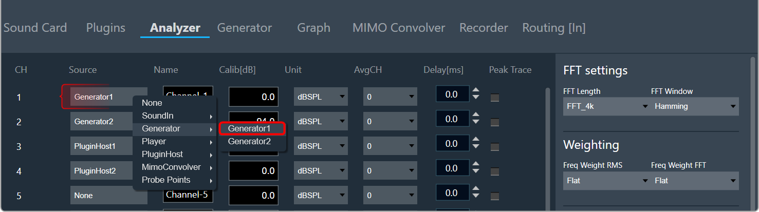
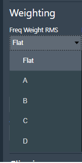
- Real Time Analyzer Settings
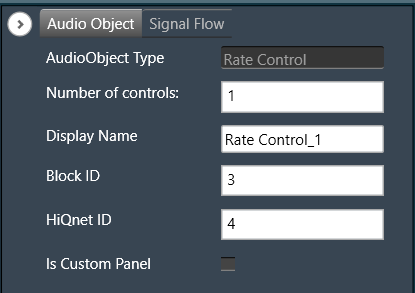
- Probe Point Configuration
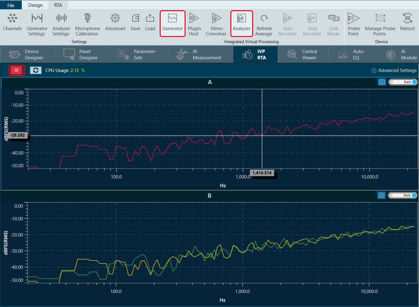
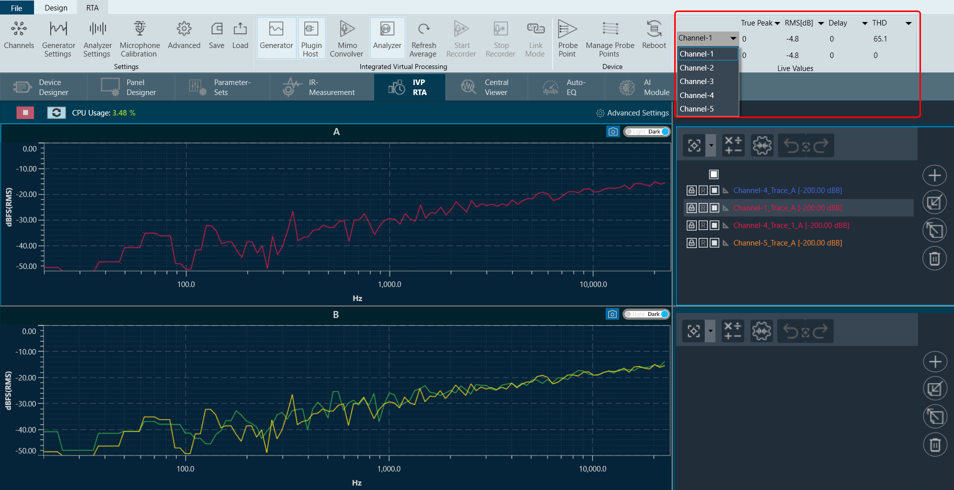
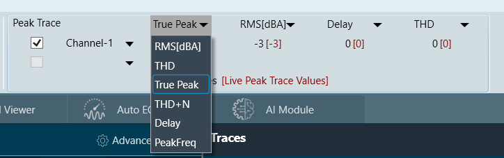
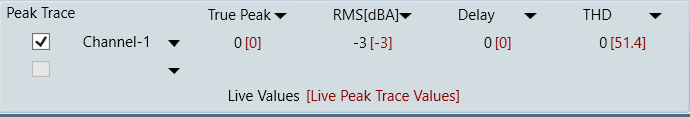
- Real Time Data View
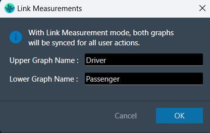
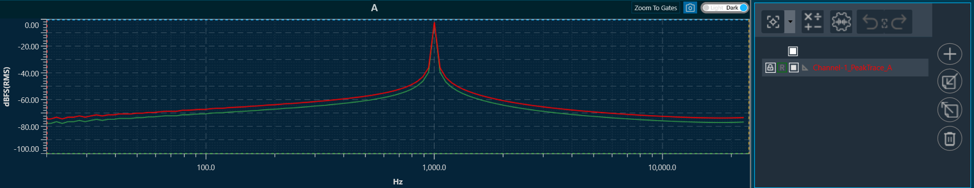
- Graph Settings and Measurement
- Traces
- Analysing Audio Signal
For more details about steps and configuration, you can refer video explaining Step-by-Step Real-Time Analyzer Walkthrough.